ICGOO在线商城 > 光电元件 > 智能,智慧,发光二极管,显示器,图形 > VM800C43A-D

 Datasheet下载
- 型号: VM800C43A-D
- 制造商: FTDI
- 库位|库存: xxxx|xxxx
- 要求:
| 数量阶梯 | 香港交货 | 国内含税 |
| +xxxx | $xxxx | ¥xxxx |
查看当月历史价格
查看今年历史价格
VM800C43A-D产品简介:
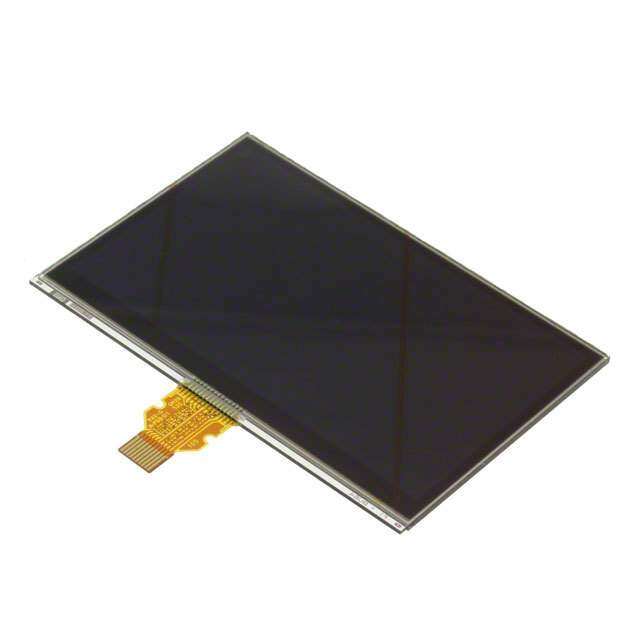
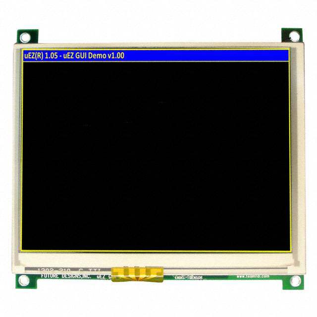
ICGOO电子元器件商城为您提供VM800C43A-D由FTDI设计生产,在icgoo商城现货销售,并且可以通过原厂、代理商等渠道进行代购。 VM800C43A-D价格参考。FTDIVM800C43A-D封装/规格:智能,智慧,发光二极管,显示器,图形, 可传导的 电阻 图形 LCD 显示模块 红色,绿色,蓝色(RGB) TFT - 彩色 SPI 4.3"(109.22mm) 480 x 272。您可以下载VM800C43A-D参考资料、Datasheet数据手册功能说明书,资料中有VM800C43A-D 详细功能的应用电路图电压和使用方法及教程。
Bridgetek Pte Ltd.的VM800C43A-D是一款基于其FT800/FT81x系列嵌入式视频引擎(EVE)芯片的智能图形显示模块。该型号广泛应用于需要高分辨率、低功耗和高效图形处理能力的场景,以下是其主要应用场景:

 1. 智能家居设备
   - 触控面板:用于智能家居控制中心,如温控器、灯光控制器等,提供直观的图形界面和触控操作。
   - 家电显示:集成到智能冰箱、微波炉、咖啡机等家电中,显示状态信息、菜谱或设置选项。

 2. 工业自动化
   - 人机界面(HMI):在工业控制设备中作为触摸屏显示模块,用于监控和控制生产线参数。
   - 仪表盘:用于显示传感器数据、报警信息或其他关键指标。

 3. 消费电子
   - 便携式设备:如手持游戏机、电子书阅读器或健身追踪器,提供高质量的图形显示。
   - 音频设备:用于智能音箱、功放或混音器,显示音乐播放状态、音量调节和均衡器设置。

 4. 医疗设备
   - 健康监测设备:如血压计、血糖仪或心率监测仪,显示测量结果和历史数据。
   - 便携式医疗仪器:为小型医疗设备提供清晰的图形用户界面。

 5. 教育与娱乐
   - 互动教学设备:用于电子白板或学习平板,支持触控和多媒体内容展示。
   - 游戏开发:适用于简单的嵌入式游戏系统,提供流畅的动画和交互体验。

 6. 物联网(IoT)设备
   - 网关设备:作为物联网网关的显示模块,用于配置网络参数或查看设备状态。
   - 环境监测:用于空气质量监测仪、天气站等设备,实时显示数据并支持触控操作。

 7. 车载应用
   - 后视镜显示器:用于倒车摄像头的图像显示。
   - 车内信息娱乐系统:提供导航、音乐播放和车辆状态的图形化界面。

 核心优势
- 低功耗设计:适合电池供电的便携式设备。
- 快速响应:内置硬件加速器,可实现流畅的图形渲染。
- 易用性:支持多种输入方式(触控屏、按键等),简化用户交互。
- 高分辨率:支持高达800x480像素的显示屏,呈现清晰细腻的画面。

综上所述,VM800C43A-D适用于需要高效图形处理和触控功能的各种智能设备,特别适合对成本、功耗和性能有平衡需求的应用场景。
| 参数 | 数值 |
| 产品目录 | |
| 描述 | BOARD EVAL FT800 WITH 4.3 LCD视频 IC 开发工具 Video Module 4.3" Display |
| 产品分类 | |
| 品牌 | FTDI |
| 产品手册 | |
| 产品图片 |
|
| rohs | 符合RoHS无铅 / 符合限制有害物质指令(RoHS)规范要求 |
| 产品系列 | 模拟与数字IC开发工具,视频 IC 开发工具,FTDI VM800C43A-D- |
| 数据手册 | 点击此处下载产品Datasheet点击此处下载产品Datasheet点击此处下载产品Datasheet点击此处下载产品Datasheet |
| 产品型号 | VM800C43A-D |
| 产品 | Development Boards |
| 产品培训模块 | http://www.digikey.se/PTM/IndividualPTM.page?site=se&lang=en&ptm=30292http://www.digikey.cn/PTM/IndividualPTM.page?site=cn&lang=zhs&ptm=30292 |
| 产品种类 | 视频 IC 开发工具 |
| 其它名称 | 768-1200 |
| 可视范围 | - |
| 商标 | FTDI |
| 商标名 | EVE |
| 封装 | Bulk |
| 屏幕对角线尺寸 | 4.3" (109.22mm) |
| 工作电源电压 | 5 V |
| 工厂包装数量 | 25 |
| 应用说明 | |
| 接口 | SPI |
| 接口类型 | SPI |
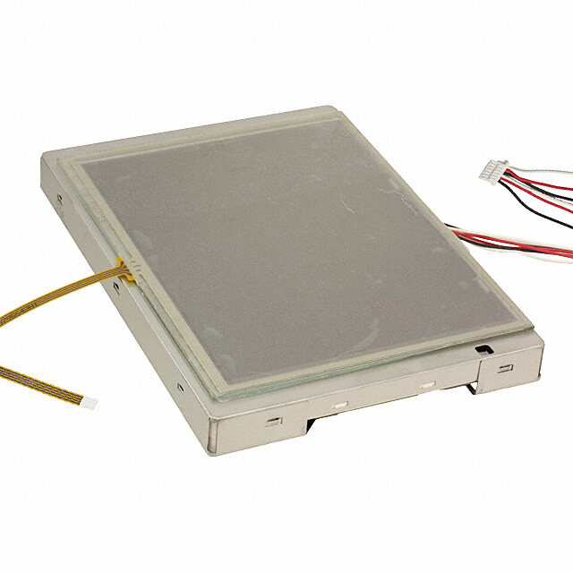
| 描述/功能 | Credit card size VM800C module, supports 3.3 V, 5 V MCU adapter board, with FPC/FFC 40 LCD connector, 4.3 in TFT LCD display panel preinstalled |
| 文字颜色 | - |
| 显示模式 | 可传导的 |
| 显示类型 | TFT |
| 标准包装 | 5 |
| 点像素 | 480 x 272 |
| 点尺寸 | - |
| 点间距 | - |
| 用于 | FT800 |
| 相关产品 | /product-detail/zh/VA800A-SPI/768-1211-ND/4487376/product-detail/zh/VA-PSU-UK1/768-1190-ND/4332013/product-detail/zh/VA-PSU-EU1/768-1189-ND/4332012/product-detail/zh/FT800Q-R/768-1185-6-ND/4332011/product-detail/zh/FT800Q-R/768-1185-1-ND/4332010/product-detail/zh/VA-FC-STYLUS1/768-1188-ND/4332009/product-detail/zh/VA-FC-1M-BLW/768-1187-ND/4332008/product-detail/zh/VA-FC-1M-BKW/768-1186-ND/4332007/product-detail/zh/VA-PSU-US1/768-1191-ND/4332006/product-detail/zh/FT800Q-R/768-1185-2-ND/4331996/product-detail/zh/C232HM-EDHSL-0/768-1105-ND/2714140/product-detail/zh/C232HM-DDHSL-0/768-1106-ND/2714139 |
| 类型 | Embedded Video Engine |
| 系列 | FT800 |
| 背光 | LED - 白 |
| 背景颜色 | - |

/MFG_VM800C43A-D%2045%20DEGREE.jpg)


/VM801P50A-BK.jpg)


- 商务部:美国ITC正式对集成电路等产品启动337调查
- 曝三星4nm工艺存在良率问题 高通将骁龙8 Gen1或转产台积电
- 太阳诱电将投资9.5亿元在常州建新厂生产MLCC 预计2023年完工
- 英特尔发布欧洲新工厂建设计划 深化IDM 2.0 战略
- 台积电先进制程称霸业界 有大客户加持明年业绩稳了
- 达到5530亿美元!SIA预计今年全球半导体销售额将创下新高
- 英特尔拟将自动驾驶子公司Mobileye上市 估值或超500亿美元
- 三星加码芯片和SET,合并消费电子和移动部门,撤换高东真等 CEO
- 三星电子宣布重大人事变动 还合并消费电子和移动部门
- 海关总署:前11个月进口集成电路产品价值2.52万亿元 增长14.8%

/VM800C43A-D.jpg)


PDF Datasheet 数据手册内容提取
VM800C Datash eet Version 1.2 Document Reference No.: FT_000844 Clearance No.: FTDI# 345 FTDI Chip VM800C Datasheet Embedded Video Engine Credit Card Board General Purpose Multi Media Controller 1 Introduction 1.1 Features The VM800C is a development module for The VM800C utilises the FTDI FT800 FTDI’s FT800, which is used to develop and Embedded Video Engine. Graphic, audio and demonstrate the functionality of the FT800 touch features of the FT800 can be accessed Embedded Video Engine, EVE. This module with the VM800C. For a full list of the FT800’s behaves as an SPI slave, and requires a SPI features please see the FT800 datasheet. Master for proper micro-controller interfacing The VM800C has the following features: and system integration. Ready to use LCD module VM800C modules support 3 different LCD Part types with LCDs supporting resistive panel size options. Users can also connect to touch with pressure sensing. different LCD screens as long as they meet the FT800 technical specification and fit the On board LCD backlight LED Driver VM800C LCD connector. Supports mono audio output VM800C35A-D, 3.3/5V micro- controller adaptor card with 3.5” LCD On board audio power amplifier and micro touch display speaker VM800C43A-D, 3.3/5V micro- controller adaptor card with 4.3” LCD Flexible power supply. Powering the VM800C touch display using either a 2.1mm power jack , SPI master connector or via USB Micro-B port VM800C50A-D, 3.3/5V micro- controller adaptor card with 5.0” LCD 5 V tolerant buffers when used with a 5V SPI VMFT800C35A-N, 3.3/5V micro- Master. controller adaptor card, with 3.5” LCD connector but no display VMFT800C43A-N, 3.3/5V micro- controller adaptor card, with 4.3/5.0” LCD connector but no display Use of FTDI devices in life support and/or safety applications is entirely at the user’s risk, and the user agrees to defend, indemnify and hold harmless FTDI from any and all damages, claims, suits or expense resulting from such use.
VM800C Datasheet Version 1.2 Document Reference No.: FT_000844 Clearance No.: FTDI# 345 Ordering Information 2 Note that the kits below require a 5V/1A power supply. It is NOT provided in the development kit, but is offered as an optional accessory, as is the USB to SPI cable, with the following part types: Part No. Description VM800C35A-N Credit Card Size VM800C module, supports 3.3/5v MCU Adapter Board, with FPC/FFC 54 LCD connector. No display is provided. VM800C43A-N Credit Card Size VM800C module, supports 3.3/5v MCU Adapter Board, with FPC/FFC 40 LCD. No display is provided. VM800C35A-D Credit Card Size VM800C module, supports 3.3/5v MCU Adapter Board, with FPC/FFC 54 LCD connector, 3.5 inch TFT LCD display panel preinstalled. Credit Card Size VM800C module, supports 3.3/5v MCU Adapter Board, with FPC/FFC 40 LCD connector, 4.3 inch TFT LCD display VM800C43A-D panel preinstalled. Credit Card Size VM800C module, supports 3.3/5v MCU Adapter Board, with FPC/FFC 40 LCD connector, 5.0 inch TFT LCD display VM800C50A-D panel preinstalled. VA-PSU-UK1 Accessory - UK Model 5V/1A USB Power Supply (Mfr # JX-B0520C-1-B) VA-PSU-US1 Accessory - US Model 5V/1A USB Power Supply (Mfr # JX-B0520B-1-B) VA-PSU-EU1 Accessory - EU Model 5V/1A USB Power Supply (Mfr # JX-B0520A-1-B) Accessory - High Speed Micro USB to SPI adapter for BASIC boards VA800A-SPI based on FT232H MPSSE design VA-FC-1M-BKW Accessory - Flat USB A to Micro B Cable 1M- Black and White VA-FC-1M-BLW Accessory - Flat USB A to Micro B Cable 1M- Blue and White VA-FC-STYLUS1 Accessory - Resistive Touch Screen Pen Stylus Table 2-1 – Ordering information 2 Copyright © 2014 Future Technology Devices International Limited
VM800C Datasheet Version 1.2 Document Reference No.: FT_000844 Clearance No.: FTDI# 345 Table of Contents 1 Introduction ................................................................................... 1 1.1 Features ........................................................................................................ 1 2 Ordering Information ..................................................................... 2 3 Hardware Description ..................................................................... 4 3.1 VM800C board ............................................................................................... 4 3.2 Physical Descriptions .................................................................................... 5 3.2.1 PCB layout ................................................................................................ 5 3.2.2 VM800C Connectors ................................................................................... 6 4 Board Schematics ......................................................................... 10 5 Hardware Setup Guide .................................................................. 14 5.1 Power Configuration ................................................................................... 14 5.2 MPSSE Setup ............................................................................................... 14 5.3 Arduino® Setup........................................................................................... 16 6 Mechanical Dimensions ................................................................ 17 6.1 VM800C35A - 3.5” Dimensions .................................................................... 17 6.2 VM800C43A - 4.3” Dimensions .................................................................... 19 6.3 VM800C50A - 5.0” Dimensions .................................................................... 21 7 Specifications ............................................................................... 23 7.1 Optical Specification ................................................................................... 23 8 Contact Information ..................................................................... 26 Appendix A - References ....................................................................................... 20 Appendix C – Revision History ............................................................................... 22 3 Copyright © 2014 Future Technology Devices International Limited
VM800C Datasheet Version 1.2 Document Reference No.: FT_000844 Clearance No.: FTDI# 345 Hardware Description 3 Please refer to section 3.2.2 for connector settings. Some VM800C jumpers must be set to work properly with your system. 3.1 VM800C board Figure 3-1 – VM800C board profile 3.5” display version Figure 3-2 - VM800C board profile 4.3”/5” display version 4 Copyright © 2014 Future Technology Devices International Limited
VM800C Datasheet Version 1.2 Document Reference No.: FT_000844 Clearance No.: FTDI# 345 The VM800C module is intended for direct use into existing applications that require a display.This module is suitable for interfacing with an external microcontroller that has a SPI Master channel. The VM800C module PCB comes in 2 types , 3.5 inch as well as a 4.3/5 inch model. The difference between the 2 models is the flex cable receptical of the LCD. The 3.5 inch LCD uses a 54 pin receptical, whereas the 4.3/5 inch model uses a 40 pin receptical. The main functions of the VM800C are as follows: Micro USB, SPI connector or 2-pin connector for power supply 3.3V regulator : Takes 5V input and outputs 3.3V for on-board circuits LCD touch screen panel LCD backlight driver. On board back light driver has over voltage protection (OVP). Backlight drive current Part No OVP (v) (mA) VM800C35A-N 34 20 VM800C43A-N 34 32 VM800C35A-D 24 20 VM800C43A-D 24 32 VM800C50A-D 24 32 Table 3-1 LED backlight drive OVP and current 5V tolerant buffers between the SPI master interface and the Slave interface of the FT800 o SPI timing requirement can be referred to FT800 datasheet. The on board level convert buffers introduce additional delay. The actual maximum SPI clock frequency depends on the host system timing and connection cable length to VM800C. 3 stage audio filter and power amplifier 8Ω speaker Audio line out option 3.2 Physical Descriptions 3.2.1 PCB layout The VM800C module is 85.6 x 54.1mm, four-layer printed circuit board. Board thickness is approximately 1.6mm. 5 Copyright © 2014 Future Technology Devices International Limited
VM800C Datasheet Version 1.2 Document Reference No.: FT_000844 Clearance No.: FTDI# 345 Figure 3-3 - VM800C module top view, 3.5 inch display version 3.2.2 VM800C Connectors Connectors and jumpers are described in the following sections. CN1- 2-pin power connector 2 pin connector for 5V/3.3V power input to the board. Alternative to Micro USB connector. Pin No. Name Type Description 1 VCC P 5V or 3.3V DC power supply 2 GND P Ground Table 3-2 – CN1 Pinout CN2- Micro USB Receptical This receptical is strictly for 5V input to power the board. There is no USB Functionality Pin No. Name Type Description 1 VBUS P 5V power supply 2 NC NA No connection 3 NC NA No connection 4 NC NA No connection 5 GND P Ground Table 3-3 – CN2 Pinout J1- LCD Flex Cable connector This connector is the interface between the FT800 IC and the LCD Module. 6 Copyright © 2014 Future Technology Devices International Limited
VM800C Datasheet Version 1.2 Document Reference No.: FT_000844 Clearance No.: FTDI# 345 Signal Pin No Pin No Description (3.5”) (4.3/5.0”) LED K 1,2 1 LED Cathode LED A 3,4 2 LED Cathode General purpose output pin for 8 LCD Display Enable, push-pull output, 4/8mA sink/source DISP 31 current. Control by writing to Bit 7 of REG_GPIO register. LCD Horizontal Sync, push-pull output, 4/8mA sink/source HSYNC 36 32 current. LCD Vertical Sync, push-pull output, 4/8mA sink/source VSYNC 37 33 current. LCD Pixel Clock, push-pull output, 4/8mA sink/source DCLK 38 30 current. LCD Data Enable, push-pull output, 4/8mA sink/source DE 52 34 current. Bit 2 of Red RGB signals, push- pull output, 4/8mA sink/source R2 14 7 current. Bit 3 of Red RGB signals, push- R3 15 8 pull output, 4/8mA sink/source current. Bit 4 of Red RGB signals, push- R4 16 9 pull output, 4/8mA sink/source current. Bit 5 of Red RGB signals, push- R5 17 10 pull output, 4/8mA sink/source current. Bit 6 of Red RGB signals, push- R6 18 11 pull output, 4/8mA sink/source current. Bit 7 of Red RGB signals, push- R7 19 12 pull output, 4/8mA sink/source current. 15 Bit 2 of Green RGB signals, G2 22 push-pull output, 4/8mA sink/source current 16 Bit 3 of Green RGB signals, G3 23 push-pull output, 4/8mA sink/source current 17 Bit 4 of Green RGB signals, G4 24 push-pull output, 4/8mA sink/source current 18 Bit 5 of Green RGB signals, G5 25 push-pull output, 4/8mA sink/source current G6 26 19 Bit 6 of Green RGB signals, 7 Copyright © 2014 Future Technology Devices International Limited
VM800C Datasheet Version 1.2 Document Reference No.: FT_000844 Clearance No.: FTDI# 345 Signal Pin No Pin No Description (3.5”) (4.3/5.0”) push-pull output, 4/8mA sink/source current 20 Bit 7 of Green RGB signals, G7 27 push-pull output, 4/8mA sink/source current 23 Bit 2 of Blue RGB signals, push- B2 30 pull output, 4/8mA sink/source current. 24 Bit 3 of Blue RGB signals, push- B3 31 pull output, 4/8mA sink/source current. 25 Bit 4 of Blue RGB signals, push- B4 32 pull output, 4/8mA sink/source current. 26 Bit 5 of Blue RGB signals, push- B5 33 pull output, 4/8mA sink/source current. 27 Bit 6 of Blue RGB signals, push- B6 34 pull output, 4/8mA sink/source current. Bit 7 of Blue RGB signals, push- 28 pull output, 4/8mA sink/source B7 35 current. XP 48 37 X +ve touch YM 49 38 Y –ve touch XM 50 39 X –ve touch YP 51 40 Y +ve touch 3V3 9,10,11,41,42 4 3V3 Power GND 12,13,20,21,28,2953,54 3,5,6,13,14,21,22,29,36 Ground NC 5,6,7,39,40,43,44,45,46,47 35 No connect Table 3-4 – J1 Pinout J2 - Selection between lineout or loop back into the power amplifier. Selection between audio lineout or loop back into the power amplifier. (Footprint only, JP2 next to J2 is connected by default for on board amplifier and on board mini speaker). If J2 is soldered and used for audio output selection, JP2 needs to be removed. Pin No. Name 1 -2 Audio amp enabled 2-3 Audio amp mute, Audio lineout on pin 1 Table 3-5 – J2 Pin Options J3 – SP+ Audio speaker +ve from the onboard amplifier. J4 – SP- 8 Copyright © 2014 Future Technology Devices International Limited
VM800C Datasheet Version 1.2 Document Reference No.: FT_000844 Clearance No.: FTDI# 345 Audio speaker -ve from the onboard amplifier. J5- SPI Interface This is the interface where the SPI control and data signals are routed. There are also power and ground pins on this interface. Note J5 is not soldered on the VM800C board by default. Pin No. Name Type Description 1 SCLK I SPI Clock input 2 MOSI I Master Out Slave in 3 MISO O Master In Slave out 4 CS# I Chip select , active low Host interrupt open drain output, active low. 5 INT# OD On board 47kΩ pull-up to 3.3V. 6 PD# I Active low power down input. 7 5V P 5V power supply 8 3.3V P 3.3V power supply 9 GND P Ground 10 GND P Ground Table 3-6 – J5 Pinout JP1- Audio Amplifier Power Select This jumper provides the option to select the power supply voltage for the onboard power amplifier. Pin No. Name 1-2 3V3 selected 2-3 5V selected Table 3-7 – JP1 Pin options *This needs to be configured before audio can be heard JP2 – On board amplifier enable Solder connection fitted by default JP3 - On board amplifier mute Solder connection not fited by default SW1 – Power source select Pin No. Name 1-2 Power from CN1 2-3 Power from CN2 Table 3-8 – JP1 Pin options 9 Copyright © 2014 Future Technology Devices International Limited
VM800C Datasheet Version 1.2 Document Reference No.: FT_000844 Clearance No.: FTDI# 345 Board Schematics 4 3V3 3V3 U2 R2 J1 LCD1 5MMVISNPCOICSDTSSOK###I2 U4VMCSPIMNICDSNIOTSK##S#ONIL1R30VG1O5NSTU3DW2VT2111113032041271549368MC0.7117UuF3AGOAOOAAOVYYYY31NE2EE43EC1423V1243CD77344LLGGVCCOOOONNXXCYYYYAAAAEEEEDDC11142312431243C022.8155uF13168271541191C241320.121GnFN3DVFFFF3TTTTFFC88880000TTS000088#____00PSMC00DC__SOIMK##NSITIS#O LEAFFFFAFFDTTTTTTUUA888888DD000000000000IIOO______SMMCPI__NCDLSSIOTHK#S#S#ODIN# R147k R247k GR4N73kDVCR4O74kRE 3VC2371pFG111N123456789012DU1AGSMMCGGVMIP1NCDSUNPPCY2IOOTSK_IIMCDD149SDOOnOLIGNDII/HE01OS//O/1348SSS/zASXTIR2_DACAGL14471KA0XTOR32N1546DGNDR4C2164572VCC3V3R5p1744FVCORER61843VCC3V3R719423XPG2V420413.CYPG3732140uGFXMG42239N0YMG5D.C233814GNDG6uF2437VBACKLIGHTG7CO4VHR.C7DSSEF5uDGYYCTGFIN8NNDLNBBBBBBS00DKCCEPD7654320.C1Q6uF222223333333567890123456GND RRRRRGGGGGGBBBBBBDDHVDBYXYX34567234567C234567CISSEMMPPSYYKLPKNNLCC LRRRLRRRGGGGGGBBBBBBDDHVEE246357234567234567CISSSYXYXDDDYYLPMMPPEKAKNNRRGGBBCC010101 11111111112222222222333333333344444444445555501234567890123456789012345678901234567890123412345678900 12345678911111111112222222222333333333344444444445555500012345678901234567890123456789012345678901234 123456789111111111122222222223333333333444444444455555012345678901234567890123456789012345678901234AT0LLLLNNNRSSSHVDNNVVNNNNNXYXDGGYBBBBBBBBGGGGGGGGRRRRRRRR3PPPEEEE5E0123456701234567CCCSSOCCDDCCCCCRDLENNU01234567ECDGDDDDSYYNTDDDDNKAE[[[[T----NNCLRBTKKAAAT-CCLeo0iogfp7Kttht]E]otD]m3] BCKL 3 EN4AGND8PGND9EP FB 6 D11N4148 R54k7 LEDKLED Current Sense R7 AAUUDDIIGOON__DLSHDN#0.5B-A5U4PDBIOXA_USDHIDON_L# C9 C10 MIC2289-24YML 4.7R :=20mA R6 R7 C12 10uF 0.1uF 10k/1% 4R7 0.22uF GND GND GND GND GND GND Figure 4-1 - VM800C35 ( 3.5” Version) 10 Copyright © 2014 Future Technology Devices International Limited
VM800C Datasheet Version 1.2 Document Reference No.: FT_000844 Clearance No.: FTDI# 345 3V3 3V3 U2 R2 J1 LCD1 MMISNPCOICSDTSSKO###I MCSPIMNCDSIOTSK##S#OI GN3DV11111332041271549368C0.71UuF3AGOAOOAAOVYYYY31NE2EE43EC1423V1243CD77344LLGGVCCOOOONNXXCYYYYAAAAEEEEDDC11142312431243C022.8155uF1316827154119141320GN3DVFFFF3TTTTFFC88880000TTS000088#____00PSMC00DC__SOIMK##NSIITS#O AFFFFAFFTTTTTTUU888888DD000000000000IIOO______SMMCPI__NCDLSSIOTHK#S#S#ODIN# R147k R247k R473kVCR4O74kRE 3VC2371pF111123456789012 U1AGSMMCGGVMIPN1CDSUNPPCY2IOOTSK_IIMCDD149SDOOnOLIGNDII/HE01OS//O/1348SSS/zASXTIR2_DACAL14471KA0XTOR321546GNDR4C2164572VCC3V3R5p1744FVCORER61843VCC3V3R71942XPG22041YPG32140XMG42239YMG52338GNDG62437BACKLIGHTG7 VHDSSFDGYYCTINNN8DLBBBBBBS0DKCCEP7654320Q 222223333333567890123456 RRRRRGGGGGGBBBBBBDDHVDBYXYX34567234567C234567CISSEMMPPSYYKLPKNNLCC LRRRLRRRGGGGGGBBBBBBYXYXDDHVDEE246357234567234567MMPPCISSESDDYYLPKAKNNRRGGBBCC010101 1111111111222222222233333333334012345678901234567890123456789012345678900 1234567891111111111222222222233333333334000123456789012345678901234567890A1234567891111111111222222222233333333334T0123456789012345678901234567890043VVHVPDNVXYXDGGYRRRRRRRRGGGGGGGGBBBBBBBBGBC0123456701234567LLSSICD112ENN201234567N3S[[[[L5YYEEDDDDLRBTP-KDDNN1eoiog5fp-+tCCthtl]]o-t1]m0] 3V3 VCORE GND 0.5B-40PBS GND GND GND C3 C4 C5 C6 GND 4.7uF0.1uF 4.7uF0.1uF 5V L1 GND GND NR3015T220M U4 LEDA 2 VIN SW 7 C11 VOUT 1 2.2nF BCKL 3 EN AGNDPGNDEP FB 6 D1 R54k7 LEDK 1N4148 LED Current Sense R7 489 3R=32mA C9 C10 MIC2289-24YML R6 R7 C12 10uF 0.1uF 10k/1% 3R 0.22uF GND GND GND GND GND GND Figure 4-2 - VM800C43/VM800C50 (4.3”/5.0” Version) 11 Copyright © 2014 Future Technology Devices International Limited
VM800C Datasheet Version 1.2 Document Reference No.: FT_000844 Clearance No.: FTDI# 345 3V3 k k k k k k 7 7 7 7 7 7 4 4 4 4 4 4 5V 3V3 5 6 7 8 9 0 2 2 2 2 2 3 R R R R R R J5 R19 33R SCK 1 SCK R20 33R MOSI 2 MOSI R21 33R MISO 3 MISO R22 33R CS# 4 CS# R23 33R INT# 5 INT# R24 33R PD# 6 PD# 7 8 C27 C28 C29 C30 C31 C32 9 6x10pF 10 GND GND XL2 To bypass 3.3V regulator place jumper Shunt 0.1" on pins J5-7 and J5-8. VBUS SW1 SS-1290AP 5V U7 3V3 AP1117E33G-13 CN1 VBUS 3 Vin Vout 2 1 CN2 2 GND 1 VBUS 2 19108 C24 1 C25 C26 D- D+ 3 0.1uF 0.1uF 10uF 4 ID 5 GND GND GND GND GND GND R18 USB Micro-B 0R GND Figure 4-3 – VM800C SPI Interface and IO 12 Copyright © 2014 Future Technology Devices International Limited
VM800C Datasheet Version 1.2 Document Reference No.: FT_000844 Clearance No.: FTDI# 345 AUD_3V3 U5 5 AUDIO_L AUDIO_L R8 33R 2 OE 4 R9 1k R10 1k R11 1k C16 0.47uF AUDIO_L_out 1 C13 C14 C15 AUD_3V3 3 4.7nF 4.7nF 4.7nF JP2 C17 J2 JP2-Audio Amp. Enabled 0.1uF AGND SN74LVACG1NGD125DBVR AGND AGND AGNRD12 JP3 123 JP3-Audio Amp. Mute 10k/1% AUD_3V3 Header 0.1" R13 20k/1% U6 AGND AUDIO_SHDN# AUDIO_SHDN# R16 33R 1234 SBIINNHY+-DPANSSVGGVVDNNOODDD+- 56789 SSPP-+ JJ43 S1WP1/8Ohm TPA6205A1 R14 R15 20k/1% 10k/1% R17 C18 C19 C20 47k 0.47uF 0.22uF 1uF AGND AGND AGND AGNDAGND 5V 3V3 AUD_3V3 FB1 XL1 JP1 1 600R/1A 2 C21 C22 C23 Shunt 2.0mm 3 FB2 100uF 0.1uF 10nF Jumper 2.0mm 600R/1A GND AGND Max peak current ~400mA for 8-ohm speaker Figure 4-4 – VM800C Audio 13 Copyright © 2014 Future Technology Devices International Limited
VM800C Datasheet Version 1.2 Document Reference No.: FT_000844 Clearance No.: FTDI# 345 Hardware Setup Guide 5 5.1 Power Configuration There are 5 methods of powering the VM800C board. 1) USB Power(5V) - Connect USB power through micro-USB cable to CN2 2) DC IN(5V) - Connect 5V to CN1 3) DC IN(3.3V) - Connect 3.3V to CN1 and short J5 pin 7 and 8 4) J5 Power(5V) - Connect 5V to J5 pin 7 5) *J5 Power(3.3V) - Connect 3.3V to J5 pin 7 and 8 *Warning: Applying 5 V accidently in this mode may cause permanent demage to the VM800C module. The following table summarise how to power the VM800C board using the various methods. Power Method CN2 CN1 J5 Pin 7 J5 Pin 8 SW1 USB Power 5V N/C N/C N/C Short pin 2-3 DC IN(5V) N/C 5V N/C N/C Short pin 1-2 DC IN(3.3V) N/C 3.3V SHORT Short pin 1-2 J5 Power(5V) N/C N/C 5V N/C Any Position J5 Power (3.3V) N/C N/C 3.3V Any Position Table 5-1 Board power configuration 5.2 MPSSE Setup To give a quick start with the VM800C development board, a Windows based Sample Application and demo applications are provided for users to experiment and experience the FT800 in the VM800C system. The following paragraphs provide a short description for development procedures. MPSSE is a “multi purpose synchronous serial engine” interface available in some FTDI device (e.g. FT2232D, FT232H, FT2232H anf FT4232H). This engine allows users to bridge from a USB port on a PC to an I2C or SPI interface. Sample code is available for driving the FT800 over this interface with a FT232H device that has been integrated into a cable. This device is available in the VA800A-SPI board, or C232HM-EDHSL-0(5V) cable or C232HM-DDHSL-0(3.3V) cable. VA800A-SPI is a MPSSE module accessory which can connect to the VM800C modules directly. Detailed information of VA800A-SPI can be found at: http://www.ftdichip.com/VM800B.htm. More information about MPSSE cables may be found at: http://www.ftdichip.com/Support/Documents/DataSheets/Cables/DS_C232HM_MPSSE_CABLE.pdf. In this section it is assumed the 5V version of the MPSSE cable (FTDI part no C232HM-EDHSL-0) is used. In case a 3.3V version of the MPSSE cable (FTDI part no C232HM-DDHSL-0) is available, the setup is similar except for the power pin connection. Refer to table 5-1 for board power configuration. 14 Copyright © 2014 Future Technology Devices International Limited
VM800C Datasheet Version 1.2 Document Reference No.: FT_000844 Clearance No.: FTDI# 345 Figure 5-1 – VM800C connects to PC via VA800A-SPI or MPSSE cable. Hardware Setup VA800A-SPI Solder a 10 position single row pin header to J5 footprint of the VM800C board Connect VA800A-SPI to the VM800C module in the correct orientation. Connect USB cable (e.g. FTDI accessory VA-FC-1M-BKW or VA-FC-1M-BLW) from the VA800A- SPI to the PC USB host port. VA800A-SPI will supply power to VM800C after MPSSE driver is properly loaded and the USB host completed USB device configuration. Hardware Setup MPSSE Cable Solder a 10 position single row pin header to J5 footprint of the VM800C board Configure JP1 to either 3.3V or 5V o Power Audio Amp by 3.3V : JP1 pin1 and pin 2 close o Power Audio Amp by 5V : JP1 pin2 and pin 3 close (5V board supply must be provided) Connect MPSSE leads to VM800C board’s J5( SPI interface) in accordance with Table 5-2 Plug MPSSE cable to PC USB port Software Setup Download PC Base MPSSE software. MPSSE cable and driver information can be found at http://www.ftdichip.com/Products/Cables/USBMPSSE.htm. Launch the Sample Application based on MPSSE from PC For more information on utilizing the VM800C development system with the MPSSE cable and Sample Application, refer to AN_245. 15 Copyright © 2014 Future Technology Devices International Limited
VM800C Datasheet Version 1.2 Document Reference No.: FT_000844 Clearance No.: FTDI# 345 Further documentation associated with the VM800C development system and design flow can be found at following link: http://www.ftdichip.com/VM800C.htm The FT800 Programming Guide describes the programming code and formats used by the FT800. The Sample Application is a well-formatted, and documented program that illustrates the Programming Guide, and provides numerous design examples and reference code demonstrations. J5 Pin number J5 Signal MPSSE pin number MPSSE Signal MPSSE Lead Color 1 SCK 2 SK ORANGE 2 MOSI 3 DO YELLOW 3 MISO 4 DI GREEN 4 CS# 5 CS BROWN 5 INT# 7 GPIOL1 PURPLE 6 PD# 9 GPIOL3 BLUE 7 5V 1 VCC RED 8 3.3V - - - 9 GND 10 GND Black 10 GND - - - Table 5-2 – MPSSE cable (C232HM-EDHSL-0) connection 5.3 Arduino® Setup Sample codes and demo applications are provided to users who want to connect VM800C to a MCU. FTDI provides sample source code, Sample Application notes (AN_246) and a ready to run demo based on Arduino® platform. Further documentation associated with the VM800C development system and design flow can be found at http://www.ftdichip.com/VM800C.htm. Applicaton note, AN_246, provides a reference guide for utilizing the VM800C development systems with the Sample Application software and Arduino Pro platform. The FT800 Programming Guide describes the programming code and formats used by the FT800. The Sample Application is a well-formatted, and documented program that illustrates the Programming Guide, and provides numerous design examples and reference code demonstrations. 16 Copyright © 2014 Future Technology Devices International Limited
VM800C Datasheet Version 1.2 Document Reference No.: FT_000844 Clearance No.: FTDI# 345 Mechanical Dimensions 6 6.1 VM800C35A - 3.5” Dimensions Figure 6-1 – VM800C35A PCB dimensions 17 Copyright © 2014 Future Technology Devices International Limited
VM800C Datasheet Version 1.2 Document Reference No.: FT_000844 Clearance No.: FTDI# 345 Figure 6-2 – VM800C35A Display dimensions 18 Copyright © 2014 Future Technology Devices International Limited
VM800C Datasheet Version 1.2 Document Reference No.: FT_000844 Clearance No.: FTDI# 345 6.2 VM800C43A - 4.3” Dimensions Figure 6-3 – VM800C43A PCB dimensions 19 Copyright © 2014 Future Technology Devices International Limited
VM800C Datasheet Version 1.2 Document Reference No.: FT_000844 Clearance No.: FTDI# 345 Figure 6-4 – VM800C43A Display dimensions. 20 Copyright © 2014 Future Technology Devices International Limited
VM800C Datasheet Version 1.2 Document Reference No.: FT_000844 Clearance No.: FTDI# 345 6.3 VM800C50A - 5.0” Dimensions Figure 6-5 – VM800C50A PCB dimensions. 21 Copyright © 2014 Future Technology Devices International Limited
VM800C Datasheet Version 1.2 Document Reference No.: FT_000844 Clearance No.: FTDI# 345 Figure 6-6 – VM800C50A Display dimensions 22 Copyright © 2014 Future Technology Devices International Limited
VM800C Datasheet Version 1.2 Document Reference No.: FT_000844 Clearance No.: FTDI# 345 Specifications 7 7.1 Optical Specification Table 7-1 - 3.5” TFT Optical specification 23 Copyright © 2014 Future Technology Devices International Limited
VM800C Datasheet Version 1.2 Document Reference No.: FT_000844 Clearance No.: FTDI# 345 Table 7-2 - 4.3” TFT Optiocal Specification 24 Copyright © 2014 Future Technology Devices International Limited
VM800C Datasheet Version 1.2 Document Reference No.: FT_000844 Clearance No.: FTDI# 345 Table 7-3 - 5” TFT Optiocal Specification 25 Copyright © 2014 Future Technology Devices International Limited
VM800C Datasheet Version 1.2 Document Reference No.: FT_000844 Clearance No.: FTDI# 345 Contact Information 8 Head Office – Glasgow, UK Branch Office – Tigard, Oregon, USA Unit 1, 2 Seaward Place, Centurion Business Park 7130 SW Fir Loop Glasgow G41 1HH Tigard, OR 97223 United Kingdom USA Tel: +44 (0) 141 429 2777 Tel: +1 (503) 547 0988 Fax: +44 (0) 141 429 2758 Fax: +1 (503) 547 0987 E-mail (Sales) sales1@ftdichip.com E-Mail (Sales) us.sales@ftdichip.com E-mail (Support) support1@ftdichip.com E-Mail (Support) us.support@ftdichip.com E-mail (General Enquiries) admin1@ftdichip.com E-Mail (General Enquiries) us.admin@ftdichip.com Branch Office – Taipei, Taiwan Branch Office – Shanghai, China 2F, No. 516, Sec. 1, NeiHu Road Room 1103, No. 666 West Huaihai Road, Taipei 114 Changning District, Shanghai, 200052 Taiwan , R.O.C. China Tel: +886 (0) 2 8797 1330 Tel: +86 (0)21 6235 1596 Fax: +886 (0) 2 8751 9737 Fax: +86 (0)21 6235 1595 E-mail (Sales) tw.sales1@ftdichip.com E-mail (Sales) cn.sales@ftdichip.com E-mail (Support) tw.support1@ftdichip.com E-mail (Support) cn.support@ftdichip.com E-mail (General Enquiries) tw.admin1@ftdichip.com E-mail (General Enquiries) cn.admin@ftdichip.com Web Site http://ftdichip.com Distributor and Sales Representatives Please visit the Sales Network page of the FTDI Web site for the contact details of our distributor(s) and sales representative(s) in your country. System and equipment manufacturers and designers are responsible to ensure that their systems, and any Future Technology Devices International Ltd (FTDI) devices incorporated in their systems, meet all applicable safety, regulatory and system-level performance requirements. All application-related information in this document (including application descriptions, suggested FTDI devices and other materials) is provided for reference only. While FTDI has taken care to assure it is accurate, this information is subject to customer confirmation, and FTDI disclaims all liability for system designs and for any applications assistance provided by FTDI. Use of FTDI devices in life support and/or safety applications is entirely at the user’s risk, and the user agrees to defend, indemnify and hold harmless FTDI from any and all damages, claims, suits or expense resulting from such use. This document is subject to change without notice. No freedom to use patents or other intellectual property rights is implied by the publication of this document. Neither the whole nor any part of the information contained in, or the product described in this document, may be adapted or reproduced in any material or electronic form without the prior written consent of the copyright holder. Future Technology Devices International Ltd, Unit 1, 2 Seaward Place, Centurion Business Park, Glasgow G41 1HH, United Kingdom. Scotland Registered Company Number: SC136640 26 Copyright © 2014 Future Technology Devices International Limited
VM800C Datasheet Version 1.2 Document Reference No.: FT_000844 Clearance No.: FTDI# 345 Appendix A - References For module documentations, please refer to URL below: www.ftdichip.com/VM800C.htm FT800 datasheet: DS_FT800_Embedded_Video_Engine FT800 software programming guide: FT800_Programmer_Guide FT800 sample application notes: AN_245_VM800CB_SampleAPP_PC_Introduction AN_246_VM800CB_SampleAPP_Arduino_Introduction C232HM-DDHSL-0 datasheet: http://www.ftdichip.com/Support/Documents/DataSheets/Cables/DS_C232HM_MPSSE_CABLE.pdf D2xx Programmers Guide: http://www.ftdichip.com/Support/Documents/ProgramGuides/D2XX_Programmer's_Guide(FT_000071).p df AN_108: Command Processor for MPSSE and MCU Host Bus Emulation Modes http://www.ftdichip.com/Support/Documents/AppNotes/AN_108_Command_Processor_for_MPSSE_and_ MCU_Host_Bus_Emulation_Modes.pdf 20 Copyright © 2014 Future Technology Devices International Limited
VM800C Datasheet Version 1.2 Document Reference No.: FT_000844 Clearance No.: FTDI# 345 Appendix B - List of Figures and Tables List of Figures Figure 3-1 – VM800C board profile 3.5” display version ............................................................................. 4 Figure 3-2 - VM800C board profile 4.3”/5” display version ......................................................................... 4 Figure 3-3 - VM800C module top view, 3.5 inch display version ................................................................ 6 Figure 4-1 - VM800C35 ( 3.5” Version) ......................................................................................................... 10 Figure 4-2 - VM800C43/VM800C50 (4.3”/5.0” Version) ............................................................................... 11 Figure 4-3 – VM800C SPI Interface and IO .................................................................................................. 12 Figure 4-4 – VM800C Audio .......................................................................................................................... 13 Figure 5-1 – VM800C connects to PC via VA800A-SPI or MPSSE cable. ................................................. 15 Figure 6-1 – VM800C35A PCB dimensions ................................................................................................. 17 Figure 6-2 – VM800C35A Display dimensions ............................................................................................ 18 Figure 6-3 – VM800C43A PCB dimensions ................................................................................................. 19 Figure 6-4 – VM800C43A Display dimensions. ........................................................................................... 20 Figure 6-5 – VM800C50A PCB dimensions. ................................................................................................ 21 Figure 6-6 – VM800C50A Display dimensions ............................................................................................ 22 List of Tables Table 2-1 – Ordering information ................................................................................................................... 2 Table 3-1 LED backlight drive OVP and current ........................................................................................... 5 Table 3-2 – CN1 Pinout .................................................................................................................................... 6 Table 3-3 – CN2 Pinout .................................................................................................................................... 6 Table 3-4 – J1 Pinout ....................................................................................................................................... 8 Table 3-5 – J2 Pin Options .............................................................................................................................. 8 Table 3-6 – J5 Pinout ....................................................................................................................................... 9 Table 3-7 – JP1 Pin options ............................................................................................................................ 9 Table 3-8 – JP1 Pin options ............................................................................................................................ 9 Table 5-1 Board power configuration .......................................................................................................... 14 Table 5-2 – MPSSE cable (C232HM-EDHSL-0) connection ........................................................................ 16 Table 6-1 - 3.5” TFT Optical specification ................................................................................................... 23 Table 6-2 - 4.3” TFT Optiocal Specification................................................................................................. 24 Table 6-3 - 5” TFT Optiocal Specification .................................................................................................... 25 21 Copyright © 2014 Future Technology Devices International Limited
VM800C Datasheet Version 1.2 Document Reference No.: FT_000844 Clearance No.: FTDI# 345 Appendix C – Revision History Document Title: DS_VM800C Document Reference No.: FT_000844 Clearance No.: FTDI# 345 Product Page: http://www.ftdichip.com/eve.htm Document Feedback: Send Feedback Version 1.0 Initial Datasheet relased 16/08/13 Version 1.1 Added Section 6 Mechanical Dimensions of PCBs and displays 10/02/14 Version 1.2 Updated the optical characteristics for the 4.3” and 5” displays 12/06/14 22 Copyright © 2014 Future Technology Devices International Limited