
 Datasheet下载
- 型号: VJ0603A470JXAAC
- 制造商: Vishay
- 库位|库存: xxxx|xxxx
- 要求:
| 数量阶梯 | 香港交货 | 国内含税 |
| +xxxx | $xxxx | ¥xxxx |
查看当月历史价格
查看今年历史价格
VJ0603A470JXAAC产品简介:
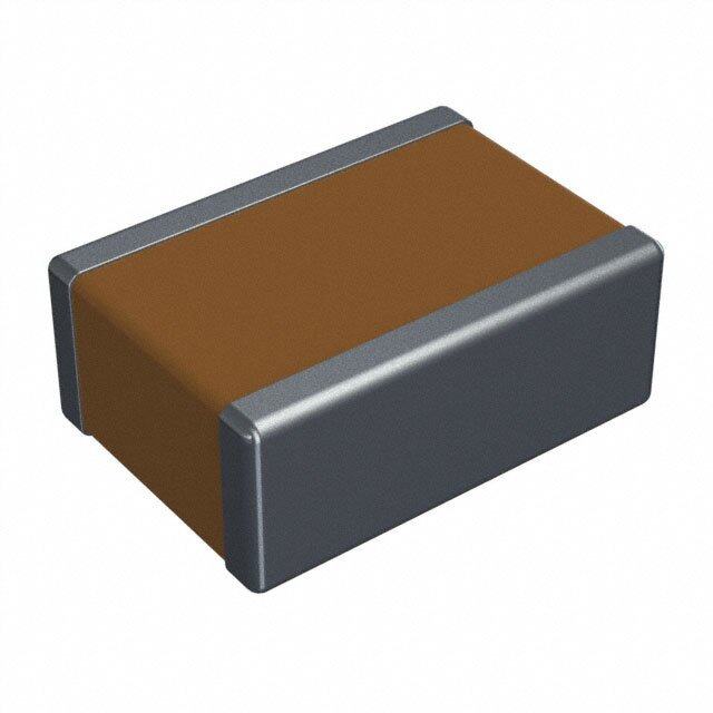
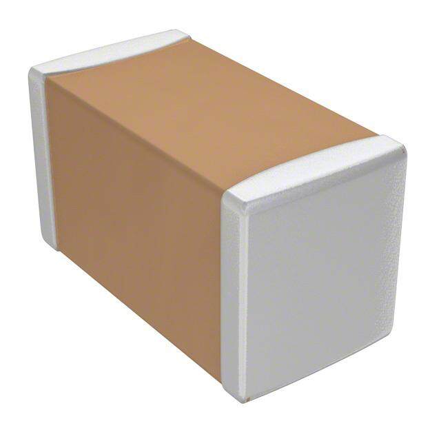
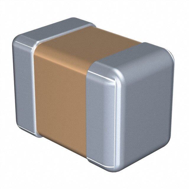
ICGOO电子元器件商城为您提供VJ0603A470JXAAC由Vishay设计生产,在icgoo商城现货销售,并且可以通过原厂、代理商等渠道进行代购。 VJ0603A470JXAAC价格参考¥1.55-¥1.55。VishayVJ0603A470JXAAC封装/规格:陶瓷电容器, 47pF ±5% 50V 陶瓷电容器 C0G,NP0 0603(1608 公制)。您可以下载VJ0603A470JXAAC参考资料、Datasheet数据手册功能说明书,资料中有VJ0603A470JXAAC 详细功能的应用电路图电压和使用方法及教程。
Vishay Vitramon品牌的陶瓷电容器型号VJ0603A470JXAAC是一款高性能的多层陶瓷电容器(MLCC),其主要应用场景包括以下领域:

1. 电源管理:该电容器适用于DC-DC转换器、开关电源和LDO稳压器等电源管理电路中,用于滤波、去耦和储能。其低ESR和高频率特性使其在高频电源应用中表现出色。

2. 通信设备:广泛应用于基站、路由器、交换机等通信设备中,用于信号处理、滤波和匹配网络。其小型化设计(0603尺寸)和高可靠性满足了现代通信设备对空间和性能的要求。

3. 消费电子:适用于智能手机、平板电脑、笔记本电脑和其他便携式设备中的高频电路。其稳定性和抗干扰能力有助于提高设备的信号完整性和稳定性。

4. 工业控制:在工业自动化系统中,如PLC、变频器和伺服驱动器中,用于电源滤波和信号调理。其耐高温和高湿度的特性确保了在严苛环境下的可靠运行。

5. 汽车电子:可用于车载信息娱乐系统、传感器模块和动力管理系统中。其符合AEC-Q200标准,适合汽车级应用,提供卓越的温度稳定性和长期可靠性。

6. 射频和微波电路:在射频前端模块、滤波器和振荡器中,该电容器能够提供稳定的电容值和低插入损耗,支持高频信号传输。

总结来说,VJ0603A470JXAAC凭借其小型化、高可靠性和宽温度范围的特点,适用于各种需要高性能陶瓷电容器的场景,尤其是在高频、高密度和高可靠性要求的应用中表现优异。
| 参数 | 数值 |
| 产品目录 | |
| 描述 | CAP CER 47PF 50V 5% NP0 0603多层陶瓷电容器MLCC - SMD/SMT 47pF 50volts C0G 5% |
| 产品分类 | |
| 品牌 | Vishay / VitramonVishay Vitramon |
| 产品手册 | http://www.vishay.com/doc?45200 |
| 产品图片 |
|
| rohs | 过渡期间无铅 / 符合限制有害物质指令(RoHS)规范要求 |
| 产品系列 | MLCC,多层陶瓷电容器MLCC - SMD/SMT,Vishay / Vitramon VJ0603A470JXAACVJ |
| 数据手册 | |
| 产品型号 | VJ0603A470JXAACVJ0603A470JXAAC |
| 产品 | General Type MLCCs |
| 产品种类 | 多层陶瓷电容器MLCC - SMD/SMT |
| 其它名称 | 720-1371-1 |
| 包装 | 剪切带 (CT) |
| 厚度(最大值) | 0.036"(0.92mm) |
| 商标 | Vishay / Vitramon |
| 外壳代码-in | 0603 |
| 外壳代码-mm | 1608 |
| 外壳宽度 | 0.8 mm |
| 外壳长度 | 1.6 mm |
| 外壳高度 | 0.92 mm |
| 大小/尺寸 | 0.063" 长 x 0.031" 宽(1.60mm x 0.80mm) |
| 安装类型 | 表面贴装,MLCC |
| 容差 | ±5%5 % |
| 封装 | Reel |
| 封装/外壳 | 0603(1608 公制) |
| 封装/箱体 | 0603 (1608 metric) |
| 工作温度 | -55°C ~ 125°C |
| 工作温度范围 | - 55 C to + 150 C |
| 工厂包装数量 | 4000 |
| 应用 | 通用 |
| 引线形式 | - |
| 引线间距 | - |
| 损耗因数DF | 0.1 |
| 最大工作温度 | + 150 C |
| 最小工作温度 | - 55 C |
| 标准包装 | 1 |
| 温度系数 | C0G,NP0 |
| 温度系数/代码 | +/- 30 PPM / C |
| 特性 | - |
| 电介质 | C0G (NP0) |
| 电压-额定 | 50V |
| 电压额定值 | 50 V |
| 电压额定值AC | - |
| 电压额定值DC | 50 V |
| 电容 | 47 pF47pF |
| 端接类型 | SMD/SMT |
| 等级 | - |
| 类型 | Commercial SMD MLCCs |
| 系列 | VJ COMM |
| 高度-安装(最大值) | - |


- 商务部:美国ITC正式对集成电路等产品启动337调查
- 曝三星4nm工艺存在良率问题 高通将骁龙8 Gen1或转产台积电
- 太阳诱电将投资9.5亿元在常州建新厂生产MLCC 预计2023年完工
- 英特尔发布欧洲新工厂建设计划 深化IDM 2.0 战略
- 台积电先进制程称霸业界 有大客户加持明年业绩稳了
- 达到5530亿美元!SIA预计今年全球半导体销售额将创下新高
- 英特尔拟将自动驾驶子公司Mobileye上市 估值或超500亿美元
- 三星加码芯片和SET,合并消费电子和移动部门,撤换高东真等 CEO
- 三星电子宣布重大人事变动 还合并消费电子和移动部门
- 海关总署:前11个月进口集成电路产品价值2.52万亿元 增长14.8%


PDF Datasheet 数据手册内容提取
VJ Commercial Series www.vishay.com Vishay Vitramon Surface Mount Multilayer Ceramic Chip Capacitors for Commercial Applications FEATURES • C0G (NP0) and X7R dielectrics offered • C0G (NP0) is an ultra-stable dielectric offering a very low Temperature Coefficient of Capacitance (TCC) • C0G (NP0) offers low dissipation • Excellent aging characteristics • Ideal for decoupling and filtering (X7R) • Ideal for surge suppression and high voltage Available applications • Wide range of case sizes, voltage ratings and capacitance values • Wet build process • Reliable Noble Metal Electrode (NME) system • Material categorization: for definitions of complianc e please see www.vishay.com/doc?99912 APPLICATIONS • Timing and tuning circuits • Sensor and scanner applications • Decoupling and filtering • Surge suppression ELECTRICAL SPECIFICATIONS C0G (NP0) DIELECTRIC X7R DIELECTRIC GENERAL SPECIFICATION GENERAL SPECIFICATION Note Note Electrical characteristics at +25 °C unless otherwise specified Electrical characteristics at +25 °C unless otherwise specified Operating Temperature: -55 °C to +150 °C Operating Temperature: -55 °C to +150 °C (above +125 °C changed characteristics) (above +125 °C changed characteristics) Capacitance Range: 1 pF to 56 nF Capacitance Range: 120 pF to 6.8 μF Voltage Range: 25 V to 1000 V Voltage Range: 16 V to 1000 V DC DC DC DC Temperature Coefficient of Capacitance (TCC): Temperature Coefficient of Capacitance (TCC): 0 ppm/°C ± 30 ppm/°C from -55 °C to +125 °C ± 15 % from -55 °C to +125 °C, with 0 V applied DC Dissipation Factor (DF): Dissipation Factor (DF): 0.1 % maximum at 1.0 V and 16 V / 25 V ratings: 3.5 % maximum at 1.0 V and 1 kHz RMS RMS 1 MHz for values 1000 pF > 25 V ratings: 2.5 % maximum at 1.0 V and 1 kHz RMS 0.1 % maximum at 1.0 V and RMS 1 kHz for values > 1000 pF Insulating Resistance: at +25 °C 100 000 M min. or 1000 F whichever is less Insulating Resistance: at +125 °C 10 000 M min. or 100 F whichever is less at +25 °C 100 000 M min. or 1000 F whichever is less at +125 °C 10 000 M min. or 100 F whichever is less Aging Rate: 1 % maximum per decade Aging Rate: 0 % maximum per decade Dielectric Strength Test: performed per method 103 of EIA 198-2-E. Dielectric Strength Test: Applied test voltages performed per method 103 of EIA 198-2-E. 250 V -rated: 250 % of rated voltage DC Applied test voltages 500 V -rated: min. 150 % of rated voltage DC 200 VDC-rated: 250 % of rated voltage 630 VDC, 1000 VDC-rated: min. 120 % of rated voltage 500 VDC-rated: 200 % of rated voltage 630 VDC,1000 VDC-rated: 150 % of rated voltage Revision: 10-Apr-2019 1 Document Number: 45199 For technical questions, contact: mlcc@vishay.com THIS DOCUMENT IS SUBJECT TO CHANGE WITHOUT NOTICE. THE PRODUCTS DESCRIBED HEREIN AND THIS DOCUMENT ARE SUBJECT TO SPECIFIC DISCLAIMERS, SET FORTH AT www.vishay.com/doc?91000
VJ Commercial Series www.vishay.com Vishay Vitramon QUICK REFERENCE DATA CAPACITANCE MAXIMUM VOLTAGE DIELECTRIC CASE (V) MINIMUM MAXIMUM 0402 100 1.0 pF 220 pF 0603 250 1.0 pF 1.0 nF 0805 500 1.0 pF 4.7 nF 1206 630 1.0 pF 10 nF 1210 630 56 pF 12 nF C0G (NP0) 1808 1000 27 pF 10 nF 1812 1000 39 pF 22 nF 1825 500 100 pF 39 nF 2220 1000 270 pF 47 nF 2225 1000 270 pF 56 nF 0402 100 120 pF 47 nF 0603 200 330 pF 150 nF 0805 250 330 pF 470 nF 1206 630 330 pF 1.0 μF 1210 630 390 pF 1.0 μF X7R 1808 1000 470 pF 270 nF 1812 1000 1.0 nF 1.0 μF 1825 1000 10 nF 2.7 μF 2220 500 15 nF 2.2 μF 2225 1000 33 nF 4.7 μF 3640 500 27 nF 6.8 μF Note • Detail ratings see “Selection Chart” Revision: 10-Apr-2019 2 Document Number: 45199 For technical questions, contact: mlcc@vishay.com THIS DOCUMENT IS SUBJECT TO CHANGE WITHOUT NOTICE. THE PRODUCTS DESCRIBED HEREIN AND THIS DOCUMENT ARE SUBJECT TO SPECIFIC DISCLAIMERS, SET FORTH AT www.vishay.com/doc?91000
VJ Commercial Series www.vishay.com Vishay Vitramon ORDERING INFORMATION VJ0805 (1) Y 102 K X A A T ### (3)(6) CASE DIELECTRIC CAPACITANCE CAPACITANCE TERMINATION DC MARKING PACKAGING PROCESS CODE NOMINAL CODE TOLERANCE VOLTAGE CODE RATING (2) 0402 A = C0G Expressed in B = ± 0.10 pF X = Ni barrier J = 16 V A = C = 7" reel / paper tape 0603 (NP0) picofarads (pF). C = ± 0.25 pF 100 % tin plated X = 25 V unmarked T = 7" reel / plastic tape 0805 Y = X7R The first two D = ± 0.5 pF matte finish A = 50 V M = marked P = 11 1/4" / 13" reel / 1206 digits are F = ± 1 % F, E = AgPd (4) B = 100 V Note paper tape 1210 significant, the G = ± 2 % B = polymer C = 200 V Marking R = 11 1/4" / 13" reel / 1808 third is a J = ± 5 % 100 % tin plated P = 250 V is only plastic tape 1812 multiplier. K = ± 10 % matte finish (5) E = 500 V available for O = 7" reel / 1825 Examples: M = ± 20 % L = 630 V 0805 and flamed paper tape 2220 1R8 = 1.8 pF Note G = 1000 V 1206 with I = 11 1/4" / 13"reel / 2225 102 = 1000 pF C0G (NP0): termination flamed paper tape 3640 B, C, D < 10 pF code “X” / Note F, G, J, K 10 pF “B” “I” and “O” are used for X7R: “F”, “E” termination J, K, M size 0402 / 0603 / 0805 Notes (1) Case size designator may be replaced by four digit drawing number used to control non-standard products and / or special requirements (2) DC voltage rating should not be exceeded in application. Other application factors may affect the MLCC performance. Consult for questions: mlcc@vishay.com (3) Process code may be added with up to three digits, used to control non-standard products and / or special requirements (4) Termination code “E” is for conductive epoxy assembly (5) Polymer termination for size 0603 and larger. Packaging only in plastic tape “T” / “R” (6) Variable plastic / paper tape, see ratings in “Selection Charts” ENVIRONMENTAL STATUS TERMINATION CODE TERMINATION DESCRIPTION RoHS COMPLIANT VISHAY GREEN X Ni barrier 100 % tin plated matte finish Yes Yes E AgPd Yes Yes B Polymer layer, 100 % tin plated matte finish Yes No F AgPd Yes No Revision: 10-Apr-2019 3 Document Number: 45199 For technical questions, contact: mlcc@vishay.com THIS DOCUMENT IS SUBJECT TO CHANGE WITHOUT NOTICE. THE PRODUCTS DESCRIBED HEREIN AND THIS DOCUMENT ARE SUBJECT TO SPECIFIC DISCLAIMERS, SET FORTH AT www.vishay.com/doc?91000
VJ Commercial Series www.vishay.com Vishay Vitramon DIMENSIONS in inches (millimeters) L W T MAX. P TERMINATION MAXIMUM LENGTH WIDTH (P) CASE CODE STYLE THICKNESS (L) (W) (T) MINIMUM MAXIMUM 0.040 + 0.004 / - 0.002 0.020 + 0.004 / - 0.002 0.024 0.004 0.016 0402 VJ0402 (1.00 + 0.10 / - 0.05) (0.50 + 0.10 / - 0.05) (0.60) (0.10) (0.41) 0.063 ± 0.006 0.031 ± 0.006 0.038 0.012 0.022 0603 VJ0603 (1.60 ± 0.15) (0.80 ± 0.15) (0.97) (0.30) (0.55) 0.079 ± 0.008 0.049 ± 0.008 0.057 0.010 0.030 0805 VJ0805 (2.00 ± 0.20) (1.25 ± 0.20) (1.45) (0.25) (0.76) 0.126 ± 0.010 0.063 ± 0.010 0.067 0.010 0.030 1206 VJ1206 (3.20 ± 0.25) (1.60 ± 0.25) (1.70) (0.25) (0.76) 0.126 ± 0.010 0.098 ± 0.010 0.067 0.010 0.030 1210 VJ1210 (3.20 ± 0.25) (2.50 ± 0.25) (1.70) (0.25) (0.76) 0.180 ± 0.012 0.080 ± 0.010 0.086 0.010 0.035 1808 VJ1808 (4.57 ± 0.30) (2.03 ± 0.25) (2.18) (0.25) (0.90) 0.177 ± 0.012 0.126 ± 0.008 0.086 0.010 0.035 1812 VJ1812 (4.50 ± 0.30) (3.20 ± 0.20) (2.18) (0.25) (0.90) 0.177 ± 0.012 0.252 ± 0.010 0.086 0.010 0.035 1825 VJ1825 (4.50 ± 0.30) (6.40 ± 0.25) (2.18) (0.25) (0.90) 0.220 ± 0.010 0.200 ± 0.010 0.086 0.010 0.037 2220 VJ2220 (5.59 ± 0.25) (5.08 ± 0.25) (2.18) (0.25) (0.95) 0.220 ± 0.010 0.250 ± 0.010 0.086 0.010 0.037 2225 VJ2225 (5.59 ± 0.25) (6.35 ± 0.25) (2.18) (0.25) (0.95) 0.360 ± 0.015 0.400 ± 0.015 0.086 0.010 0.039 3640 VJ3640 (9.14 ± 0.38) (10.20 ± 0.38) (2.18) (0.25) (1.00) Note • Polymer (B-termination) have increased dimensions: length 0.006"(0.15 mm) Revision: 10-Apr-2019 4 Document Number: 45199 For technical questions, contact: mlcc@vishay.com THIS DOCUMENT IS SUBJECT TO CHANGE WITHOUT NOTICE. THE PRODUCTS DESCRIBED HEREIN AND THIS DOCUMENT ARE SUBJECT TO SPECIFIC DISCLAIMERS, SET FORTH AT www.vishay.com/doc?91000
VJ Commercial Series www.vishay.com Vishay Vitramon SELECTION CHART DIELECTRIC C0G (NP0) STYLE VJ0402 VJ0603 VJ0805 VJ1206 (1) VJ1210 (1) CASE CODE 0402 0603 0805 1206 1210 VOLTAGE (V ) 25 50 100 50 100 200 250 50 100 200 500 50 100 200 500 630 50 100 200 500 630 DC VOLTAGE CODE X A B A B C P A B C E A B C E L A B C E L CAP. CODE CAP. 1R0 1.0 pF •• •• •• •• •• •• •• •• •• •• •• •• •• •• •• •• 1R2 1.2 pF •• •• •• •• •• •• •• •• •• •• •• •• •• •• •• •• 1R5 1.5 pF •• •• •• •• •• •• •• •• •• •• •• •• •• •• •• •• 1R8 1.8 pF •• •• •• •• •• •• •• •• •• •• •• •• •• •• •• •• 2R2 2.2 pF •• •• •• •• •• •• •• •• •• •• •• •• •• •• •• •• 2R7 2.7 pF •• •• •• •• •• •• •• •• •• •• •• •• •• •• •• •• 3R3 3.3 pF •• •• •• •• •• •• •• •• •• •• •• •• •• •• •• •• 3R9 3.9 pF •• •• •• •• •• •• •• •• •• •• •• •• •• •• •• •• 4R7 4.7 pF •• •• •• •• •• •• •• •• •• •• •• •• •• •• •• •• 5R6 5.6 pF •• •• •• •• •• •• •• •• •• •• •• •• •• •• •• •• 6R8 6.8 pF •• •• •• •• •• •• •• •• •• •• •• •• •• •• •• •• 8R2 8.2 pF •• •• •• •• •• •• •• •• •• •• •• •• •• •• •• •• 100 10 pF •• •• •• •• •• •• •• •• •• •• •• •• •• •• •• •• 120 12 pF •• •• •• •• •• •• •• •• •• •• •• •• •• •• •• •• 150 15 pF •• •• •• •• •• •• •• •• •• •• •• •• •• •• •• •• 180 18 pF •• •• •• •• •• •• •• •• •• •• •• •• •• •• •• •• 220 22 pF •• •• •• •• •• •• •• •• •• •• •• •• •• •• •• •• 270 27 pF •• •• •• •• •• •• •• •• •• •• •• •• •• •• •• 330 33 pF •• •• •• •• •• •• •• •• •• •• •• •• •• •• •• 390 39 pF •• •• •• •• •• •• •• •• •• •• •• •• •• •• •• 470 47 pF •• •• •• •• •• •• •• •• •• •• •• •• •• •• •• 560 56 pF •• •• •• •• •• •• •• •• •• •• •• •• •• •• •• • • 680 68 pF •• •• •• •• •• •• •• •• •• •• •• •• •• •• •• • • 820 82 pF •• •• •• •• •• •• •• •• •• •• •• •• •• •• •• • • 101 100 pF •• •• •• •• •• •• •• •• •• •• • • • • • • • 121 120 pF •• •• •• •• •• •• •• •• •• •• • • • • • • • • • • 151 150 pF •• •• •• •• •• •• •• •• •• • • • • • • • • • • 181 180 pF •• •• •• •• • •• •• •• •• • • • • • • • • • • 221 220 pF •• •• •• •• • •• •• •• • • • • • • • • • • • 271 270 pF •• •• • •• •• •• • • • • • • • • • • • 331 330 pF •• •• •• •• •• • • • • • • • • • • • 391 390 pF •• •• •• •• •• • • • • • • • • • • • 471 470 pF •• •• •• • • • • • • • • • • • • 561 560 pF •• •• •• • • • • • • • • • • • 681 680 pF •• •• •• • • • • • • • • • • • 821 820 pF •• •• •• • • • • • • • • • • • 102 1.0 nF •• •• •• • • • • • • • • • • • 122 1.2 nF •• • • • • • • • • • 152 1.5 nF •• • • • • • • • • • 182 1.8 nF • • • • • • • • • 222 2.2 nF • • • • • • • 272 2.7 nF • • • • • • • 332 3.3 nF • • • • • • • 392 3.9 nF • • • • • • 472 4.7 nF • • • • • • 562 5.6 nF • • • • • 682 6.8 nF • • • • • 822 8.2 nF • • • • • 103 10 nF • • • • 123 12 nF • • 153 15 nF 183 18 nF 223 22 nF 273 27 nF 333 33 nF 393 39 nF 473 47 nF 563 56 nF Notes RoHS-compliant •• Paper tape • Plastic tape (1) See soldering recommendations within this data book, or visit www.vishay.com/doc?45034 Revision: 10-Apr-2019 5 Document Number: 45199 For technical questions, contact: mlcc@vishay.com THIS DOCUMENT IS SUBJECT TO CHANGE WITHOUT NOTICE. THE PRODUCTS DESCRIBED HEREIN AND THIS DOCUMENT ARE SUBJECT TO SPECIFIC DISCLAIMERS, SET FORTH AT www.vishay.com/doc?91000
VJ Commercial Series www.vishay.com Vishay Vitramon SELECTION CHART DIELECTRIC C0G (NP0) STYLE VJ1808 (1) VJ1812 (1) VJ1825 (1) CASE CODE 1808 1812 1825 VOLTAGE (V ) 50 100 200 500 1000 50 100 200 500 1000 50 100 200 500 DC VOLTAGE CODE A B C E G A B C E G A B C E CAP. CODE CAP. 1R0 1.0 pF 1R2 1.2 pF 1R5 1.5 pF 1R8 1.8 pF 2R2 2.2 pF 2R7 2.7 pF 3R3 3.3 pF 3R9 3.9 pF 4R7 4.7 pF 5R6 5.6 pF 6R8 6.8 pF 8R2 8.2 pF 100 10 pF 120 12 pF 150 15 pF 180 18 pF 220 22 pF 270 27 pF • • 330 33 pF • • 390 39 pF • • • • • • • 470 47 pF • • • • • • • 560 56 pF • • • • • • • 680 68 pF • • • • • • • 820 82 pF • • • • • • • 101 100 pF • • • • • • • • 121 120 pF • • • • • • • • • 151 150 pF • • • • • • • • • 181 180 pF • • • • • • • • • 221 220 pF • • • • • • • • • • • 271 270 pF • • • • • • • • • • • 331 330 pF • • • • • • • • • • • 391 390 pF • • • • • • • • • • • 471 470 pF • • • • • • • • • • • 561 560 pF • • • • • • • • • • • 681 680 pF • • • • • • • • • • • 821 820 pF • • • • • • • • • • • 102 1.0 nF • • • • • • • • • • • • • • 122 1.2 nF • • • • • • • • • • • • • 152 1.5 nF • • • • • • • • • • • • • 182 1.8 nF • • • • • • • • • • • • • 222 2.2 nF • • • • • • • • • • • • 272 2.7 nF • • • • • • • • • • • 332 3.3 nF • • • • • • • • • • • 392 3.9 nF • • • • • • • • • • • 472 4.7 nF • • • • • • • • • • • 562 5.6 nF • • • • • • • • • • • 682 6.8 nF • • • • • • • • • • • 822 8.2 nF • • • • • • • • • • 103 10 nF • • • • • • • • • 123 12 nF • • • • • • 153 15 nF • • • • • 183 18 nF • • • • 223 22 nF • • • • 273 27 nF • • • 333 33 nF • • 393 39 nF • 473 47 nF 563 56 nF Notes RoHS-compliant • Plastic tape (1) See soldering recommendations within this data book, or visit www.vishay.com/doc?45034 Revision: 10-Apr-2019 6 Document Number: 45199 For technical questions, contact: mlcc@vishay.com THIS DOCUMENT IS SUBJECT TO CHANGE WITHOUT NOTICE. THE PRODUCTS DESCRIBED HEREIN AND THIS DOCUMENT ARE SUBJECT TO SPECIFIC DISCLAIMERS, SET FORTH AT www.vishay.com/doc?91000
VJ Commercial Series www.vishay.com Vishay Vitramon SELECTION CHART DIELECTRIC C0G (NP0) STYLE VJ2220 (1) VJ2225 (1) CASE CODE 2220 2225 VOLTAGE (V ) 50 100 200 500 630 1000 50 100 200 500 1000 DC VOLTAGE CODE A B C E L G A B C E G CAP. CODE CAP. 1R0 1.0 pF 1R2 1.2 pF 1R5 1.5 pF 1R8 1.8 pF 2R2 2.2 pF 2R7 2.7 pF 3R3 3.3 pF 3R9 3.9 pF 4R7 4.7 pF 5R6 5.6 pF 6R8 6.8 pF 8R2 8.2 pF 100 10 pF 120 12 pF 150 15 pF 180 18 pF 220 22 pF 270 27 pF 330 33 pF 390 39 pF 470 47 pF 560 56 pF 680 68 pF 820 82 pF 101 100 pF 121 120 pF 151 150 pF 181 180 pF 221 220 pF 271 270 pF • • • • • • • 331 330 pF • • • • • • • 391 390 pF • • • • • • • 471 470 pF • • • • • • • • 561 560 pF • • • • • • • • 681 680 pF • • • • • • • • 821 820 pF • • • • • • • • 102 1.0 nF • • • • • • • • • 122 1.2 nF • • • • • • • • • • • 152 1.5 nF • • • • • • • • • • • 182 1.8 nF • • • • • • • • • • • 222 2.2 nF • • • • • • • • • • • 272 2.7 nF • • • • • • • • • • • 332 3.3 nF • • • • • • • • • • • 392 3.9 nF • • • • • • • • • • • 472 4.7 nF • • • • • • • • • • 562 5.6 nF • • • • • • • • • 682 6.8 nF • • • • • • • 822 8.2 nF • • • • • • • 103 10 nF • • • • • • • 123 12 nF • • • • • • • 153 15 nF • • • • • • 183 18 nF • • • • • 223 22 nF • • • • • 273 27 nF • • • • • 333 33 nF • • • • • 393 39 nF • • • • 473 47 nF • • • 563 56 nF • Notes RoHS-compliant • Plastic tape (1) See soldering recommendations within this data book, or visit www.vishay.com/doc?45034 Revision: 10-Apr-2019 7 Document Number: 45199 For technical questions, contact: mlcc@vishay.com THIS DOCUMENT IS SUBJECT TO CHANGE WITHOUT NOTICE. THE PRODUCTS DESCRIBED HEREIN AND THIS DOCUMENT ARE SUBJECT TO SPECIFIC DISCLAIMERS, SET FORTH AT www.vishay.com/doc?91000
VJ Commercial Series www.vishay.com Vishay Vitramon SELECTION CHART DIELECTRIC X7R STYLE VJ0402 VJ0603 VJ0805 CASE CODE 0402 0603 0805 VOLTAGE (V ) 16 25 50 100 16 25 50 100 200 16 25 50 100 200 250 DC VOLTAGE CODE J X A B J X A B C J X A B C P CAP. CODE CAP. 121 120 pF •• •• •• •• 151 150 pF •• •• •• •• 181 180 pF •• •• •• •• 221 220 pF •• •• •• •• 271 270 pF •• •• •• •• 331 330 pF •• •• •• •• •• •• •• •• 391 390 pF •• •• •• •• •• •• •• •• •• •• 471 470 pF •• •• •• •• •• •• •• •• •• •• •• •• •• •• 561 560 pF •• •• •• •• •• •• •• •• •• •• •• •• •• •• 681 680 pF •• •• •• •• •• •• •• •• •• •• •• •• •• •• 821 820 pF •• •• •• •• •• •• •• •• •• •• •• •• •• •• 102 1.0 nF •• •• •• •• •• •• •• •• •• •• •• •• •• •• •• 122 1.2 nF •• •• •• •• •• •• •• •• •• •• •• •• •• •• •• 152 1.5 nF •• •• •• •• •• •• •• •• •• •• •• •• •• •• •• 182 1.8 nF •• •• •• •• •• •• •• •• •• •• •• •• •• •• •• 222 2.2 nF •• •• •• •• •• •• •• •• •• •• •• •• •• •• •• 272 2.7 nF •• •• •• •• •• •• •• •• •• •• •• •• •• •• •• 332 3.3 nF •• •• •• •• •• •• •• •• •• •• •• •• •• •• •• 392 3.9 nF •• •• •• •• •• •• •• •• •• •• •• •• •• •• •• 472 4.7 nF •• •• •• •• •• •• •• •• •• •• •• •• •• •• •• 562 5.6 nF •• •• •• •• •• •• •• •• •• •• •• •• •• 682 6.8 nF •• •• •• •• •• •• •• •• •• •• •• •• •• 822 8.2 nF •• •• •• •• •• •• •• •• •• •• •• •• •• 103 10 nF •• •• •• •• •• •• •• •• •• •• •• •• • 123 12 nF •• •• •• •• •• •• •• •• •• •• •• • 153 15 nF •• •• •• •• •• •• •• •• •• •• • • 183 18 nF •• •• •• •• •• •• •• •• •• •• • • 223 22 nF •• •• •• •• •• •• •• •• •• • • 273 27 nF •• •• •• •• •• •• •• •• •• • 333 33 nF •• •• •• •• •• •• •• •• • 393 39 nF •• •• •• •• •• •• •• •• • 473 47 nF •• •• •• •• •• •• •• • 563 56 nF •• •• •• •• •• •• • 683 68 nF •• •• •• •• •• • • 823 82 nF •• •• •• • • • • 104 100 nF •• •• •• • • • • 124 120 nF •• • • • 154 150 nF •• • • • 184 180 nF • • 224 220 nF • • 274 270 nF • • 334 330 nF • • 394 390 nF • 474 470 nF • 564 560 nF 684 680 nF 824 820 nF 105 1.0 μF 125 1.2 μF 155 1.5 μF 185 1.8 μF 225 2.2 μF 275 2.7 μF 335 3.3 μF 395 3.9 μF 475 4.7 μF 565 5.6 μF 685 6.8 μF Notes RoHS-compliant •• Paper tape • Plastic tape ••• Variable plastic / paper tape Revision: 10-Apr-2019 8 Document Number: 45199 For technical questions, contact: mlcc@vishay.com THIS DOCUMENT IS SUBJECT TO CHANGE WITHOUT NOTICE. THE PRODUCTS DESCRIBED HEREIN AND THIS DOCUMENT ARE SUBJECT TO SPECIFIC DISCLAIMERS, SET FORTH AT www.vishay.com/doc?91000
VJ Commercial Series www.vishay.com Vishay Vitramon SELECTION CHART DIELECTRIC X7R STYLE VJ1206 (1) VJ1210 (1) CASE CODE 1206 1210 VOLTAGE (V ) 16 25 50 100 200 250 500 630 16 25 50 100 200 250 500 630 DC VOLTAGE CODE J X A B C P E L J X A B C P E L CAP. CODE CAP. 121 120 pF 151 150 pF 181 180 pF 221 220 pF 271 270 pF 331 330 pF •• •• 391 390 pF •• •• • 471 470 pF •• •• •• •• •• •• • 561 560 pF •• •• •• •• •• •• • 681 680 pF •• •• •• •• •• •• • 821 820 pF •• •• •• •• •• •• • 102 1.0 nF •• •• •• •• •• •• •• • • 122 1.2 nF •• •• •• •• •• •• •• • • 152 1.5 nF •• •• •• •• •• •• •• • • 182 1.8 nF •• •• •• •• •• •• •• • • 222 2.2 nF •• •• •• •• •• •• •• • • 272 2.7 nF •• •• •• •• •• •• •• • • 332 3.3 nF •• •• •• •• •• •• •• • • • 392 3.9 nF •• •• •• •• •• •• •• • • • 472 4.7 nF •• •• •• •• •• •• •• • • • 562 5.6 nF •• •• •• •• •• • • • • • 682 6.8 nF •• •• •• •• •• • • • • • 822 8.2 nF •• •• •• •• •• • • • • • 103 10 nF •• •• •• •• •• • • • • • • • • • • 123 12 nF •• •• •• •• •• • • • • • • • • • • 153 15 nF •• •• •• •• •• • • • • • • • • • • 183 18 nF •• •• •• •• •• • • • • • • • • • • 223 22 nF •• •• •• •• •• • • • • • • • • 273 27 nF •• •• •• •• •• • • • • • • • • 333 33 nF •• •• •• •• •• • • • • • • • • • 393 39 nF •• •• •• •• • • • • • • • • • • 473 47 nF •• •• •• •• • • • • • • • • • • 563 56 nF •• •• •• •• • • • • • • • • 683 68 nF •• •• •• •• • • • • • • • • 823 82 nF •• •• • • • • • • • • • • 104 100 nF •• •• • • • • • • • • • • 124 120 nF •• •• • • • • • • • 154 150 nF •• •• • • • • • • • 184 180 nF •• •• • • • • • • • 224 220 nF • • • • • • • • 274 270 nF • • • • • • • • 334 330 nF • • • • • • • 394 390 nF • • • • • • • 474 470 nF • • • • • • • 564 560 nF • • • • • 684 680 nF • • • • • 824 820 nF • • • • • 105 1.0 μF • • • • • 125 1.2 μF 155 1.5 μF 185 1.8 μF 225 2.2 μF 275 2.7 μF 335 3.3 μF 395 3.9 μF 475 4.7 μF 565 5.6 μF 685 6.8 μF Notes RoHS-compliant •• Paper tape • Plastic tape (1) See soldering recommendations within this data book, or visit www.vishay.com/doc?45034 Revision: 10-Apr-2019 9 Document Number: 45199 For technical questions, contact: mlcc@vishay.com THIS DOCUMENT IS SUBJECT TO CHANGE WITHOUT NOTICE. THE PRODUCTS DESCRIBED HEREIN AND THIS DOCUMENT ARE SUBJECT TO SPECIFIC DISCLAIMERS, SET FORTH AT www.vishay.com/doc?91000
VJ Commercial Series www.vishay.com Vishay Vitramon SELECTION CHART DIELECTRIC X7R STYLE VJ1808 (1) VJ1812 (1) VJ1825 (1) CASE CODE 1808 1812 1825 VOLTAGE (V ) 50 100 200 500 1000 25 50 100 200 250 500 630 1000 25 50 100 200 250 500 1000 DC VOLTAGE CODE A B C E G X A B C P E L G X A B C P E G CAP. CODE CAP. 121 120 pF 151 150 pF 181 180 pF 221 220 pF 271 270 pF 331 330 pF 391 390 pF 471 470 pF • 561 560 pF • 681 680 pF • 821 820 pF • 102 1.0 nF • • • • • 122 1.2 nF • • • • • 152 1.5 nF • • • • • 182 1.8 nF • • • • • 222 2.2 nF • • • • • 272 2.7 nF • • • • • 332 3.3 nF • • • • • 392 3.9 nF • • • • • 472 4.7 nF • • • • • • 562 5.6 nF • • • • • • 682 6.8 nF • • • • • • 822 8.2 nF • • • • • • 103 10 nF • • • • • • • • • • • • • • • • 123 12 nF • • • • • • • • • • • • • • • 153 15 nF • • • • • • • • • • • • • • • 183 18 nF • • • • • • • • • • • • • • • 223 22 nF • • • • • • • • • • • • • • • • • • 273 27 nF • • • • • • • • • • • • • • • • • • 333 33 nF • • • • • • • • • • • • • • • • 393 39 nF • • • • • • • • • • • • • • • • 473 47 nF • • • • • • • • • • • • • • • • 563 56 nF • • • • • • • • • • • • • • • • 683 68 nF • • • • • • • • • • • • • • • 823 82 nF • • • • • • • • • • • • • • • 104 100 nF • • • • • • • • • • • • • • • • 124 120 nF • • • • • • • • • • • • • 154 150 nF • • • • • • • • • • • • • 184 180 nF • • • • • • • • • • • • • 224 220 nF • • • • • • • • • • • 274 270 nF • • • • • • • • • • • 334 330 nF • • • • • • • • • • 394 390 nF • • • • • • • • • 474 470 nF • • • • • • • • • 564 560 nF • • • • • • • • 684 680 nF • • • • • • • • 824 820 nF • • • • • • • • 105 1.0 μF • • • • • • • 125 1.2 μF • • • 155 1.5 μF • • • 185 1.8 μF • • 225 2.2 μF • 275 2.7 μF • 335 3.3 μF 395 3.9 μF 475 4.7 μF 565 5.6 μF 685 6.8 μF Notes RoHS-compliant • Plastic tape (1) See soldering recommendations within this data book, or visit www.vishay.com/doc?45034 Revision: 10-Apr-2019 10 Document Number: 45199 For technical questions, contact: mlcc@vishay.com THIS DOCUMENT IS SUBJECT TO CHANGE WITHOUT NOTICE. THE PRODUCTS DESCRIBED HEREIN AND THIS DOCUMENT ARE SUBJECT TO SPECIFIC DISCLAIMERS, SET FORTH AT www.vishay.com/doc?91000
VJ Commercial Series www.vishay.com Vishay Vitramon SELECTION CHART DIELECTRIC X7R STYLE VJ2220 (1) VJ2225 (1) VJ3640 (1) CASE CODE 2220 2225 3640 VOLTAGE (V ) 50 100 200 500 25 50 100 200 500 1000 25 50 100 200 500 DC VOLTAGE CODE A B C E X A B C E G X A B C E CAP. CODE CAP. 121 120 pF 151 150 pF 181 180 pF 221 220 pF 271 270 pF 331 330 pF 391 390 pF 471 470 pF 561 560 pF 681 680 pF 821 820 pF 102 1.0 nF 122 1.2 nF 152 1.5 nF 182 1.8 nF 222 2.2 nF 272 2.7 nF 332 3.3 nF 392 3.9 nF 472 4.7 nF 562 5.6 nF 682 6.8 nF 822 8.2 nF 103 10 nF 123 12 nF 153 15 nF • 183 18 nF • 223 22 nF • 273 27 nF • • • 333 33 nF • • • • • • • • • 393 39 nF • • • • • • • • • 473 47 nF • • • • • • • • • 563 56 nF • • • • • • • • • 683 68 nF • • • • • • • • • 823 82 nF • • • • • • • • • 104 100 nF • • • • • • • • • • 124 120 nF • • • • • • • • • 154 150 nF • • • • • • • • • 184 180 nF • • • • • • • • • • • • 224 220 nF • • • • • • • • • • • • • 274 270 nF • • • • • • • • • • • • • 334 330 nF • • • • • • • • • • • • • 394 390 nF • • • • • • • • • • • • 474 470 nF • • • • • • • • • • • • 564 560 nF • • • • • • • • • • • • 684 680 nF • • • • • • • • • • • • 824 820 nF • • • • • • • • • • • 105 1.0 μF • • • • • • • • • • • 125 1.2 μF • • • • • • • • • • 155 1.5 μF • • • • • • • • 185 1.8 μF • • • • • • • • 225 2.2 μF • • • • • • 275 2.7 μF • • • • • 335 3.3 μF • • • • 395 3.9 μF • • • • 475 4.7 μF • • • 565 5.6 μF • 685 6.8 μF • Notes RoHS-compliant • Plastic tape (1) See soldering recommendations within this data book, or visit www.vishay.com/doc?45034 Revision: 10-Apr-2019 11 Document Number: 45199 For technical questions, contact: mlcc@vishay.com THIS DOCUMENT IS SUBJECT TO CHANGE WITHOUT NOTICE. THE PRODUCTS DESCRIBED HEREIN AND THIS DOCUMENT ARE SUBJECT TO SPECIFIC DISCLAIMERS, SET FORTH AT www.vishay.com/doc?91000
VJ Commercial Series www.vishay.com Vishay Vitramon C0G (NP0) DIELECTRIC - TYPICAL PARAMETERS Temperature Coefficient of Capacitance Insulation Resistance vs. Temperature 2.0 10000 10 000 10000 1.5 %) 1.0 ΩF) e ( 1000 e ( 1000 1000 g 0.5 c n n 2nd lineance Cha -0.50 1st line2nd line 2nd linen Resista 1st line2nd line acit 100 atio 100 100 Cap -1.0 nsul I -1.5 -2.0 10 10 10 -75 -50 -25 0 25 50 75 100125150175 10 25 50 100 150 Temperature (°C) Temperature (°C) Aging Rate Voltage Coefficient of Capacitance 0.2 10000 0.2 10000 %) 0.1 %) 0.1 e ( 1000 e ( 1000 g g n n 2nd linence Cha 0 1st line2nd line 2nd linence Cha 0 1st line2nd line a a cit 100 cit 100 a a ap -0.1 ap -0.1 C C -0.2 10 -0.2 10 1 10 100 1000 10 000 0 10 20 30 40 50 60 70 80 90 100 Hours Applied DC Voltage (V ) DC Change of Capacitance with Frequency 2 10000 %) 1 e ( 1000 g n 2nd linence Cha 0 1st line2nd line a cit 100 a ap -1 C -2 10 1 10 100 1000 Frequency (kHz) Revision: 10-Apr-2019 12 Document Number: 45199 For technical questions, contact: mlcc@vishay.com THIS DOCUMENT IS SUBJECT TO CHANGE WITHOUT NOTICE. THE PRODUCTS DESCRIBED HEREIN AND THIS DOCUMENT ARE SUBJECT TO SPECIFIC DISCLAIMERS, SET FORTH AT www.vishay.com/doc?91000
VJ Commercial Series www.vishay.com Vishay Vitramon X7R DIELECTRIC - TYPICAL PARAMETERS Temperature Coefficient of Capacitance Insulation Resistance vs. Temperature 15 10000 10 000 10000 10 %) 5 ΩF) e ( 0 1000 e ( 1000 1000 g c n n 2nd lineance Cha -1-50 1st line2nd line 2nd linen Resista 1st line2nd line acit -15 100 atio 100 100 Cap -20 nsul I -25 -30 10 10 10 -75 -50 -25 0 25 50 75 100125150175 10 25 100 150 Temperature (°C) Temperature (°C) Dissipation Factor vs. Temperature Aging Rate 6.0 10000 1 10000 5.5 5.0 0 2nd lineation Factor (%) 23344.....50505 1000 1st line2nd line 2nd lineance Change (%) --21 1000 1st line2nd line Dissip 12..50 100 apacit 100 C -3 1.0 0.5 0 10 -4 10 -75 -50 -25 0 25 50 75 100125150175 1 10 100 1000 10 000 Temperature (°C) Hours Rated Voltage vs. Temperature Voltage Coefficient of Capacitance 10000 5 10000 200 0 %) %) 150 1000 e ( -5 1000 2nd lineed Voltage ( 100 1st line2nd line 2nd lineance Chang --1150 25 V rated 50 V rated 100 V rated 1st line2nd line Rat 100 pacit -20 100 50 Ca -25 0 10 -30 10 -75-50 -25 0 25 50 75 100125150175 0 10 20 30 40 50 60 70 80 90 100 Temperature (°C) Applied DC Voltage (V ) DC Revision: 10-Apr-2019 13 Document Number: 45199 For technical questions, contact: mlcc@vishay.com THIS DOCUMENT IS SUBJECT TO CHANGE WITHOUT NOTICE. THE PRODUCTS DESCRIBED HEREIN AND THIS DOCUMENT ARE SUBJECT TO SPECIFIC DISCLAIMERS, SET FORTH AT www.vishay.com/doc?91000
VJ Commercial Series www.vishay.com Vishay Vitramon X7R DIELECTRIC - TYPICAL PARAMETERS Dissipation Factor vs. Voltage Dissipation Factor vs. Voltage 0.020 10000 0.020 10000 0.016 0.016 or 1000 or 1000 ct ct 2nd linesipation Fa 0.012 100 V 1st line2nd line 2nd linesipation Fa 0.012 1st line2nd line s 100 s 100 Di Di 0.008 0.008 500 V / 630 V 50 V 200 V 0.004 10 0.004 10 0 10 20 30 40 50 60 70 80 90 100 0 100 200 300 400 500 600 700 Applied DC Voltage (V ) Applied DC Voltage (V ) DC DC STANDARD PACKAGING QUANTITIES (1)(2)(3) 7" REEL QUANTITIES 11 1/4" AND 13" REEL QUANTITIES CASE TAPE PAPER TAPE PLASTIC TAPE PAPER TAPE PLASTIC TAPE CODE SIZE PACKAGING CODE PACKAGING CODE PACKAGING CODE PACKAGING CODE “C” / “O” “T” “P” / “I” “R” 0402 8 mm 5000 n/a 10 000 n/a 0603 (4)(5)(6) 8 mm 4000 4000 10 000 10 000 0805 (4)(5) 8 mm 3000 3000 10 000 10 000 1206 (4)(5) 8 mm 3000 2500 / 3000 10 000 9000 / 10 000 1210 (4) 8 mm n/a 2000 / 2500 / 3000 n/a 9000 / 10 000 1808 12 mm n/a 2000 n/a 10 000 1812 12 mm n/a 1000 n/a 4000 1825 12 mm n/a 1000 n/a 4000 2220 12 mm n/a 1000 n/a n/a 2225 12 mm n/a 500 n/a n/a 3640 16 mm n/a 500 n/a n/a Notes (1) Vishay Vitramon uses embossed plastic carrier tape (2) REFERENCE: EIA standard RS 481 - “Taping of Surface Mount Components for Automatic Placement” (3) n/a = not available (4) Packaging “C” / “P” / “O” / “I” and “T” / “R” or lower quantities can depend from product thickness (5) Polymer termination, code “B”, only available in plastic tape “T” / “R” (6) Variable packaging codes, see ratings in “Selection Charts” STORAGE AND HANDLING CONDITIONS (1)Store the components at 5 °C to 40 °C ambient temperature and 70 % relative humidity conditions. (2)The product is recommended to be used within a time-frame of 2 years after shipment. Check solderability in case extended shelf life beyond the expiry date is needed. Precautions: a. Do not store products in an environment containing corrosive elements, especially where chloride gas, sulfide gas, acid, alkali, salt or the like are present. This may cause corrosion or oxidization of the terminations, which can easily lead to poor soldering. b. Store products on the shelf and avoid exposure to moisture or dust. c. Do not expose products to excessive shock, vibration, direct sunlight and so on. Revision: 10-Apr-2019 14 Document Number: 45199 For technical questions, contact: mlcc@vishay.com THIS DOCUMENT IS SUBJECT TO CHANGE WITHOUT NOTICE. THE PRODUCTS DESCRIBED HEREIN AND THIS DOCUMENT ARE SUBJECT TO SPECIFIC DISCLAIMERS, SET FORTH AT www.vishay.com/doc?91000
Legal Disclaimer Notice www.vishay.com Vishay Disclaimer ALL PRODUCT, PRODUCT SPECIFICATIONS AND DATA ARE SUBJECT TO CHANGE WITHOUT NOTICE TO IMPROV E RELIABILITY, FUNCTION OR DESIGN OR OTHERWISE. Vishay Intertechnology, Inc., its affiliates, agents, and employees, and all persons acting on its or their behalf (collectively, “Vishay”), disclaim any and all liability for any errors, inaccuracies or incompleteness contained in any datasheet or in any other disclosure relating to any product. Vishay makes no warranty, representation or guarantee regarding the suitability of the products for any particular purpose o r the continuing production of any product. To the maximum extent permitted by applicable law, Vishay disclaims (i) any and all liability arising out of the application or use of any product, (ii) any and all liability, including without limitation special, consequential or incidental damages, and (iii) any and all implied warranties, including warranties of fitness for particular purpose, non-infringement and merchantability. Statements regarding the suitability of products for certain types of applications are based on Vishay’s knowledge of typical requirements that are often placed on Vishay products in generic applications. Such statements are not binding statements about the suitability of products for a particular application. It is the customer’s responsibility to validate that a particular product with the properties described in the product specification is suitable for use in a particular application. Parameters provided in datasheets and / or specifications may vary in different applications and performance may vary over time. All operating parameters, including typical parameters, must be validated for each customer application by the customer’s technical experts. Product specifications do not expand or otherwise modify Vishay’s terms and conditions of purchase, including but not limited to the warranty expressed therein. Except as expressly indicated in writing, Vishay products are not designed for use in medical, life-saving, or life-sustainin g applications or for any other application in which the failure of the Vishay product could result in personal injury or death. Customers using or selling Vishay products not expressly indicated for use in such applications do so at their own risk . Please contact authorized Vishay personnel to obtain written terms and conditions regarding products designed for such applications. No license, express or implied, by estoppel or otherwise, to any intellectual property rights is granted by this documen t or by any conduct of Vishay. Product names and markings noted herein may be trademarks of their respective owners. © 2019 VISHAY INTERTECHNOLOGY, INC. ALL RIGHTS RESERVED Revision: 01-Jan-2019 1 Document Number: 91000