ICGOO在线商城 > 电路保护 > TVS - 变阻器,MOV > V150LS2P

 Datasheet下载
- 型号: V150LS2P
- 制造商: Littelfuse
- 库位|库存: xxxx|xxxx
- 要求:
| 数量阶梯 | 香港交货 | 国内含税 |
| +xxxx | $xxxx | ¥xxxx |
查看当月历史价格
查看今年历史价格
V150LS2P产品简介:
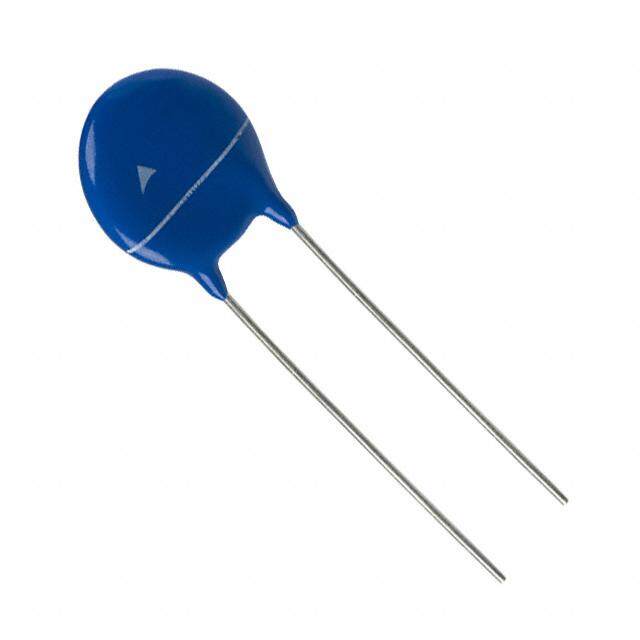
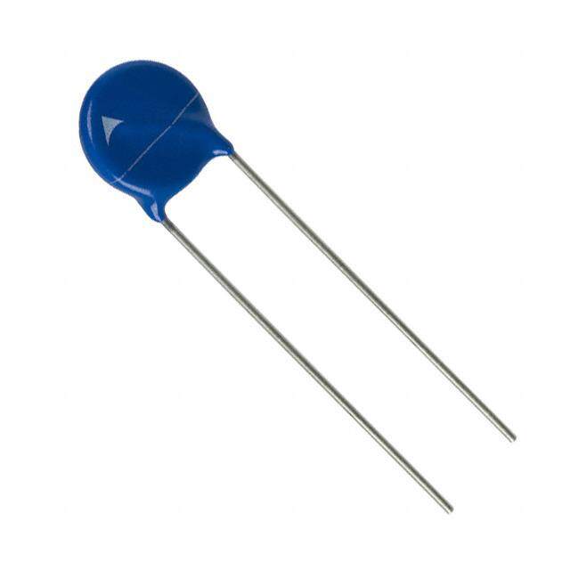
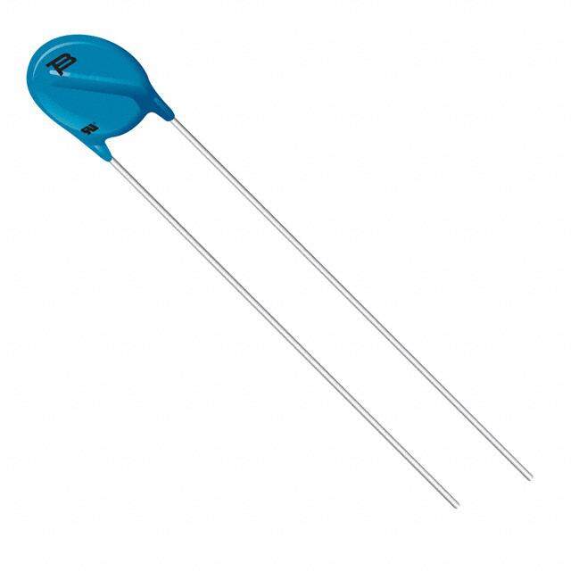
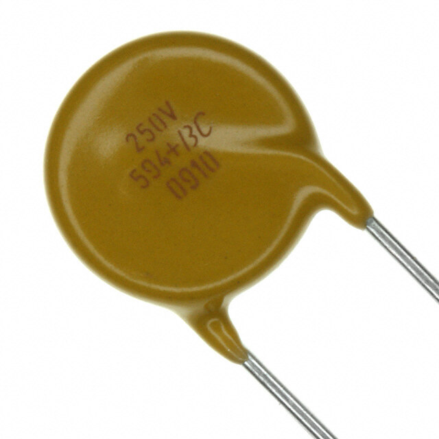
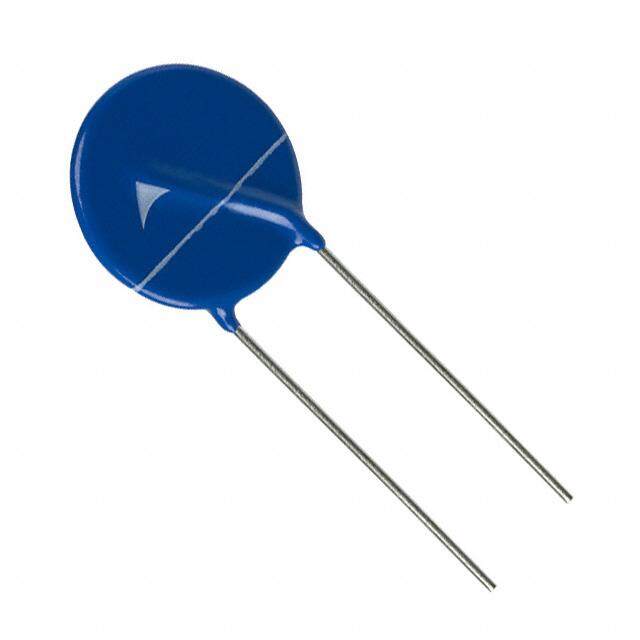
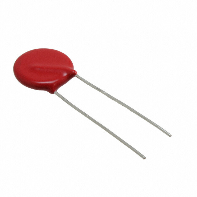
ICGOO电子元器件商城为您提供V150LS2P由Littelfuse设计生产,在icgoo商城现货销售,并且可以通过原厂、代理商等渠道进行代购。 V150LS2P价格参考¥0.85-¥0.85。LittelfuseV150LS2P封装/规格:TVS - 变阻器,MOV, 240V 1.2kA Varistor 1 Circuit Through Hole Disc 7mm。您可以下载V150LS2P参考资料、Datasheet数据手册功能说明书,资料中有V150LS2P 详细功能的应用电路图电压和使用方法及教程。
Littelfuse Inc. 的型号 V150LS2P 是一款金属氧化物压敏电阻(MOV),属于瞬态电压抑制器(TVS)的一种。该器件主要用于保护电子设备免受高能量瞬态电压的损害,如雷击浪涌、静电放电(ESD)和电感负载开关引起的电压尖峰。

V150LS2P 常用于以下应用场景:

1. 电源输入端保护:广泛应用于交流电源入口处,为家电、工业设备、UPS电源等提供过压保护。
2. 通信设备防护:用于保护电信设备、网络交换机和路由器免受外部浪涌影响。
3. 消费电子产品:如电视、空调、洗衣机等家用电器中,防止因电网波动或雷击导致的损坏。
4. 工业控制系统:在PLC、变频器、电机控制器等工业系统中保障控制电路安全。
5. 新能源领域:适用于太阳能逆变器、风力发电设备等新能源系统中的过电压保护。

该MOV具有较高的能量吸收能力和快速响应特性,适合需要较强浪涌防护能力的应用场合。
| 参数 | 数值 |
| 产品目录 | |
| 描述 | VARISTOR 212V 1.2KA DISC 7MM |
| 产品分类 | |
| 品牌 | Littelfuse Inc |
| 数据手册 | |
| 产品图片 |
|
| 产品型号 | V150LS2P |
| rohs | 无铅 / 符合限制有害物质指令(RoHS)规范要求 |
| 产品系列 | LS |
| 其它名称 | F5595CT |
| 包装 | 剪切带 (CT) |
| 变阻器电压 | 212V |
| 封装/外壳 | 圆盘 7mm |
| 最大AC电压 | 150VAC |
| 最大DC电压 | 200VDC |
| 标准包装 | 1 |
| 电流-浪涌 | 1.2kA |
| 电路数 | 1 |
| 能量 | 13J |


- 商务部:美国ITC正式对集成电路等产品启动337调查
- 曝三星4nm工艺存在良率问题 高通将骁龙8 Gen1或转产台积电
- 太阳诱电将投资9.5亿元在常州建新厂生产MLCC 预计2023年完工
- 英特尔发布欧洲新工厂建设计划 深化IDM 2.0 战略
- 台积电先进制程称霸业界 有大客户加持明年业绩稳了
- 达到5530亿美元!SIA预计今年全球半导体销售额将创下新高
- 英特尔拟将自动驾驶子公司Mobileye上市 估值或超500亿美元
- 三星加码芯片和SET,合并消费电子和移动部门,撤换高东真等 CEO
- 三星电子宣布重大人事变动 还合并消费电子和移动部门
- 海关总署:前11个月进口集成电路产品价值2.52万亿元 增长14.8%


PDF Datasheet 数据手册内容提取
Metal-Oxide Varistors (MOVs) Radial Lead Varistors > C-III Varistor Series C-III Varistor Series RoHS Description The C-III Varistor Series of Metal-Oxide Varistors (MOVs) are specifically designed for applications requiring high surge energy absorption ratings and superior multiple pulse absorption rating. This is achieved through a special dielectric material formulation which also results in higher repetitive surge ratings than other MOV types. The C-III Varistor Series is primarily intended for use in AC line Surge Protection Device (SPD) product and other similar applications requiring high transient energy and peak current capability in a relatively small package size. Agency Approvals Features Agency File • Lead–free, Halogen- • Available in tape and Agency Agency Approval Number Free and RoHS reel for automatic UL1449 E320116 compliant insertion; Also available CECC 42201-006 with crimped and/or • High energy IEC 61051-1 trimmed lead styles IEC 61051-2 116895 absorption capability IEC 60950-1 (Annex Q) for 14mm and W 40J to 530J (2ms) • No derating up to 20mm only TM 85ºC ambient CECC 42201-006 • High pulse life rating IEC 61051-1 • The C-III Series is IEC 61051-2 E1273/F • High peak pulse supplied in 10mm, IEC 60950-1 (Annex Q) for 14mm and current capability 14mm and 20mm 20mm only I 3500A to disc versions with TM 10,000A (8/20µs) various lead options • Wide operating voltage range V 130V to 1000V M(AC)RMS Additional Information Datasheet Resources Samples Absolute Maximum Ratings • For ratings of individual members of a series, see Device Ratings and Specifications chart Continuous C-III Series Units Steady State Applied Voltage AC Voltage Range (V ) 130 to 1000 V M(AC)RMS Transients Single-Pulse Peak Current (I ) 8/20µs Wave TM 3500 to 10,000 A (See Peak Pulse Current Test Waveform) Single-Pulse Energy Range (W ) 2ms Rectangular Wave 40 to 530 J TM Operating Ambient Temperature Range (T) -55 to +85 ºC A Storage Temperature Range (T ) -55 to +125 ºC STG Temperature Coefficient (aV) of Clamping Voltage (V) at Specified Test Current <0.01 %/ºC C Hi-Pot Encapsulation (COATING Isolation Voltage Capability) 2500 V COATING Insulation Resistance 1000 MΩ CAUTION: Stresses above those listed in "Absolute Maximum Ratings" may cause permanent damage to the device. This is a stress only rating and operation of the device at these or any other conditions above those indicated in the operational sections of this specification is not implied. © 2019 Littelfuse, Inc. Specifications are subject to change without notice. Revised: 12/17/19
Metal-Oxide Varistors (MOVs) Radial Lead Varistors > C-III Varistor Series C-III Series Ratings Maximum Ratings (85 °C) Specifications (25 °C) Continuous Transient Maximum Varistor Voltage Clamping Duty Cycle Surge Part Number Branding DSiizsec Maximum Withstanding Pe(a8k/ 2C0uµrsre)nt at 1mCuArr DenCt Test (V8o/2lt0aµgse) Rating (mm) VRMS Energy (2ms) VM(AC) WTM ( ) ITM1 ITM2 VN VN V I 3kA 750A (V) (J) 1 Pulse 2 Pulses Min Max (VC) (Ap) (8/20µs) (8/20µs) (A) (A) (V) (V) # Pulses # Pulses V130LA5CP P130L5C 10 130 40 3500 3000 184.5 225.5 340 25 2 20 V130LA10CP P130L10C 14 130 80 6500 5000 184.5 225.5 340 50 10 80 V130LA20CP P130L20C 20 130 200 10000 7000 184.5 225.5 340 100 20 120 V130LA20CPX325 P130X325 20 130 200 10000 7000 190 220 325 100 20 120 V140LA5CP P140L5C 10 140 45 3500 3000 198 242 360 25 2 20 V140LA10CP P140L10C 14 140 90 6500 5000 198 242 360 50 10 80 V140LA20CP P140L20C 20 140 210 10000 7000 198 242 360 100 20 120 V140LA20CPX340 P140X340 20 140 210 10000 7000 198 230 340 100 20 120 V150LA5CP P150L5C 10 150 50 3500 3000 216.0 264.0 395 25 2 20 V150LA10CP P150L10C 14 150 100 6500 5000 216.0 264.0 395 50 10 80 V150LA20CP P150L20C 20 150 215 10000 7000 216.0 264.0 395 100 20 120 V150LA20CPX360 P150X360 20 150 215 10000 7000 216 243 360 100 20 120 V175LA5CP P175L5C 10 175 55 3500 3000 243 297 455 25 2 20 V175LA10CP P175L10C 14 175 110 6500 5000 243 297 455 50 10 80 V175LA20CP P175L20C 20 175 220 10000 7000 243 297 455 100 20 120 V175LA20CPX425 P175X425 20 175 220 10000 7000 247 285 425 100 20 120 V230LA10CP P230L10C 10 230 60 3500 3000 324 396 595 25 2 20 V230LA20CP P230L20C 14 230 125 6500 5000 324 396 595 50 10 80 V230LA40CP P230L40C 20 230 280 10000 7000 324 396 595 100 20 120 V230LA40CPX570 P230X570 20 230 280 10000 7000 324 384 570 100 20 120 V250LA10CP P250L10C 10 250 65 3500 3000 351 429 650 25 2 20 V250LA20CP P250L20C 14 250 135 6500 5000 351 429 650 50 10 80 V250LA40CP P250L40C 20 250 300 10000 7000 351 429 650 100 20 120 V250LA40CPX620 P250X620 20 250 300 10000 7000 354 413 620 100 20 120 V275LA10CP P275L10C 10 275 70 3500 3000 387 473 710 25 2 20 V275LA20CP P275L20C 14 275 145 6500 5000 387 473 710 50 10 80 V275LA40CP P275L40C 20 275 320 10000 7000 387 473 710 100 20 120 V275LA40CPX680 P275X680 20 275 320 10000 7000 389 453 680 100 20 120 V300LA10CP P300L10C 10 300 75 3500 3000 423.0 517.0 775 25 2 20 V300LA20CP P300L20C 14 300 155 6500 5000 423.0 517.0 775 50 10 80 V300LA40CP P300L40C 20 300 335 10000 7000 423.0 517.0 775 100 20 120 V300LA40CPX745 P300X745 20 300 335 10000 7000 420 490 745 100 20 120 V320LA10CP P320L10C 10 320 80 3500 3000 462.0 558.0 850 25 2 20 V320LA20CP P320L20C 14 320 165 6500 5000 462.0 558.0 850 50 10 80 V320LA40CP P320L40C 20 320 345 10000 7000 462.0 558.0 850 100 20 120 V320LA40CPX810 P320X810 20 320 345 10000 7000 462 540 810 100 20 120 V385LA10CP P385L10C 10 385 85 3500 3000 558 682 1025 25 2 20 V385LA20CP P385L20C 14 385 175 6500 5000 558 682 1025 50 10 80 V385LA40CP P385L40C 20 385 370 10000 7000 558 682 1025 100 20 120 V420LA10CP P420L10C 10 420 90 3500 3000 612.0 748.0 1120 25 2 20 V420LA20CP P420L20C 14 420 185 6500 5000 612.0 748.0 1120 50 10 80 V420LA40CP P420L40C 20 420 390 10000 7000 612.0 748.0 1120 100 20 120 V460LA10CP P460L10C 10 460 95 3500 3000 643.5 786.5 1190 25 2 20 V460LA20CP P460L20C 14 460 190 6500 5000 643.5 786.5 1190 50 10 80 V460LA40CP P460L40C 20 460 430 10000 7000 643.5 786.5 1190 100 20 120 V480LA10CP P480L10C 10 480 95 3500 3000 675.0 825.0 1240 25 2 20 V480LA40CP P480L40C 14 480 195 6500 5000 675.0 825.0 1240 50 10 80 © 2019 Littelfuse, Inc. Specifications are subject to change without notice. Revised: 12/17/19
Metal-Oxide Varistors (MOVs) Radial Lead Varistors > C-III Varistor Series C-III Series Specifications (continued from previous page) V480LA80CP P480L80C 20 480 420 10000 7000 675.0 825.0 1240 100 20 120 V510LA10CP P510L10C 10 510 98 3500 3000 738.0 902.0 1350 25 2 20 V510LA40CP P510L40C 14 510 205 6500 5000 738.0 902.0 1350 50 10 80 V510LA80CP P510L80C 20 510 440 10000 7000 738.0 902.0 1350 100 20 120 V550LA10CP P550L10C 10 550 98 3500 3000 792.0 968.0 1435 25 2 20 V550LA40CP P550L40C 14 550 210 6500 5000 792.0 968.0 1435 50 10 80 V550LA80CP P550L80C 20 550 450 10000 7000 792.0 968.0 1435 100 20 120 V575LA10CP P575L10C 10 575 100 3500 3000 819.0 1001.0 1500 25 2 20 V575LA40CP P575L40C 14 575 230 6500 5000 819.0 1001.0 1500 50 10 80 V575LA80CP P575L80C 20 575 460 10000 7000 819.0 1001.0 1500 100 20 120 V625LA10CP P625L10C 10 625 105 3500 3000 900 1100 1650 25 2 20 V625LA40CP P625L40C 14 625 235 6500 5000 900 1100 1650 50 10 80 V625LA80CP P625L80C 20 625 490 10000 7000 900 1100 1725 100 20 120 V660LA10CP P660L10C 10 660 110 3500 3000 972.0 1188.0 1820 25 2 20 V660LA50CP P660L50C 14 660 240 6500 5000 972.0 1188.0 1820 50 10 80 V660LA80CP P660L80C 20 660 510 10000 7000 972.0 1188.0 1820 100 20 120 V680LA10CP P680L10C 10 680 115 3500 3000 990.0 1210.0 1860 25 2 20 V680LA80CP P680L80C 14 680 240 6500 5000 990 1210 1820 50 10 80 V680LA100CP P680L100C 20 680 520 10000 7000 990 1130 1700 100 20 120 V1000LA80CP P1000L8C 14 1000 260 6500 5000 1500 1800 2700 50 10 80 V1000LA160CP P1000L16C 20 1000 530 10000 7000 1500 1800 2700 100 20 120 NOTES: - Average power dissipation of transients not to exceed 0.6W and 1W for model sizes 14mm and 20mm, respectively. - 7mm parts also available-contact factory for further information - For additional or intermediary voltage ratings contact factory Phenolic Coating Option -- C-III Series Varistors for Hi-Temperature Operating Conditions: • Phenolic Coated CIII Series devices are available with improved maximum operating maximum temperature 125ºC • These devices also have improved temperature cycling performance capability. • Ratings and Specifications are as per standard except Hi–Pot Encapsulation (Isolation Voltage Capability)=500V. • To order: add X1347 to part number (e.g. V230LA40CPX1347) • These devices are not UL, CSA, VDE or CECC certified. • Contact factory for further details. • Product marking: LF 9 P230P40C Lead-Free, YYWW Phenolic Coated Halogen-Free Option & RoHS Compliant Identifier Indicator © 2019 Littelfuse, Inc. Specifications are subject to change without notice. Revised: 12/17/19
Metal-Oxide Varistors (MOVs) Radial Lead Varistors > C-III Varistor Series Figure 1. Current Energy and Power Dissipation Ratings Should transients occur in rapid succession, the average device. The operating values of a MOV need to be derated power dissipation is the energy (watt-seconds) per pulse at high temperatures as shown above. Because varistors times the number of pulses per second. The power so only dissipate a relatively small amount of average power developed must be within the specifications shown on the they are not suitable for repetitive applications that involve Device Ratings and Specifications Table for the specific substantial amounts of average power dissipation. 1A - Power Derating for Epoxy Coated 1B - Power Derating for Phenolic Coated 100 100 UE 90 UE 90 VAL 80 VAL 80 D 70 D 70 E E AT 60 AT 60 R R OF 50 OF 50 NT 40 NT 40 E E RC 30 RC 30 PE 20 PE 20 10 10 0 0 -55 50 60 70 80 90 100 110 120 130 140 150 -55 50 60 70 80 90 100 110 120 130 140 150 AMBIENT TEMPERATURE (oC) AMBIENT TEMPERATURE (oC) FIGURE 1. CURRENT, ENERGY AND POWER DERATING FIGURE 1. CURRENT, ENERGY AND POWER DERATING Figure 2. Peak Pulse Current Test Waveform CURVE CURVE E 100 U AL 0 = Virtual Origin of Wave V 90 1 10,000 T = Time from 10% to 90% of Peak AK MODEL SIZE = 10mm T1 = Rise Time = 1.25 x T OF PE 50 V460LA10C(P) TE2x =am Dpelcea y- FToimr aen 8/20 µs Current Waveform: T V320LA10C(P) mum Voltage (V)1,000 VPERCEN250LA1100C(P) V275LA10CV(P3)00LA10C(P) 82µ0sµ s= = T 1T 2= = R Diseec Taiym Teime Maxi V230LOA110C(P) T TIME T1 T2 V175LA5C(P) Transient V-I ChaOra1c =t eVriritsutail csO riCVg1iun40 rLAvo5Cfe (PWs) aVv1e50LA5C(P) Pulse Rating Curves T = VT1im30LeA 5CF(Pr)om 10% to 90% of Peak 100 0.001 0.01 T10. 1= Virtua1l Front1 0time 10=0 1.25 10•00 t 10000 Figure 3. MaximuTm2 = C VliartumPaelap k AiTmnimpgeere Vs (tAoo) lHtaalgf eV aflouer 1(I0mmpulmse PDaurrtastion) Figure 4. Repetitive Surge Capability for 10mm Parts Example: For an 8/20µs Current Waveform: V130LA5C(P8) –s V=6 T251L =A 1V0irCtu(aPl) Front Time V130LA5C(P)-V320LA10C(P) 1100000000 20 s = T2 = Virtual Time to Half Value 10,000 MT1A3O0 = Dt o-E5 L65F 2oS5CIIZVG TEM OU =( A8 RC150)oE MRC AMTIN2G. PMEAAXVKIMO LUTMAPG CUELALMSPE CURRENT TEST WAVEFORM NT (A)1,000 1215 MTAO =D -E5L5 oSCIZ TEO = 8 150omCm MUM PEAK VOLTAGE (V)MUM PEAK VOLTAGE (V)11000000 625 550 510 460 440 420 385 320 300 275 250 230 AK SURGE CURRE 100 ∞110032 101401506 MAXIMAXI D PE 10 E T A 130 140 150 175 R 1 110000 10 100 1,000 10,000 00..000011 00..0011 00..11 11 1100 110000 11000000 1100000000 PPEEAAKK CCUURRRREENNTT ((AA)) SURGE IMPULSE DURATION (μs) © 2019 Littelfuse, Inc. Specifications are subject to change without notice. 10,000 Revised: 12/17/19 1 MODEL SIZE = 14mm 15 2 TA = -55oC TO 85oC A) NT (1,000 102 RE 103 R CU 104 E RG 100 ∞ U S K A E P D 10 E T A R 1 10 100 1,000 10,000 SURGE IMPULSE DURATION (μs) 10,000 12 MTAO =D -E5L5 oSCIZ TEO = 8 250omCm T (A) 11052 EN1,000 103 R UR 104 C GE ∞ R 100 U S K A E P ED 10 T A R 1 10 100 1,000 10,000 SURGE IMPULSE DURATION (μs)
10,000 10,000 MODEL SIZE = 10mm RENT (A)NT (A)11,,000000 11212155 1TMT0AA4O ==D --E555L5o oSCCI ZT TEOO = 88 5150oomCCm Metal-Oxide VaRGE CURE CURREris10t0or11s11000032 32(MOVs) 101140011550066 Radial Lead VaristorsEAK SUK SURG >1 0C0-II∞∞I Varistor Series PA RATED TED PE 1100 A R 1 1 10 100 1,000 10,000 Transient V-I Characteristics Curves Pulse Rating Curves 10 SURG1E0 0IMPULSE DURAT1I,O00N0 (μs) 10,000 SURGE IMPULSE DURATION (μs) Figure 5. Maximum Clamping Voltage for 14mm Parts Figure 6. Repetitive Surge Capability for 14mm Parts V130LA10C(P) – V420LA20C(P) V130LA10C(P)-V420LA20C(P) 10,000 10,000 10,000 1 MODEL SIZE = 14mm MODEL SIZE = 14mm 15 12 TMAO =D -E55Lo SCI ZTEO =8 514omCm A) 15 2 TA = -55oC TO 85oC V385LAV204C2V0(4PL6)A02L0AC2(0PC)(P) V230LA20C(P) RENT (NT (A)11,,000000 111000232 Maximum Voltage (V)1,000 V250LAV202C75(PL)A20C(P)V300LAV2302C0(PLA)20C(P) EAK SURGE CURK SURGE CURRE 110000 1∞11∞000434 PA V15V01L7A51L0AC1(0PC)(P) RATED ATED PE 1100 V140LA10C(P) R V130LA10C(P) 1 1000.001 0.01 0.1 1 10 100 1000 10000 11100 SURG11E00 00IMPULSE DURAT11I,,O0000N00 (μs) 1100,,000000 Peak Amperes (A) SURGE IMPULSE DURATION (μs) Figure 7. Maximum Clamping Voltage for 20mm Parts Figure 8. Repetitive Surge Capability for 20mm Parts V130LA5C(P) - V680LA10C (P) V130LA20C(P)-V680LA100C(P) m Voltage (V)10,000 V385LVA44M200COL(ADP4E)0LC S(PIZ)E VV= 44268000mLLAAm4800CC((PP))V510LA80VC5(7P5)LVAV682065C6VL0(PAL6)A88001L0CA0(PC1)0(P0)C(P) VVVVVVV222111175375435005000LLLLLLLURGE CURRENT (A)AAAAAAAGE CURRENT (A)44422221100000000101CCCCCCC,,,,001000000000000 111∞1111∞100000055342342 1122 MTMTAAOO ==DD -E-E55L5L5 o SoSCCIIZ ZT TEEOO = = 8 8 252500oommCCmm Maximu1,000 VV332000LLEAK SAAK SUR4400CC100 V175LVA22300CL(PA)40C(PV)250LA40CVV(VP233)720500LLLAAA444000CCC((P(PP))) VVVV544318280005LLLLRATED PAAAARATED PEA88440000CCCC 1100 100 V130LA20C(PV)140LA20C(P) V150LA20C(P) VV652755LLAA8800CC 111100 SURG11E00 00IMPULSE DURAT11I,,O0000N00 (μs) 1100,,000000 0.001 0.01 0.1 1 10 100 1000 10000 V660LA100C SURGE IMPULSE DURATION (μs) Peak Amperes (A) Figure 9. Maximum Clamping Voltage for Low Clamping Voltage Parts Note: Repetitive surge capability is qualified and tested based on 8/20us current waveform (not combination waveform) and UL1449 40.7.3 (Edition 4) V130LA20CX325(P) - V300LA40CX245 (P) test condition. 10,000 V300LA40CX810(P) V) Maximum Voltage (1,000 V230LA40CXV527500(LPA)40CX620(PV)275LA4V03C0X06L8A04(0PC)X745(P) V175LA20CX425(P) V150LA20CX360(P) V140LA20CX340(P) V130LA20CX325(P) 100 0.001 0.01 0.1 1 10 100 1000 10000 Peak Amperes (A) © 2019 Littelfuse, Inc. Specifications are subject to change without notice. Revised: 12/17/19
Metal-Oxide Varistors (MOVs) Radial Lead Varistors > C-III Varistor Series Wave Solder Profile Figure 10. Non Lead–free Profile Figure 11. Lead–free Profile 300 300 Maximum Wave 260C Maximum Wave 240C 250 250 C) C) E (º 200 E (º 200 R R U U T T A 150 A 150 R R E E P P M 100 M 100 E E T T 50 50 0 0 0 0.5 1 1.5 2 2.5 3 3.5 4 0 0.5 1 1.5 2 2.5 3 3.5 4 TIME(MINUTES) TIME(MINUTES) Physical Specifications Environmental Specifications Lead Material Copper Clad Steel Wire Operating/Storage -55°C to +85°C/-55°C to +125°C Temperature Soldering Solderability per MIL–STD–202, +85°C, 85% RH, 1000 hours Characteristics Method 208 Humidity Aging +/-10% typical voltage change Cured, flame retardant epoxy polymer meets Insulating Material +85°C to -40°C, 5 times UL94V–0 requirements Thermal Shock +/-10% typical voltage change Marked with LF, voltage, UL/CSA Logos, and Device Labeling date code Solvent Resistance MIL–STD–202, Method 215 Moisture Sensitivity Level 1, J-STD-020 © 2019 Littelfuse, Inc. Specifications are subject to change without notice. Revised: 12/17/19
Metal-Oxide Varistors (MOVs) Radial Lead Varistors > C-III Varistor Series AC Bias Reliability The C-III Series MOVs were designed for use on the AC Figure 12. High Temperature Operating Life 125ºC for 1000 line. The varistor is connected across the AC line and is Hours at Rated Bias biased with a constant amplitude sinusoidal voltage. It should be noted that the definition of failure is a shift in the 300 nominal varistor voltage (V ) exceeding +/-10%. Although this type of varistor is still fNunctioning normally after this V130LA20C tmolaegrnanituced ew oilfl sbheigfti,n d teov dicisessi paat tteh em loorwe epro ewxetrre.mities of VN A (V) 250 m 1 200 Because of this possibility, an extensive series of AT M statistically designed tests were performed to determine NO150 the reliability of the C-III type of varistor under AC bias V combined with high levels of temperature stress. To 100 date, this test has generated over 50,000 device hours of 0 100 200 300 400 500 600 700 800 900 1000 1100 operation at a temperature of 125ºC, although only rated at TIME (HOURS) Figure 12 85ºC. Changes in the nominal varistor voltage, measured at FIGURE 8. HIGH TEMPERATURE OPERATING LIFE 125oC 1mA, of less than 2% have been recorded, as displayed in FOR 1000 HOURS AT RATED BIAS the diagram at right. Transient Surge Current/Energy Transient Capability The transient surge rating serves as an excellent figure Figure 13 & 14. Typical Repetitive Surge Current Capability of of merit for the C-III varistor. This inherent surge handling C-III Series MOVs capability is one of the C-III varistor’s best features. The enhanced surge absorption capability results from improved process uniformity and enhanced construction. E AT 3kAGE AT 3kA 545405050000 Tipmhroepc rheoosvsemedos cg aoernnete rcoitoly no otvrfei btruh ttehin erga sw fina cmtetoarirtnseg rtV3V3 ioaakk11lAAn 33 tp0 0 dh((LL88o iAA//asw2222s 0000idsmμμCCssee))pmr raobnvlyde ment. E AT 3kAGE AT 3kA 545405050000 V3V3kk11AA330 0 ((LL88AA//22220000μμCCss)) GA GA AT AT OLTVOL 440000 In the low power AC mains environment, industry OLTVOL 440000 G VNG standards (UL, IEC, NEMA and IEEE) all suggest that the G VNG PINMPI 335500 worst case surge occurrence will be 3kA. Such a transient PINMPI 335500 LAMCLA e((RRvAAeTTnEEtDD mFFOOaRRy 22 o00 cPPcUUuLLSSr EEuSSp)) to five times over the equipment life LAMCLA ((RRAATTEEDD FFOORR 2200 PPUULLSSEESS)) C 300 time (approximately 10 years). While the occurences of C 300 3000 10 20 30 40 50 60 70 80 90 100 110 120 3000 5 10 15 20 25 30 0 fiv10e 32k0A t3r0ansN4i0eUnMt5Bs0E Ris O 6t0Fh SeU 7rR0eGqEu8S0ired90 ca1p00ab1i1li0ty1,2 t0he rated, 0 5 1N0UMBER 1O5F SURGE2S0 25 30 NUMBER OF SURGES NUMBER OF SURGES repetitive surge current for the C-III Series is 20 pulses FIGURE 9. TYPICAL REPETITIVE SURGE CURRENT FIGURE 9. TYPICAL REPETITIVE SURGE CURRENT FIGURfEo r9 .thTeY P2I0CAmLm R EuPnEiTtsIT aIVnEd S1U0R pGuEls CeUsR fRoEr NthTe 14mm Series. FIGURE 9. TYPICAL REPETITIVE SURGE CURRENT CAPABILITY OF C-III SERIES MOVs CAPABILITY OF C-III SERIES MOVs CAPABILITY OF C-III SERIES MOVs CAPABILITY OF C-III SERIES MOVs As a measure of the inherent device capability, samples CLAMPING VOLTAGE AT 750ACLAMPING VOLTAGE AT 750A 65544336554433050505005050500000000000000000((RRoaptvrStnheoAAo fueawTT ec 22lmlgtrEEtso00 heoaDDld00eirpepggr deFFssl eeiOOeve2,bt t,44RR isd0el icc00et m ,11ma00eiao v22cacs efe00cmhh se at hPP ash 66s sUUoarVnu00euehLLfr00g1r a SSrpo3g23eeEEcewke0SS0dsttAe ))m 88nL ioita00r,n Aici 00tmvist n c2aeh1t ui0n 0teSc11thryC0r00rsereea 00e. Aor d00n inCuwfe,es cphsotiva11eehp afi22Vscs neen00l 1e etn 00rgod 7s sesefd77e5 s11 uVVg55wsi7v44L a0011rl t00i5iAAgA77giehcg00n550 errea2i(( LLabe88Atsn AA0//11mhcl 22.e22 s66Cth e3000000Ae u μμ aCC c%00awscbgssrht))talj aaa ee.rcw22 iimnrnAcg00tegeet00,hfp e00terrtsteiiedh.n su ri entg bti2ro c jee0 s c wteads CLAMPING VOLTAGE AT 750ACLAMPING VOLTAGE AT 750A 65544336554433050505005050500000000000000000((RRAATTEEDD FF55OO00RR 112200 PP11UUN00LL00USSMEESSB))ER11 O5500F SURGE2200S00 77VV550011AA77225555 ((LL0088AA//22220000μμCCss))330000 NUMBER OF SURGES NUMBER OF SURGES after 120 pulseNsU,M aBsE Rs OhFo wSUnR GinE Sthe lower diagram at right. FIGURE 10. TYPICAL REPETITIVE SURGE CURRENT FIGURE 10. TYPICAL REPETITIVE SURGE CURRENT FIGURE 10. TYPICAL REPETITIVE SURGE CURRENT FIGURE 10. TYPICAL REPETITIVE SURGE CURRENT In boCCtAAh PPcAAaBBsIIeLLIIsTT YYth OOeFF inCC--hIIIIeII rSSeEEnRRtII EEdSSe vMMicOOeVV sscapability is far CCAAPPAABBIILLIITTYY OOFF CC--IIIIII SSEERRIIEESS MMOOVVss in excess of the expected worst case scenario. © 2019 Littelfuse, Inc. Specifications are subject to change without notice. Revised: 12/17/19
Metal-Oxide Varistors (MOVs) Radial Lead Varistors > C-III Varistor Series Product Dimensions (mm) ØD A *SEATING A PLANE TRIM 25.4(1.00) Min. for Bulk pack(LA) only L TRIM 25.4 Øb (1.00) Min. CRCIRMIMPPEEDD A ANNDD T RIMTRMIMEDM ELEDA LDESA D Radial lead types can be supplied with combination preformed crimp and trimmed leads. This option is e supplied to the dimensions shown below. e1 E *Seating plane interpretation per IEC-60717 V Voltage 10mm Size 14mm Size 20mm Size Dimension RMS Model Min. Max. Min. Max. Min. Max. A All 12.0 (0.472) 16.0 (0.630) 13.5 (0.531) 20.0 (0.787) 17.5 (0.689) 28.0 (1.102) ØD All 10.0 (0.394) 12.5 (0.492) 13.5 (0.531) 17.0 (0.669) 17.5 (0.689) 23.0 (0.906) e All 6.5 (0.256) 8.5 (0.335) 6.5 (0.256) 8.5 (0.335) 6.5 (0.256) 8.5 (0.335) 130 - 320 1.5 (0.059) 5.5 (0.216) 1.5 (0.059) 4.5 (0.177) 1.5 (0.059) 4.5 (0.177) e 385 - 680 2.5 (0.098) 7.5 (0.295) 2.5 (0.098) 7.5 (0.295) 2.5 (0.098) 7.5 (0.295) 1 > 680 4.5 (0.177) 9.5 (0.374) 4.5 (0.177) 9.5 (0.374) 4.5 (0.177) 9.5 (0.374) 130 - 320 7.3 (0.287) 7.3 (0.287) 7.3 (0.287) E 385 - 680 - 11.0 (0.433) - 11.0 (0.433) - 11.0 (0.433) > 680 14.0 (0.551) 14.0 (0.551) 14.0 (0.551) 130 - 625 0.76 (0.030) 0.86 (0.034) Øb 0.76 (0.030) 0.86 (0.034) 0.76 (0.030) 0.86 (0.034) >625 0.95 (0.037) 1.05 (0.041) A All – 19.5 (0.768) – 23.5 (0.925) – 30.0 (1.18) TRIM L All 2.41 (0.095) 4.69 (0.185) 2.41 (0.095) 4.69 (0.185) 2.41 (0.095) 4.69 (0.185) TRIM Dimensions are in millimeters (inches) 1. 10mm lead spacing also available. See additional lead style options. 2. 7mm and 12mm devices also available upon request. Contact factory for details. 3. 1000V parts supplied with lead wire of diameter 1.00 -/+ 0.05 (0.039 -/+ 0.002). © 2019 Littelfuse, Inc. Specifications are subject to change without notice. Revised: 12/17/19
Metal-Oxide Varistors (MOVs) Radial Lead Varistors > C-III Varistor Series Tape and Reel Specifications • (available for voltage ratings up to 550V only) Model Size Symbol Description 10mm 14mm 20mm CRIMPED LEADS "LT" P Pitch of Component 25.4 -/+1.0 P Feed Hole Pitch 12.7 -/+ 0.2 P2 P E 0 P2 PDP DP DH E DH P1 Feed Hole Center to Pitch 8.85 -/+ 0.8 DP DP DH DH Hole Center to Component P2 P E P2 Center 12.7 -/+ 0.7 DP DP DH DH F Lead to Lead Distance 7.50 -/+ 0.8 h Component Alignment 2.00 Max HH11 S S PPEELLAAAATTNNIINNEEGG CC W0 W2 W1 W Tape Width 18.25 -/+ 0.75 H0 b W0 W2 W1 W Hold Down Tape Width 12.0 -/+ 0.3 H1 H0 S PELAATNINEG bC 0 W Hole Position 9.125 -/+ 0.625 W0 W2 W1 W 1 H0 b W W Hold Down Tape Position 0.5 Max D0 2 D0 P1 F t H Height From Tape Center To 19.0 -/+1.0 P1P0 F t W Component Base D0 P0 H Seating Plane Height 16.0 -/+ 0.5 Crimped Leads "LT" P1 F t 0 46.5 Crimped Leads "LT" H Component Height 36 Max 40 Max P0 1 Max Crimped Leads "LT" STRAIGHT LEADS "LS" D0 Feed Hole Diameter 4.0 -/+ 0.2 P E P2 PDP DP E t Total Tape Thickness 0.7 -/+ 0.2 P2 DH DH DP DP DH DH p Component Alignment 3° Max P E P2 DP DP U Under crimp Width 8.0 Max DH DH H1 H1 W0 W2 W1 H b W0 W2 W1 H H1 b W0 W2 W1 W H b W D0 D0 P1 F t W P1 F t P0 D0 Straight Leads "LS" P0 P1 F t Straight Leads "LS" P0 Straight Leads "LS" P2 P E PU2 NDER-CRPDIPMPED LEADPDDSH "LUE" DH DP DP DH DH P2 P E DP DP DH DH H1 U H1 U W0 W2 W1 Ho b W0 W2 W1 Ho H1 b U W0 W2 W1 W Ho b W D0 D0 P1 F t W PP10 F t D0 P0 Under-crimped Leads "PL1U" F t Under-crimped Leads "LU" P0 Under-crimped Leads "LU" © 2019 Littelfuse, Inc. Specifications are subject to change without notice. Revised: 12/17/19
Metal-Oxide Varistors (MOVs) Radial Lead Varistors > C-III Varistor Series Part Numbering System BASE PART CODES OPTION CODES (See Ratings & Specifications tables and notes below) (See notes below) V XXXX LA XX C P XXXXX For “ VARISTOR” See OPTIONS CODES notes below VM(AC) For standard parts, use the BASE PART designator only. (Three or four digits -- 130V to 1,000V) For parts with non-standard options (such as additional form, packaging SERIES + PACKAGING / LEAD STYLE and lead space options), use BASE PART + OPTION CODE. DESIGNATOR OPTION CODE items are subject to availability and minimum order (See BASE PART CODES notes below) LA = Bulk Pack / Straight Leads (standard) requirements. Please contact a Littelfuse products representative for LC = Bulk Pack / Crimped and Trimmed Leads additional information or questions LS = Tape and Reel / Straight Leads LT = Tape and Reel / Crimped Leads LU = Tape and Reel / Under-Crimped Leads RELATIVE ENERGY INDICATOR (One or Two Digits) C-III SERIES DESIGNATOR LEAD-FREE, HALOGEN-FREE AND RoHS COMPLIANT INDICATOR Ordering Notes: BASE PART CODES: OPTION CODES: Series + Packaging / Lead Style Designators: X10: 10MM LEAD SPACING OPTION -- Ordering examples: For 10 (-/+1)mm lead spacing (available on 20mm Straight Lead Straight Lead Crimped & Under-Crimp diameter models only), append standard model Bulk Pack Trimmed Lead Lead Tape & Reel BASE PART number with "X10." Example: (standard) Bulk Pack Tape & Reel V130LA20CP V130LS20CP V130LC20CP V130LU20CP Standard Model Order As Crimped leads are standard on LA Series varistors supplied in V130LA20CP V130LA20CPX10 tape and reel, denoted with "LT." X2855: Nickel Barrier COATED WIRE OPTION -- "LC" style is supplied in bulk only. All standard parts use tinned copper clad steel wire. "LU" style is supplied in tape & reel only. Nickel Barrier Coated wire is available as an option, consisting of Copper wire with a flashing of Nickel For crimped leads without trimming and any varitions other than followed by a top coating of Tin. To order append standard that described above, please contact Littelfuse. model BASE PART number with "X2855." Example: Packaging and Quantities: Littelfuse C-III Series varistors are shipped standard in bulk pack Standard Model Order As with straight leads and lead spacing outlined in the Package V130LA20CP V130LA20CPX2855 Dimensions section of this data sheet. Tape & Reel Quantities: X1347: Hi-Temperature phenolic coating option -- Quantity Per Reel Phenolic Coated C-III Series devices are available with improved Device Size Voltage "T" Reel "S" Reel "U"Reel maximum operating maximum temperature of 125°C. 10mm ALL 500 500 500 To order, add X1347 to end of part number ≤ 275V 500 500 500 (Example: V230LA40CPX1347). 14mm ≥ 275V 400 400 400 For additional information please refer to the section labeled ≤ 275V 500 500 500 20mm "Phenolic Coating Option" on the third page of this document ≥ 275V 400 400 400 under the "Electrical Characteristics" table. Disclaimer Notice - Information furnished is believed to be accurate and reliable. However, users should independently evaluate the suitability of and test each product selected for their own applications. Littelfuse products are not designed for, and may not be used in, all applications. Read complete Disclaimer Notice at www.littelfuse.com/disclaimer-electronics. © 2019 Littelfuse, Inc. Specifications are subject to change without notice. Revised: 12/17/19
Mouser Electronics Authorized Distributor Click to View Pricing, Inventory, Delivery & Lifecycle Information: L ittelfuse: V320LS40CP V680LA100C V175LT20CP V130LT20CP V320LT20CP V300LT20CP V175LT10CP V275LS40CP V575LA80C V150LC10CP V320LS20CP V150LS20CP V130LS20CP V175LS20CP V230LA40CPX570 V130LA10C V320LA40C V320LT20C V550LA80C V250LA40CP V230LA40CP V320LS40C V550LA80CP V320LA40CP V140LA10C V300LA40CP V300LT20C V175LA20C V300LA20CP V150LA20CP V300LA40C V320LS20C V275LA40C V275LA20C V300LA20C V130LA20C V230LA20C V510LA80CP V140LA20C V150LA20C V275LS40C V130LT20C V175LA20CP V175LT20C V140LA20CP V320LA20CP V175LA10CP V250LA20CP V250LA40C V275LA20CP V130LA20CP V230LA20CP V140LA10CP V275LA40CP V320LA20C V510LA80C V175LA10C V275LC20C V150LA10CP V130LA10CP V150LA10C V175LT10C V250LA20C V320LC40C V175LC20C V230LA40C V150LC10C V130LC20CP V150LA20CPX360 V150LS10CP V175LA20CX425 V175LA5CP V175LS10CP V250LA10CP V250LT40CP V275LA10CP V275LA40CPX680 V275LS40CPX680 V275LT40CPX680 V300LA40CPX745 V320LT40CP V385LA20CP V385LA40CP V420LA20CP V420LA40CP V460LA40CP V480LA80CP V625LA80CP V150LA20CX360 V150LS10C V150LS20C V150LT20CX360 V250LA40CX620 V275LA40CX680 V320LA40CX810 V680LA100CP V575LA80CP V275LC20CP V320LC40CP V175LC20CP