ICGOO在线商城 > 开发板,套件,编程器 > 评估和演示板和套件 > USB-TO-GPIO
 Datasheet下载
- 型号: USB-TO-GPIO
- 制造商: Texas Instruments
- 库位|库存: xxxx|xxxx
- 要求:
| 数量阶梯 | 香港交货 | 国内含税 |
| +xxxx | $xxxx | ¥xxxx |
查看当月历史价格
查看今年历史价格
USB-TO-GPIO产品简介:
ICGOO电子元器件商城为您提供USB-TO-GPIO由Texas Instruments设计生产,在icgoo商城现货销售,并且可以通过原厂、代理商等渠道进行代购。 USB-TO-GPIO价格参考¥829.96-¥829.96。Texas InstrumentsUSB-TO-GPIO封装/规格:评估和演示板和套件, TUSB3210 USB 2.0 to I²C/GPIO Bridge Interface Evaluation Board。您可以下载USB-TO-GPIO参考资料、Datasheet数据手册功能说明书,资料中有USB-TO-GPIO 详细功能的应用电路图电压和使用方法及教程。
Texas Instruments(德州仪器)的USB-TO-GPIO评估和演示板及套件主要用于将USB接口转换为GPIO(通用输入输出)接口,方便用户在开发过程中进行硬件调试、测试以及原型设计。该产品广泛应用于嵌入式系统开发、自动化控制、传感器数据采集等领域。

 应用场景:

1. 嵌入式系统开发:
   USB-TO-GPIO板可以作为开发工具,帮助工程师通过USB接口轻松访问目标系统的GPIO引脚。它允许开发者快速配置、读取和写入GPIO状态,简化了嵌入式系统的开发过程。例如,在开发微控制器或单片机时,可以通过USB-TO-GPIO板对GPIO进行编程和调试,无需额外的硬件连接。

2. 自动化控制系统:
   在工业自动化或智能家居系统中,USB-TO-GPIO板可以用于控制外部设备或传感器。通过USB接口连接到PC或其他主控设备,用户可以发送命令来控制GPIO引脚的状态,从而实现对外部设备的开关控制、信号传输等功能。例如,它可以用于控制继电器、LED灯、电机等设备的启停。

3. 传感器数据采集:
   USB-TO-GPIO板还可以用于连接各种传感器,如温度传感器、湿度传感器、光敏传感器等。通过GPIO接口,传感器的数据可以被读取并通过USB传输到计算机进行处理和分析。这种应用场景特别适用于环境监测、农业自动化等领域,能够实时获取并记录环境参数。

4. 原型设计与验证:
   在产品开发的早期阶段,USB-TO-GPIO板可以帮助工程师快速搭建原型系统,验证设计方案的可行性。通过USB接口与PC通信,开发者可以灵活地调整GPIO配置,测试不同的硬件组合,确保设计满足预期功能要求。

5. 教育与培训:
   对于电子工程、自动化等相关专业的学生和爱好者,USB-TO-GPIO板是一个理想的实验工具。它提供了直观的硬件接口,便于学习和理解GPIO的工作原理及其在实际应用中的使用方法。通过动手实践,学生可以更好地掌握嵌入式系统的基础知识和技术。

总之,USB-TO-GPIO评估和演示板及套件为开发者提供了一个便捷的工具,能够在多种应用场景中简化硬件开发和调试工作,提升工作效率。
| 参数 | 数值 |
| 产品目录 | 编程器,开发系统嵌入式解决方案 |
| 描述 | ADAPTER USB INTERFACE EVM界面开发工具 INTERFACE ADAPTER |
| 产品分类 | |
| 品牌 | Texas Instruments |
| 产品手册 | |
| 产品图片 |
|
| rohs | 否含铅 / 不受限制有害物质指令(RoHS)规范要求限制 |
| 产品系列 | 模拟与数字IC开发工具,界面开发工具,Texas Instruments USB-TO-GPIO- |
| 数据手册 | http://www.ti.com/lit/pdf/sllu093 |
| 产品型号 | USB-TO-GPIO |
| 主要属性 | USB 2.0 至 I2C/GPIO 桥 |
| 主要用途 | 接口,USB 2.0 至 I2C/GPIO 电桥 |
| 产品 | Evaluation Modules |
| 产品目录页面 | |
| 产品种类 | 界面开发工具 |
| 使用的IC/零件 | TUSB3210 |
| 其它名称 | 296-23114 |
| 制造商产品页 | http://www.ti.com/general/docs/suppproductinfo.tsp?distId=10&orderablePartNumber=USB-TO-GPIO |
| 商标 | Texas Instruments |
| 嵌入式 | 否 |
| 工厂包装数量 | 1 |
| 所含物品 | 模块,线缆 |
| 接口类型 | I2C, GPIO, USB |
| 标准包装 | 1 |
| 相关产品 | /product-detail/zh/UCD9080RHBT/296-21690-2-ND/1536207/product-detail/zh/UCD9080RHBT/296-21690-1-ND/1536233/product-detail/zh/UCD9080RHBR/296-37454-2-ND/1912606/product-detail/zh/UCD9080RHBRG4/296-24969-2-ND/1912607/product-detail/zh/UCD9080RHBTG4/UCD9080RHBTG4-ND/1912608 |
| 类型 | USB to I2C/GPIO |
| 辅助属性 | 图形用户界面 |


- 商务部:美国ITC正式对集成电路等产品启动337调查
- 曝三星4nm工艺存在良率问题 高通将骁龙8 Gen1或转产台积电
- 太阳诱电将投资9.5亿元在常州建新厂生产MLCC 预计2023年完工
- 英特尔发布欧洲新工厂建设计划 深化IDM 2.0 战略
- 台积电先进制程称霸业界 有大客户加持明年业绩稳了
- 达到5530亿美元!SIA预计今年全球半导体销售额将创下新高
- 英特尔拟将自动驾驶子公司Mobileye上市 估值或超500亿美元
- 三星加码芯片和SET,合并消费电子和移动部门,撤换高东真等 CEO
- 三星电子宣布重大人事变动 还合并消费电子和移动部门
- 海关总署:前11个月进口集成电路产品价值2.52万亿元 增长14.8%


PDF Datasheet 数据手册内容提取
USB Interface Adapter Evaluation Module User's Guide LiteratureNumber:SLLU093 August2006
2 SLLU093–August2006 SubmitDocumentationFeedback
Contents Preface............................................................................................................................... 7 1 Introduction ............................................................................................................... 9 1.1 ListofHardwareItemsforOperation ............................................................................ 9 1.2 ListofSoftwareItemsforOperation............................................................................ 10 1.3 Step-by-StepInstructionsforOperationandTroubleshooting.............................................. 10 2 SummaryofHardwareDesign .................................................................................... 11 2.1 Introduction......................................................................................................... 11 2.2 Ribbon-CableConnectorJ2andPinout........................................................................ 11 2.3 ConfigurationofPullupResistorsforPins8,9,and10...................................................... 12 2.4 EEPROM........................................................................................................... 12 2.5 LEDIndicationofUSBAttached................................................................................ 12 3 FirmwareProgrammingandCommunicationsProtocol ................................................ 13 3.1 FirmwareFeaturesSummary ................................................................................... 13 3.2 FirmwareVersionCommandandResponse.................................................................. 13 3.3 I2CWriteCommandandResponse ............................................................................ 14 3.4 I2CReadCommandandResponse............................................................................ 14 3.5 Read/WritePort0CommandandResponse.................................................................. 15 3.6 EEPROMProgramCommandandResponse................................................................ 15 3.7 EEPROMReadCommandandResponse.................................................................... 16 3.8 SetPullupResistorsCommandandResponse............................................................... 16 3.9 SetI2C-PMBUS-SMBUSSpeedCommandandResponse................................................. 17 3.10 GenericI2CWriteCommandandResponse.................................................................. 17 3.11 GenericI2CReadCommandandResponse.................................................................. 18 3.12 BoardTestCommandandResponse.......................................................................... 18 3.13 OtherCommandsforDifferentApplications................................................................... 18 4 FirmwareVersioningScheme .................................................................................... 19 4.1 Introduction......................................................................................................... 19 4.2 RulesforImplementingCompliantCustomFirmware........................................................ 20 4.3 CompliantVersioning............................................................................................. 20 5 GUIandPCLibraries ................................................................................................ 25 5.1 WindowsXP....................................................................................................... 26 5.2 DeviceTransport.................................................................................................. 27 5.3 GUIApplication.................................................................................................... 28 6 Schematic,BillofMaterials,PCBLayout ..................................................................... 29 6.1 Schematic.......................................................................................................... 30 6.2 BillofMaterials(BOM)............................................................................................ 31 6.3 PrintedCircuitBoard(PCB)Layout............................................................................. 33 A ListsofCommunicationProtocol ............................................................................... 37 A.1 HostPCtoUSBInterfaceAdapterCommands............................................................... 37 A.2 USBInterfaceAdaptertoHostPCResponseCommands.................................................. 38 B PMBUS/SMBUSCommunications ............................................................................... 39 B.1 Overview............................................................................................................ 39 SLLU093–August2006 Contents 3 SubmitDocumentationFeedback
B.2 BasicSMBUSTransactionTypesSupported ................................................................. 39 B.3 SpecialSignalsUsedforPMBUS/SMBUSCommunications................................................ 39 B.4 PacketErrorChecking(PEC)Implementation................................................................ 40 B.5 CommunicationClockSpeedandClockStretching.......................................................... 40 B.6 ConfigurationofPullupResistorsforALERT,DATA,andCLOCKLines.................................. 40 B.7 Limitations.......................................................................................................... 40 B.8 ListofHostPCtoUSBInterfaceAdapterCommands....................................................... 41 B.9 ListofUSBInterfaceAdaptertoHostPCResponseCommands.......................................... 42 B.10 SendByteCommandandResponse........................................................................... 43 B.11 ReceiveByteCommandandResponse....................................................................... 43 B.12 WriteByteCommandandResponse........................................................................... 43 B.13 WriteWordCommandandResponse.......................................................................... 44 B.14 ReadByteCommandandResponse........................................................................... 44 B.15 ReadWordCommandandResponse.......................................................................... 45 B.16 ProcessCallCommandandResponse........................................................................ 45 B.17 BlockWriteCommandandResponse.......................................................................... 46 B.18 BlockReadCommandandResponse......................................................................... 46 B.19 BlockRead–BlockWriteProcessCallCommandandResponse......................................... 47 B.20 GroupCommandandResponse................................................................................ 47 B.21 Assert/DeassertCONTROLLinesCommandandResponse............................................... 48 B.22 PollPMBUSSignalLinesCommandandResponse......................................................... 48 B.23 TurnOn/OffPECCommandandResponse................................................................... 49 4 Contents SLLU093–August2006 SubmitDocumentationFeedback
List of Figures 1-1 ConnectionofUSBInterfaceAdapter,USBCable,andRibbonCable.............................................. 9 4-1 FlowChartforDeterminingFirmwarePrograming..................................................................... 22 4-2 InteractionsofApplicationsDuringFirmwareProgramming.......................................................... 23 5-1 USBAdapterSoftwareArchitecture..................................................................................... 25 5-2 SampleGUIApplication................................................................................................... 28 6-1 Schematic................................................................................................................... 30 6-2 PCBLayout—TopL1(CopperLayer)—AssemblyTA............................................................. 33 6-3 PCBLayout—TopS1(SilkscreenLayer).............................................................................. 34 6-4 PCBLayout—TopL1(CopperLayer).................................................................................. 35 6-5 PCBLayout—BottomL2(CopperLayer).............................................................................. 36 List of Tables 2-1 TerminalFunctions......................................................................................................... 11 2-2 ConfigurableOptionsofPullupResistorsforPins8,9,and10...................................................... 12 4-1 ListofPairsofCommandsNeededforFirmwareVersioning........................................................ 20 4-2 ThreeBytesforFirmwareVersioning.................................................................................... 20 4-3 InitialFamilyCodes........................................................................................................ 21 6-1 BillofMaterials............................................................................................................. 31 B-1 HostPCtoUSBInterfaceAdapterCommands........................................................................ 41 B-2 USBInterfaceAdaptertoHostPCResponseCommands........................................................... 42 SLLU093–August2006 ListofFigures 5 SubmitDocumentationFeedback
Alltrademarksarethepropertyoftheirrespectiveowners. 6 ListofTables SLLU093–August2006 SubmitDocumentationFeedback
Preface SLLU093–August2006 Read This First About This Manual Thisuser'sguidedescribesthefunctionsandoperationoftheUSBInterfaceAdapterevaluationmodule, fromdifferentaspectsofhardwaredesign,firmwareprogramming,communicationprotocols,GUIandPC libraries,etc. How to Use This Manual Thisdocumentcontainsthefollowingchapters: • Chapter1–Introduction • Chapter2–SummaryofHardwareDesign • Chapter3–FirmwareProgrammingandCommunicationsProtocol • Chapter4–FirmwareVersioningScheme • Chapter5–GUIandPCLibraries • Chapter6–Schematic,BillofMaterials,andPCBLayout Information About Cautions and Warnings CAUTION This EVM contains components that can potentially be damaged by electrostatic discharge.Always transport and store the EVM in its supplied ESD bag when not in use.Handle using an antistatic wristband.Operate on an antistatic work surface.For more information on proper handling,refer to SSYA008. WARNING By default,the I 2C data and clock lines are pulled upinternallyto 3.3 V.If internal pullup resistors are not used and external ones are used instead,please make sure to pull up to 3.3 V only.Operation from 5 V is not specified and may permanently damage this USB Interface Adapter EVM. Theinformationinacautionorawarningisprovidedforyourprotection.Pleasereadeachcautionand warningcarefully. SLLU093–August2006 ReadThisFirst 7 SubmitDocumentationFeedback
www.ti.com FCCWarning FCC Warning Thisequipmentisintendedforuseinalaboratorytestenvironmentonly.Itgenerates,uses,andcan radiateradiofrequencyenergyandhasnotbeentestedforcompliancewiththelimitsofcomputing devicespursuanttosubpartJofpart15ofFCCrules,whicharedesignedtoprovidereasonable protectionagainstradiofrequencyinterference.Operationofthisequipmentinotherenvironmentsmay causeinterferencewithradiocommunications,inwhichcase,theuser,athis/herownexpense,willbe requiredtotakewhatevermeasuresmayberequiredtocorrectthisinterference. 8 ReadThisFirst SLLU093–August2006 SubmitDocumentationFeedback
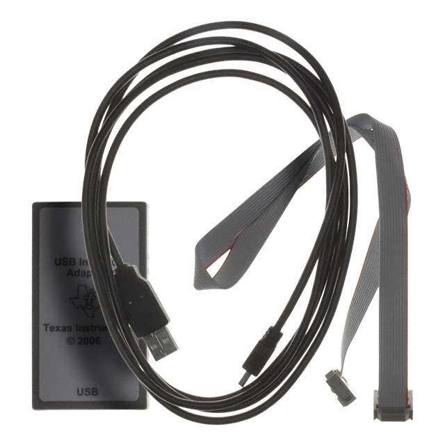
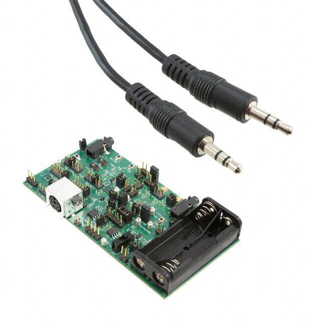
Chapter 1 SLLU093–August2006 Introduction This EVM serves as an interface adapter or a bridge between a host PC (IBM™ compatible) and one or multiple slave devices via a standard type-A to mini-B USB cable. The communication between the USB interface adapter and the host PC is via USB, while the communication between the USB interface adapter and the slave device(s) is via an inter-integrated circuit (I2C) and/or general-purpose inputs/outputs GPIOs. The bridge converts communication transactions between the USB and I2C/GPIO. Note: FortheUSBinterfaceadaptertocommunicatewithmultipleI2C slaves,buildaspecial10-pinribboncablewithmultipleconnector(s), sothatalltheI2Cslavedevicescanbedaisy-chainedtogetheron thesameribboncable. 1.1 List of Hardware Items for Operation InordertooperatethisUSBinterfaceadapter,thefollowingitemsarerequired(seeFigure1-1): • USBinterfaceadapterinanenclosure • Standardtype-Atotype-mini-B(5-pin)USBcable • 10-pinribboncablewithconnectorsonbothends USB Cable LED Indication of 10-Pin Ribbon Cable USB Attached Figure1-1.ConnectionofUSBInterfaceAdapter,USBCable,andRibbonCable SLLU093–August2006 Introduction 9 SubmitDocumentationFeedback
www.ti.com ListofSoftwareItemsforOperation 1.2 List of Software Items for Operation Inadditiontothepreviouslylistedhardwareitems,thefollowingsoftwarealsoisneeded: • I2C/GPIO/PMBUS/SMBUStransportlayerDLLdriver(PMBusTransport(USBHID).dll)createdbyTI • DemoGUIsoftware(USBSAAGUI.exe)forI2C/GPIO/PMBUS/SMBUSapplication BothcanbedownloadedfromtheTIwebsiteinthefile"USBinterfaceadapterGUI.zip",whichalso containsotheraccessoryfiles. TheUSBinterfaceadapterisrecognizedbyaPCasagenerichumaninterfacedevice(HID),whichis supportedbythebuilt-inUSB/HIDdriversoftheWindowsoperatingsystem.Therefore,itisplugandplay andnoproprietaryUSBdriverisrequired. 1.3 Step-by-Step Instructions for Operation and Troubleshooting AfteryouhavedownloadedandinstalledthetransportDLLandtheGUIdemosoftware,followthesesteps tooperatetheUSBinterfaceadapter: 1. PlugintheUSBcabletoboththePCandtheUSBinterfaceadapterandwaitforthegreenLEDto illuminate. Troubleshooting:IfthegreenLEDdoesnotilluminateafter30s,checktoensuretheUSBcableis securelyconnected.Iftheconnectionissecure,tryadifferentUSBport.IfadifferentUSBportdoes notsolvetheproblem,trytorebootthecomputer.Ifrebootingthecomputerdoesnotfixtheproblem, tryadifferentUSBcable.IftryingdifferentUSBcabledoesnotsolvetheproblem,contactTItechnical supportforhelp. 2. Pluginthe10-pinribboncabletoboththeUSBinterfaceadapterandanI2Cslaveboard.Makesure thatthenotchontheribbon-cableconnectormatchesthekeyholeofthesocketintheenclosure. 3. PoweruptheI2Cslaveboard.NotethatthedefaultI2Cspeedissetat100kHzandthedefaultpullups forI2Cdataandclocklinesaresetat2.2kW . 4. RuntheDEMOGUIsoftwareandfollowtheinstructionsfortheGUI. Troubleshooting:IftheI2CslaveboardcannottalkwiththeUSBinterfaceadapter,firstcheckto ensurethe10-pinribboncablehasbeensecurelyconnected.Iftheribboncablehasbeensecurely connected,checktheI2CcommunicationspeedandthepullupsforI2Cdataandclocklinessuitablefor theapplication.Ifnot,modifytheI2Ccommunicationspeedandthepullupsaccordingly.Ifthisstill doesnotsolvetheproblem,contactthemanufactureroftheI2Cslaveboardforhelp. 10 Introduction SLLU093–August2006 SubmitDocumentationFeedback
Chapter 2 SLLU093–August2006 Summary of Hardware Design This chapter describes the major features of hardware design for the USB interface adapter. See Chapter 6 for the schematic, bill of materials (BOM), and PCB layout information. 2.1 Introduction ThehardwareisbasedonaUSBperipheralchipfromTI(TUSB3210).TheTUSB3210hasan8052core withenhancedperformance.ThePCBisasimpletwo-layer,top-sidepopulatedboard(seetheschematic inChapter6).Themajorfeaturesofthehardwaredesignaredetailedtheinthefollowingsections. 2.2 Ribbon-Cable Connector J2 and Pinout ThisconnectorisusedforcommunicationsandcontrolsbetweentheUSBinterfaceadapterandonemore multipleI2Cslavedevice(s). Table2-1. TerminalFunctions TERMINAL I/O DESCRIPTION NAME NO. Usedaseitherthe5thPMBUSCONTROLline(output)orasGPIOpin7 PMBCTRL5/GPIO7 1 I/O (input/output,withinternalpullupenabled) Usedaseitherthe4thPMBUSCONTROLline(output)orasGPIOpin6 PMBCTRL4/GPIO6 2 I/O (input/output,withinternalpullupenabled) Usedaseitherthe3rdPMBUSCONTROLline(output)orasGPIOpin5 PMBCTRL3/GPIO5 3 I/O (input/output,withinternalpullupenabled) Usedaseitherthe2ndPMBUSCONTROLline(output)orasGPIOpin4 PMBCTRL2/GPIO4 4 I/O (input/output,withinternalpullupenabled) Thispincanprovidea3.3-Voutputpowersupplyatupto100mA.Anyslave +3.3V 5 PWR device(s)canusethispowersupplyaslongasthetotalcurrentconsumptionisless than100mA. Ground 6 GND Commongroundfortheentireevaluationboard Usedaseitherthe1stPMBUSCONTROLline(output)orasGPIOpin3 PMBCTRL1/GPIO3 7 I/O (input/output,withinternalpullupenabled) UsedaseithertheALERTline(input)forPMBUSorSMBUScommunications,oras PMBALERT/SMBALERT/GPIO2 8 I/O GPIOpin2(input/output,withinternalpullupdisabled,andwithanexternal programmablepullup) UsedaseithertheCLOCKline(output)forPMBUSorSMBUSorI2C PMBC/SMBC/SCL/GPIO1 9 I/O communications,orasGPIOpin1(input/output,withinternalpullupdisabled,and withanexternalprogrammablepullup) UsedaseithertheDATAline(input/output)forPMBUSorSMBUSorI2C PMBD/SMBD/SDA/GPIO0 10 I/O communications,orasGPIOpin0(input/output,withinternalpullupdisabled,and withanexternalprogrammablepullup) SLLU093–August2006 SummaryofHardwareDesign 11 SubmitDocumentationFeedback
www.ti.com ConfigurationofPullupResistorsforPins8,9,and10 2.3 Configuration of Pullup Resistors for Pins 8, 9, and 10 Thepullupsforpins8,9,and10(seetheschematicinChapter6)areconfigurablethrough communicationswiththeembeddedfirmwareintheTUSB3210(seethecommandSetPullupResistorsin Chapter3).Thedefaultsettingisforallthesethreepinstohavepullupsof2.2kW .Table2-2liststhe possibleoptionsforeachpin. Table2-2.ConfigurableOptionsofPullupResistorsforPins8,9,and10 PULLUPRESISTOR OPTION1 OPTION2 OPTION3 OPTION4 OPTION(BYTEVALUE) (0x00) (0x01)(DEFAULT) (0x02) (0x03) Pin8ofJ2:ALERTline Nopullup(open) 2.2kW N/A N/A Pin9ofJ2:CLOCKline Nopullup(open) 2.2kW 1kW 688W Pin10ofJ2:DATAline Nopullup(open) 2.2kW 1kW 688W 2.4 EEPROM Theembeddedfirmwareisstoredina64-KbitsEEPROM(seeU1intheschematicinChapter6).The firmwareisfieldprogrammable(seeChapter5formoreinformation).JumpershuntJ1isnormallyclosed andisusedforfirmwaredevelopmentonly.Onpowerup,theTUSB3210downloadsthefirmwareimage fromtheEEPROMtotheinternalstaticRAMandstartsfirmwareexecution(firstwithUSBenumeration) fromthere. 2.5 LED Indication of USB Attached AgreenLEDismountednexttotheUSBconnectorontheevaluationboard.EverytimetheUSBinterface adapterisattachedtoaPCviaaUSBcable,andifthehostPCdetectsitandgoesthroughUSB enumerationsuccessfully,theembeddedfirmwareilluminatesthegreenLED(D1)toindicatethat; otherwise,theLEDremainsoff.AfterunpluggingtheUSBcable,theLEDturnsoffimmediately. 12 SummaryofHardwareDesign SLLU093–August2006 SubmitDocumentationFeedback
Chapter 3 SLLU093–August2006 Firmware Programming and Communications Protocol The following sections describe the embedded firmware, as well as the communications protocol supported in the USB interface adapter and how to use each commandintheprotocol. 3.1 Firmware Features Summary TheembeddedfirmwareintheTUSB3210supportsthefollowingmajorfeatures: • Supports USB1.1 full speed at 12 Mbit/s. The USB interface adapter is recognized by the host as a generic human interface device (HID), so no proprietary USB or HID driver is needed. Therefore, the USBinterfaceadaptercanbetreatedasaUSBplug-and-playdevice. • Supports firmware programming in the external EEPROM so that firmware can be updated in the field. SeetheTIwebsite(www.ti.com)formoredetailedinformationonfirmwareprogramming. • ConfiguresdifferentpullupresistorsforALERT,DATA,andCLOCKlines • SupportsflexibleI2Creadorwritetransactions.TheUSBinterfaceadapterisusedastheI2Cmaster. • Selects different clock speeds (either 100 kHz or 400 kHz) for I2C, PMBUS, or SMBUS communications • Providesfirmwareversioninformation(seeChapter4fordetailsonfirmwareversioningscheme) 3.2 Firmware Version Command and Response USBPACKET COMMAND BYTE0 USBPACKET USBPACKET USBPACKET USBPACKET USBPACKET USBPACKET COMMENTS DESCRIPTION COMMAND BYTE1 BYTE2 BYTE3 BYTE4 BYTE5 BYTES6–63 CODE Firmware Version 0x00 SeeChapter4 (GetVersion) USBPACKET COMMAND BYTE0 USBPACKET USBPACKET USBPACKET USBPACKET USBPACKET USBPACKET COMMENTS DESCRIPTION COMMAND BYTE1 BYTE2 BYTE3 BYTE4 BYTE5 BYTES6–63 CODE Responsefrom Firmware 0x00 SeeChapter4 Version SeeChapter4foradetailedexplanationofhowtheFamilyCode,MajorVersion,andMinorVersionbytes areassigned/interpreted. SLLU093–August2006 FirmwareProgrammingandCommunicationsProtocol 13 SubmitDocumentationFeedback
www.ti.com I2CWriteCommandandResponse 3.3 I2C Write Command and Response USBPACKET COMMAND BYTE0 USBPACKET USBPACKET USBPACKET USBPACKET USBPACKET USBPACKET COMMENTS DESCRIPTION COMMAND BYTE1 BYTE2 BYTE3 BYTE4 BYTE5 BYTES6–63 CODE Cnumberofbytes(from1upto60bytes)to I2CWrite 0x14 A B C write USBPACKET COMMAND BYTE0 USBPACKET USBPACKET USBPACKET USBPACKET USBPACKET USBPACKET COMMENTS DESCRIPTION COMMAND BYTE1 BYTE2 BYTE3 BYTE4 BYTE5 BYTES6–63 CODE Responsefrom Success:0 0x94 I2CWrite Fail:1 Thefollowingdescribesthedetailedbitbankingofthiscommand:I2CStartfi writeA(=slaveaddress shiftedleftby1bit+writebitof0)fi slaveACKfi writeB(whichisusuallyeitheracommand byteoraregisteraddressbyte)fi slaveACKfi repeat(write1bytefi slaveACK)forCnumberof timesfi I2Cstop.ThereisanothermoregenericI2CWritetransactioncommandinSection3.10. 3.4 I2C Read Command and Response USBPACKET COMMAND BYTE0 USBPACKET USBPACKET USBPACKET USBPACKET USBPACKET USBPACKET COMMENTS DESCRIPTION COMMAND BYTE1 BYTE2 BYTE3 BYTE4 BYTE5 BYTES6–63 CODE D(from1to I2CRead 0x15 A B C 62bytes) USBPACKET COMMAND BYTE0 USBPACKET USBPACKET USBPACKET USBPACKET USBPACKET USBPACKET COMMENTS DESCRIPTION COMMAND BYTE1 BYTE2 BYTE3 BYTE4 BYTE5 BYTES6–63 CODE Responsefrom Success:0 0x95 Dnumberofbytesread I2CRead Fail:1 Thefollowingdescribesthedetailedbitbankingofthiscommand:I2Cstartfi writeA(=slaveaddress shiftedleftby1bit+writebitof0)fi slaveACKfi writeB(whichisusuallyeitheracommand byteoraregisteraddressbyte)fi slaveACKfi repeatedstartfi writeC(=slaveaddressshifted leftby1bit+readbitof1)fi slaveACKfi readDnumberofbytes(withmasterACKsinbetween) fromaslavefi masterNACKfi I2Cstop.ThereisanothermoregenericI2CReadtransaction commandinSection3.11. 14 FirmwareProgrammingandCommunicationsProtocol SLLU093–August2006 SubmitDocumentationFeedback
www.ti.com Read/WritePort0CommandandResponse 3.5 Read/Write Port 0 Command and Response USBPACKET COMMAND BYTE0 USBPACKET USBPACKET USBPACKET USBPACKET USBPACKET USBPACKET COMMENTS DESCRIPTION COMMAND BYTE1 BYTE2 BYTE3 BYTE4 BYTE5 BYTES6–63 CODE Bdoesnot A applytoport0 (bit.x=1for read.Each Read/Write B 0x16 read/input, GPIOcanbe Port0 (bytetowrite) bit.x=0for configuredas write/output) inputor output. USBPACKET COMMAND BYTE0 USBPACKET USBPACKET USBPACKET USBPACKET USBPACKET USBPACKET COMMENTS DESCRIPTION COMMAND BYTE1 BYTE2 BYTE3 BYTE4 BYTE5 BYTES6–63 CODE Responsefrom Success:0 Byteread Read/Write 0x96 Fail:1 fromport0 Port0 EachindividualGPIOpinoftheTUSB3210port0canbeconfiguredaseitheraninputoranoutput(see theschematicinChapter6). GPIOpins3to7areconfiguredtohaveinternalpullupsturnedonsonospecialexternalpullupsare neededunlessstrongerI/Odrivesarenecessary. GPIOpins0,1,and2areconfiguredtobeopen-drainI/Oports.Usethesoftware-configurablepullupsto supportI/Ofunctions. Whenpin0orpin1isusedasaGPIO,theI2Cdoesnotfunctionproperlyanymore.Onlyafterapower-on resetcantheI2Cfunctionbeusedagainwithoutusingpins0and1asGPIOs.Therefore,itis recommendedthatnomorethansixGPIOpinsareused,reservepins0and1exclusivelyforI2C applications. 3.6 EEPROM Program Command and Response USBPACKET COMMAND BYTE0 USBPACKET USBPACKET USBPACKET USBPACKET USBPACKET USBPACKET COMMENTS DESCRIPTION COMMAND BYTE1 BYTE2 BYTE3 BYTE4 BYTE5 BYTES6–63 CODE EEPROM A=Starting B=Starting C(#ofbytes DatatobeprogrammedintoEEPROM(upto 0x18 Program addressMSB addressLSB toprogram) 32bytes) USBPACKET COMMAND BYTE0 USBPACKET USBPACKET USBPACKET USBPACKET USBPACKET USBPACKET COMMENTS DESCRIPTION COMMAND BYTE1 BYTE2 BYTE3 BYTE4 BYTE5 BYTES6–63 CODE Responsefrom Success:0 EPROM 0x98 Fail:1 Program ThiscommandisusedforprogrammingafirmwareimagetotheEEPROM(U1onschematic)oftheEVM. Itisrecommendedthatthewholefirmwareimagebesplitintomultipleblocksof32bytesandcallthis commandrepeatedlyuntiltheprogrammingiscompleted. SLLU093–August2006 FirmwareProgrammingandCommunicationsProtocol 15 SubmitDocumentationFeedback
www.ti.com EEPROMReadCommandandResponse 3.7 EEPROM Read Command and Response USBPACKET COMMAND BYTE0 USBPACKET USBPACKET USBPACKET USBPACKET USBPACKET USBPACKET COMMENTS DESCRIPTION COMMAND BYTE1 BYTE2 BYTE3 BYTE4 BYTE5 BYTES6–63 CODE EEPROMRead 0x19 A=Starting B=Starting C(#ofbytes C£ 60 addressMSB addressLSB toread) USBPACKET COMMAND BYTE0 USBPACKET USBPACKET USBPACKET USBPACKET USBPACKET USBPACKET COMMENTS DESCRIPTION COMMAND BYTE1 BYTE2 BYTE3 BYTE4 BYTE5 BYTES6–63 CODE Responsefrom Success:0 0x99 CnumberofbytesreadbackfromEEPROM(upto32bytes) EEPROMRead Fail:1 ThiscommandworkswiththeEEPROMProgramcommandtoverifyifthefirmwareimagehasbeen programmedintotheEEPROMcorrectly.Forthebestefficiency,trytoreadablockof32bytesatatime bycallingthiscommand. 3.8 Set Pullup Resistors Command and Response USBPACKET COMMAND BYTE0 USBPACKET USBPACKET USBPACKET USBPACKET USBPACKET USBPACKET COMMENTS DESCRIPTION COMMAND BYTE1 BYTE2 BYTE3 BYTE4 BYTE5 BYTES6–63 CODE 0x00forno pullups (switchedoff), 0x01for 2.2kW ,0x02 SetPullup for1kW ,0x03 Resistors 0x1A A(forSDA) B(forSCL) C(forALERT) for688W . ForALERT, theoptionis eitheropen (0x00)or 2.2kW (0x01). USBPACKET COMMAND BYTE0 USBPACKET USBPACKET USBPACKET USBPACKET USBPACKET USBPACKET COMMENTS DESCRIPTION COMMAND BYTE1 BYTE2 BYTE3 BYTE4 BYTE5 BYTES6–63 CODE Responsefrom Pullupshave Success:0 SetPullup 0x9A been Fail:1 Resistors configured ByteAisfortheDATAlineforI2C,PMBUS,orSMBUScommunications;byteBisfortheCLOCKlinefor I2C,PMBUS,orSMBUScommunications;byteCisfortheALERTlineforPMBUScommunications.Ifa slavedevicecanprovideoneormultiplepullupresistors,switchoffthepullupsforDATA,SCL,orALERT lineaccordingly. 16 FirmwareProgrammingandCommunicationsProtocol SLLU093–August2006 SubmitDocumentationFeedback
www.ti.com SetI2C-PMBUS-SMBUSSpeedCommandandResponse 3.9 Set I2C-PMBUS-SMBUS Speed Command and Response USBPACKET COMMAND BYTE0 USBPACKET USBPACKET USBPACKET USBPACKET USBPACKET USBPACKET COMMENTS DESCRIPTION COMMAND BYTE1 BYTE2 BYTE3 BYTE4 BYTE5 BYTES6–63 CODE A(0for Set 100kHz, I2C-PMBUS- 0x1B otherwise SMBUSSpeed 400kHz) USBPACKET COMMAND BYTE0 USBPACKET USBPACKET USBPACKET USBPACKET USBPACKET USBPACKET COMMENTS DESCRIPTION COMMAND BYTE1 BYTE2 BYTE3 BYTE4 BYTE5 BYTES6–63 CODE Responsefrom Donewith Set 0x9B speed I2C-PMBUS- selection SMBUSSpeed ForI2C,PMBUS,orSMBUScommunications,theclockspeedcanbesettoeither100kHzor400kHz. AsanI2C,PMBUS,orSMBUSmaster,theUSBinterfaceadaptersupportsclockstretching(upto25ms pertransaction).Thefirmwaresetsthedefaultclockspeedto100kHz. 3.10 Generic I2C Write Command and Response USBPACKET COMMAND BYTE0 USBPACKET USBPACKET USBPACKET USBPACKET USBPACKET USBPACKET COMMENTS DESCRIPTION COMMAND BYTE1 BYTE2 BYTE3 BYTE4 BYTE5 BYTES6–63 CODE Thefirstbyte ofdatato GenericI2C writeisusually 0x1C A Anumberofbytes(from2upto62)towrite Write (device address<1+ writebitof0). USBPACKET COMMAND BYTE0 USBPACKET USBPACKET USBPACKET USBPACKET USBPACKET USBPACKET COMMENTS DESCRIPTION COMMAND BYTE1 BYTE2 BYTE3 BYTE4 BYTE5 BYTES6–63 CODE Responsefrom Success:0 GenericI2C 0x9C Fail:1 Write ThisisagenericI2CWritetransactioncommandthatcanbeappliedtomajorityofI2Capplications.The detailedbit-bankingisasfollows:I2Cstartfi repeat(write1databyte,slaveACK)forAnumberof timesfi I2Cstop. Basically,allthetransactionbytesareplacedoneafteranother,suchasaddressbyte(7-bitslaveaddress shiftedleftby1bit+writebitof0),oneormultiplecommandbytes,oneormultipledatabytesintotheA numberofbytesbufferspace,thentheUSBinterfaceadaptercarriesoutthebitbanking.Formaximum flexibility,thisgenericcommandforanyI2Cwritetransactionisrecommended. SLLU093–August2006 FirmwareProgrammingandCommunicationsProtocol 17 SubmitDocumentationFeedback
www.ti.com GenericI2CReadCommandandResponse 3.11 Generic I2C Read Command and Response USBPACKET USB USB USB USB USB COMMAND BYTE0 USBPACKET PACKET PACKET PACKET PACKET PACKET COMMENTS DESCRIPTION COMMAND BYTES6–63 BYTE1 BYTE2 BYTE3 BYTE4 BYTE5 CODE Y=1st X#of The1stbyte byteto bytes(1 ofdatato GenericI2C write+ to62)to writeisusually 0x1D A Anumberofbytes(2to60)towrite Read readbit1 readback (device USB USB address<1+ byte62 byte63 writebitof0). USBPACKET USB USB USB USB USB COMMAND BYTE0 USBPACKET PACKET PACKET PACKET PACKET PACKET COMMENTS DESCRIPTION COMMAND BYTES6-63 BYTE1 BYTE2 BYTE3 BYTE4 BYTE5 CODE Responsefrom Success:0 GenericI2C 0x9D Xnumberofbytes(1to62)readbackfromslave Fail:1 Read ThisisagenericI2CReadtransactioncommandthatcanbeappliedtomajorityofI2Capplications.The detailedbit-bankingisasfollows:I2Cstartfi repeat(write1databyte,slaveACK)forAnumberof timesfi repeatedstartfi writeYfi slaveACKfi readXnumberofbytes(withmasterACKsin between)fromaslavefi masterNACKfi I2Cstop. Basically,allthetransactionbytesareplacedoneafteranother,suchasaddressbyte(7-bitslaveaddress shiftedleftby1bit+writebitof0),oneormultiplecommandbytes,thenrepeatedstart,writeaddress byteY(7-bitslaveaddressshiftedleftby1bit+readbitof1),andreadbackxnumberofbytesfromthe slavedevicebeingaddressed.TheUSBinterfaceadaptercarriesoutthebitbanking.Formaximum flexibility,thisgenericcommandforanyI2Creadtransactionsisrecommended. 3.12 Board Test Command and Response USB PACKET USB USB USB USB USB USB COMMAND BYTE0 PACKET PACKET PACKET PACKET PACKET PACKET COMMENTS DESCRIPTION COMMAND BYTE1 BYTE2 BYTE3 BYTE4 BYTE5 BYTES6-63 CODE Starttogglingeight LEDsconnectedtothe BoardTest 0x7F eightGPIOpins simultaneouslyfor5s. USB PACKET USB USB USB USB USB USB COMMAND BYTE0 PACKET PACKET PACKET PACKET PACKET PACKET COMMENTS DESCRIPTION COMMAND BYTE1 BYTE2 BYTE3 BYTE4 BYTE5 BYTES6-63 CODE Responsefrom 0xFF Boardtestisdone BoardTest ThiscommandisforinternaltestingofUSBinterfaceadapterevaluationboardsduringproductiononly. Donotusethiscommandforanyotherapplication. 3.13 Other Commands for Different Applications ForapplicationsotherthanI2C/GPIO,suchasPMBUS,SMBUS,HDQ,etc.,seethecorresponding literatureformoredetails. 18 FirmwareProgrammingandCommunicationsProtocol SLLU093–August2006 SubmitDocumentationFeedback
Chapter 4 SLLU093–August2006 Firmware Versioning Scheme This chapter briefly describes the firmware versioning scheme for the USB interface adapter. Understanding the versioning scheme is critical for using the device in the preset configuration. This topic is important for those who would like to make a custom implementation of firmware or to understand how the firmware version is validated by thehostclientsoftware. 4.1 Introduction Thefirmwarecanbenomorethan8Kbytes.Thislimitstheamountoffunctionalitythatanysingle firmwareimagecanhave.Allthefunctionsneededforeveryapplicationcouldnotpossiblybe implementedinthisspace.Inordertomakethedeviceextensibleandtoallowitsuseinmany applications,itwasdesignedinawayforahostapplicationtoreprogramthedevicewithitsowncustom firmwarewheneverneeded. Forexample,someenddevicesmayrequireprotocolXtosendandreceivedata,butthestandard firmwaredoesnotsupportprotocolX.Inthiscase,theprogrammeroftheGUIsoftwarethatsupportsthis enddevicewritescustomfirmwarethatconformstotherulesinSection4.2.Atruntime,theGUIsoftware findstheUSBinterfaceadapterandretrievesitsfirmwareversionnumber.Iftheversionnumberisnot compatiblewiththeprotocolsneeded,theGUIsoftwarethenreprogramsthedevicewithitsownversion offirmwaresothatitcanuseit. IfallGUIsoftwarecomplieswiththisversioningsystem,thenthesamehardwarecanbereusedformany applicationswithoutinhibitingothercompliantsoftware.Thisalsoensuresthatallimplementationswill bebackwardcompatiblewitholderGUIsoftware. SLLU093–August2006 FirmwareVersioningScheme 19 SubmitDocumentationFeedback
www.ti.com RulesforImplementingCompliantCustomFirmware 4.2 Rules for Implementing Compliant Custom Firmware Inorderforcustomfirmwaretobecompatiblewiththisversioningscheme,itmustcomplywiththe followingrules: 1. ThecustomfirmwaremustsupportpairsofcommandslistedinTable4-1(seeChapter3forthe defaultimplementation). Table4-1.ListofPairsofCommandsNeededforFirmwareVersioning CODES(hex) DESCRIPTION INFORMATION 0x00and0x80 FirmwareVersion(GetVersion) RequiredtocommunicateitsuniqueidentitytotheGUIsoftware RequiredfortheGUIsoftwaretoreprogramthefirmwareonthe 0x18and0x98 EEPROMPro embeddedEEPROM RequiredfortheGUIsoftwaretovalidatethefirmwareimageonthe 0x19and0x99 EEPROMRead EEPROM 2. Thecustomfirmwaremusthaveaunique,compliantversionnumberthatdescribesitsfunctionality. Note: Together,thesetworulesdescribeaninterfacethatallGUIsoftwarecanexpecttobe implemented.IfGUIsoftwarecannotcalltheFirmwareVersioncommand,itcannot identifythefirmwareandshouldnotattempttouseitastheoutcomeisunpredictable.If GUIsoftwareneedstoreprogramtheUSBinterfaceadapter,itexpectscommand0x18to beanEEPROMprogramming.Conformingtothisstandardensuresthatthefirmware doesnotbreakthevalidationandreprogrammingcycle. 4.3 Compliant Versioning Theversioningschemeusesthreebytestomakeupauniqueidentifierthatthedevicecanreturn(asthe datapart)inresponsetotheFirmwareVersioncommand(seeChapter3formoredetails). ThefirstbyteistheFamilyCodeanditdescribeswhoisresponsibleforthefirmware.Thesecodesare givenoutinblockstovariousgroupswithTI.Forinstance,theDigitalPowerGroupownscodes01–16(or 0x01–0x10inhex).SomeFamilyCodesarereserved.Familycodes240–255(or0xF0–0xFFinhex)have beensetasideforcustomimplementationsbyendusersoranyonewantingtomakeacompliantversion ofcustomfirmwarefortheirownprivateuse. ThisFamilyCodealsodenotesthepermutationsofprotocolssupported,suchasFamilyCode1supports I2C,PMBus,andSMBus,whileFamilyCode2mightsupportI2CandProtocolX. ThesecondbyteistheMajorVersionanditdescribesarevisiontothepermutationsofprotocols.Ifthe protocolssupportedneednewfunctionalityorhavechangestothewaythattheyarecalled(signature changed)thenthisbytedenotesthechange. ThethirdbyteistheMinorVersionanditdescribesarevisiontothepermutationsofprotocols.Ifthe firmwarecodehaschangedtofixabuginthefunctionsbutnonewpublicfunctionshavebeenaddedand nochangeshavebeenmadetothefunctionsignatures,thisbyteshouldbechangedtodenotethenew version. Table4-2summarizesthesignificanceofthethree-bytecode. Table4-2.ThreeBytesforFirmwareVersioning BYTEORDER MOSTSIGNIFICANTBYTE MIDDLEBYTE LEASTSIGNIFICANTBYTE ByteMeaning FamilyCode MajorVersion MinorVersion 01=Majorrevision 01=OwnedbyDigitalPower 01=Minorrevisionofthepermutationof ExampleValue ofthepermutationof PMBus,SMBus,I2Csupported protocols protocols 20 FirmwareVersioningScheme SLLU093–August2006 SubmitDocumentationFeedback
www.ti.com CompliantVersioning Toimplementthisversioningschemeproperly,aWindows™applicationcallsaFirmwareVersion commandthat,alongwithsomeothers,isreservedandmustbepresentineachimplementationofthe device.IftheFamilyCodedoesnotmatchthecodethattheapplicationislookingfor,itshouldnot assumeanythingaboutwhatprotocolsaresupported.TheFamilyCodeshouldimmediatelyattemptto reprogramthefirmwarewithitsownversion(binaryimagedistributedwiththeapplication). AWindowsapplicationthatcorrelatesFamilyCodeandMajorVersionwiththefirmwareimplementation shouldthen,theoretically,onlyhavetocheckthattheMinorVersionisgreaterthanorequaltoitstarget MinorVersion.Afirmwareprogrammershouldbecarefultoneverremovefunctionalityfroman implementationwiththesameFamilyCode/MajorVersion,oranolderWindowsapplicationmayattempt tomakeamalformedcalltoitwhenitattemptstocommunicate.Inthecasethatsuchadrasticchangeis made,itisrecommendthatthefirmwaredeveloperchangetheFamilyCodebyte. Table4-3.InitialFamilyCodes FAMILYCODE(DECIMAL) GROUP/TEAM 00 Reserved 01–16 DigitalPower+POE 17–32 HPADesignToolsteam 33–48 BatteryManagement 49–239 Unassigned 240–255 Openforcustomimplementations(userdefined) SLLU093–August2006 FirmwareVersioningScheme 21 SubmitDocumentationFeedback
www.ti.com CompliantVersioning GUIapplicationsmayusetheflowchartinFigure4-1todeterminewhetherornottoreprogramthe firmwareontheUSBinterfaceadapter. Start Call Get Version Comand No Reprogram the USB Is first byte in response equal Interface Adapter to the required family code? with required version Yes Is second byte in response No equal to the required Major version code? Yes Is third byte greater than or No equal to the required Minor version code? Yes Use the version that already on the End board (Bugs have been fixed) Figure4-1.FlowChartforDeterminingFirmwarePrograming 22 FirmwareVersioningScheme SLLU093–August2006 SubmitDocumentationFeedback
www.ti.com CompliantVersioning Figure4-2showsanexampleofhowthefirmwareprogrammingintoEEPROMshouldfunctionbetween applications. Figure4-2.InteractionsofApplicationsDuringFirmwareProgramming SLLU093–August2006 FirmwareVersioningScheme 23 SubmitDocumentationFeedback
www.ti.com CompliantVersioning 24 FirmwareVersioningScheme SLLU093–August2006 SubmitDocumentationFeedback
Chapter 5 SLLU093–August2006 GUI and PC Libraries The adapter solution includes a set of PC libraries and a GUI that can be used to allow PCapplicationsaccesstotheadapterandtargetdevicesthattheadaptersupports. The GUI and PC libraries are designed using the Microsoft® .NET Framework, in order to leverage as many standard libraries as possible. As previously described in this document, the adapter presents itself as a USB HID to Windows. Because of this, no custom driver is required, and the application software on the PC can use the standard MicrosoftWindowsUSBdriver(usbhid.sys). Like the adapter, the Windows libraries support all the different types of device interfaces: I2C, SMBus, PMBus, and GPIO. In addition, the libraries support configuration and control of the adapter itself by allowing PC programs to update the EERPROM in the adapter, select switching in and out of resistors on data and clock lines,etc. Figure5-1representsthesoftwarearchitectureforthePCthatisused. GGUUII AApppplliiccaatitoionn:: −−VVBB ..NNEETT ssoolluuttiioonn tthhaatt uusseess DDeevviiccee TTrraannssppoorrtt ((DDLLLL)) aanndd ..NNEETT frafrmameweowrokrk −−NNoo ootthheerr ddeeppeennddeenncciieess −−SSttrriiccttllyy mmaannaaggeedd ccooddee ffoorr WWiinnddoowwss ffoorrmm ccoonnttrrooll GUI Application DDeevviiccee TTrraannssppoortr:t: −−..NNEETT DDLLLL ((mmaannaaggeedd ccooddee)) tthhaatt iiss aallssoo aa VVBB ..NNEETT ssoolluuttiioonn −−IInntteerrffaacceess wwiitthh ssttaannddaarrdd WWiinnddoowwss UUSSBB HHIIDD ddrriivveerr D..NNeEEviTTc eFF Trraarammneeswwpooorrrkkt (u(subshbihdi.ds.yssy)s) −−AAlllloowwss aabbssttrraaccttiioonn ooff aapppplliiccaattiioonn lleevveell GGUUII ffrroomm iinntteerrffaaccee aanndd cacna nb eb ere −reuusesedd i nin a anny ya apppplicliacatiotionn u usisningg t hthee a addaappteterr .NET Framework ..NNEETT FFrraammeewwoorrkk:: −−SSttaannddaarrdd iinnssttaallllaattiioonn ooff ..NNEETT ffrraammeewwoorrkk ((vveerrssiioonn 11..11)) −−IInnssttaalllleedd oonn aallll PPCCss sshhiippppiinngg wwiitthh WWiinnddoowwss ffoorr llaasstt ffeeww yyeeaarrss −−SSttaannddaarrdd lliibbrraarriieess ffoorr aapppplliiccaattiioonn ccoonnttrrooll Windows XP WWiinnddoowwss XXPP:: −−SSttaannddaarrdd iinnssttaallllaattiioonn tthhaatt sshhiippss wwiitthh PPCCss −−..NNEETT ffrraammeewwoorrkk aanndd aapppplliiccaattiioonn sshhoouulldd aallssoo wwoorrkk wwiitthh prepvreiovuiosu vse vrseirosniosn osf oWf iWndinodwosw ass a ws ewllell USB HID Driver USB HID Driver: −−SSttaannddaarrdd iinnssttaallllaattiioonn tthhaatt sshhiippss wwiitthh PPCCss Sold and supported by Microsoft −−TTaallkkss ttoo UUSSBB hhaarrddwwaarree uussiinngg WWiinnddoowwss Figure5-1.USBAdapterSoftwareArchitecture Themajorpiecesofthesoftwarearchitectureareasfollows: • WindowsXP™ • .NETFramework • Devicetransport • GUIapplication SLLU093–August2006 GUIandPCLibraries 25 SubmitDocumentationFeedback
www.ti.com WindowsXP 5.1 Windows XP WindowsXPprovidesthestandardUSBHIDsupporttotheapplication’slibrariesthroughastandardUSB HIDdriverthatcomeswithMicrosoftWindows. The.NETFrameworkisasetoflibrariesthatMicrosoftprovidesthatallowsWindowsapplicationsarich setofservicestouse.Functionalitysuchasformandwindowmanagement,memorymanagement,and databaseareallsupportedbythe.NETFramework.MostrecentapplicationswrittenforWindowsusethe .NETFramework. The.NETFrameworkistheonlydependencythatthedevicetransportlibrariesandtheGUIapplication have;therearenocustomdriversrequiredbythisapplication.The.NETFrameworkisinstalledonallnew PCs,sothereshouldbenothingtodoexceptunzipandruntheGUIapplicationthatisdeliveredforthe adapterFramework. ThecurrentversionofthedevicetransportlibrariesandGUIApplicationuseversion1.1oftheMicrosoft .NETFramework.DependingontheversionofdevelopmenttoolsusedtogenerateGUIlibrariesand applications,anupdatetothe.NETFrameworkfromMicrosoftmayberequired. TheURLtoupdatetheMicrosoft.NETFrameworkonyourPCmaybefoundatthefollowingURL: http://www.microsoft.com/downloads/details.aspx?FamilyID=0856EACB-4362-4B0D-8EDD- AAB15C5E04F5&displaylang=en 26 GUIandPCLibraries SLLU093–August2006 SubmitDocumentationFeedback
www.ti.com DeviceTransport 5.2 Device Transport Inordertoenablenewapplicationstobecreatedwithminimaleffortbyusersoftheadapter,adevice transportlibraryisprovided. Thislibraryisa.NETDLLthatwasgeneratedusingMicrosoftDeveloperStudio®2003andisbasicallya setof.NETmanagedcode.Thislibraryrequiresversion1.1ofthe.NETFrameworktobepresentonthe machinethatusesit. ThislibraryisincludedinthesampleGUIapplicationthatisprovidedwiththeadapterandisintendedto beusedbyotherapplications,aswellastomanageatargetthroughtheadapter. Tousethislibrary,simplyincludeitintheprojectbeingdevelopedasadependency. Thislibraryprovidesthefollowingfunctionality: • PrimitivesthatsupportallI/Otypesoftheadapter – I2C • I2Cread(variablelength) • I2Cwrite(variablelength) – SMBus • Receivebyte • Readbyte • Readword • Blockread • Sendbyte • Writebyte • Writeword • Blockwrite • Processcall • Blockwriteblockreadprocesscall • PECenable/disable – PMBus • Groupcommand • Assert/deassertCONTROLline • PollALERT#signal – GPIO(read/write) • Generalfunctionality – Resetadapter – Getdeviceversion – Selectinternalpullupresistors – Update/readEEPROMcontents – Select100-kHz/400-kHzbusspeed SLLU093–August2006 GUIandPCLibraries 27 SubmitDocumentationFeedback
www.ti.com GUIApplication 5.3 GUI Application Thesampleapplicationthatisavailablewiththeadapterusesthedevicetransporttocommunicatewith theadapter,aswellasthetargetdevicesbehindtheadapter.AscreenshotisshowninFigure5-2. Figure5-2.SampleGUIApplication Fromthemainmenu,updatethefirmwarefortheadapter,selectthebusspeedofthedevice(100kHzor 400kHz),andselectwhetherPECisenabledordisabledwhencommunicatingwiththedevice. Themainportionoftheformissplitintofivesections:I2C,SMBus,PMBus,GPIO,andpullupresistors. FromtheI2C,SMBus,andPMBusgroupboxes,theusercanselecteachoftheavailabletransaction typesthattheadaptersupports.Theresultofthetransactiontothedeviceisalsocommunicatedhereas anacknowledge(ACK)ornotacknowledge(NACK). IntheGPIOgroupbox,eachoftheeightGPIOpinscanbeenabledandprogrammedasreadorwrite.In addition,thestateofthepincanbereadorassertedtothedesiredvaluefromthisgroupboxaswell. Finally,theGUIallowsuserstoselectthevaluesofthepullupresistorsusedfortheSDA/SCLlines.The adapterandtheGUIallowuserstoselectfrom668W ,1.1kW ,2.2kW ,oropendrain. 28 GUIandPCLibraries SLLU093–August2006 SubmitDocumentationFeedback
Chapter 6 SLLU093–August2006 Schematic, Bill of Materials, PCB Layout This chapter contains information on schematic design, with related information on bill of materials (BOM) and printed circuit board (PCB) layout for the USB interface adapter. SLLU093–August2006 Schematic,BillofMaterials,PCBLayout 29 SubmitDocumentationFeedback
www.ti.com Schematic 6.1 Schematic Figure6-1.Schematic 30 Schematic,BillofMaterials,PCBLayout SLLU093–August2006 SubmitDocumentationFeedback
www.ti.com BillofMaterials(BOM) 6.2 Bill of Materials (BOM) Table6-1.BillofMaterials REF QTY VALUE DESCRIPTION SIZE PARTNUMBER MANUFACTURER DESIGNATOR 6 C1,C5,C6,C8, 0.1m F Capacitor,Ceramic,0.1m F,25V, 0603 C1608X7R1E104KT TDK C10,C11 X7R,10% Capacitor,Ceramic,22pF,50V, 2 C2,C3 22pF 0603 C1608C0G1H220KT TDK C0G,10% Capacitor,Ceramic,1000pF, 1 C4 1000pF 0805 Std Std 100V,C0G,5% 1 C7 1m F Capacitor,Tantalum,1m F,16V, 3216 293D105X0016A2T Vishay 20% 2 C9,C12 10m F Capacitor,Tantalum,10m F,10V, 3216 293D106X0010A2T Vishay 20% 1 D1 SSF-LXH305GD-TR Diode,LED,2.6V,25mA 0.25· 0.25 SSF-LXH305GD-TR Lumex 1 D2 MBRA130 Diode,Schottky,1A,30V SMA MBRA130 IR 1 D3 7.5V Diode,Zener,7.5V,3W SMB 1SMB5922BT3 OnSemi D4,D5,D6,D7, Diode,TVSdiode, 8 D8,D9,D10, GL05T SOT23 GL05T General LowCapacitance D11 1 J1 PTC36SAAN Header,2-pin,100milspacing, 0.1· 2 PTC36SAAN Sullins (36-pinstrip) 1 J2 86479-3 C2·o5nnpeinc,to1r0,0MmalielsRpiagchitngA,n4glWeall 0.607· 0.484 86479-3 AMP 1 J3 UX60-MB-5ST Connector,Recpt,USB-B,Mini, 0.354· 0.303 UX60-MB-5ST Hirose 5-pins,SMT Transistor,NPN,High 1 Q1 MMBT2222A SOT-23 MMBT2222A Fairchild Performance,500mA Q2,Q3,Q4, MOSFET,Pch,–50V,–0.13A, 5 Q5,Q6 BSS84 10W SOT-23 BSS84 Fairchild 3 R1,R2,R25 1.5kW Resistor,Chip,1.5kW ,1/16W, 0603 Std Std 5% 3 R17,R19,R31 2.2kW Resistor,Chip,2.2kW ,1/16W, 0603 Std Std 5% 2 R18,R20 1kW Resistor,Chip,1kW ,1/16W,5% 0603 Std Std 1 R29 200W Resistor,Chip,200W ,1/16W, 0603 Std Std 5% 1 R3 1MW Resistor,Chip,1MW ,1/16W,1% 0603 Std Std 2 R4,R28 15kW Resistor,Chip,15kW ,1/16W, 0603 Std Std 5% 5 R5,R14,R15, 100kW Resistor,Chip,100kW ,1/16W, 0603 Std Std R16,R30 5% R6,R7,R8,R9, R10,R11,R12, 14 R13,R21,R22, 33W Resistor,Chip,33W ,1/16W,5% 0603 Std Std R23,R24,R26, R27,R32 IC,SerialEEPROM64kW , 1 U1 24LC64 SO8 24LC64 Microchip 1.8Vto5.5V,400kHzMax 1 U2 TUSB3210PM IC,USB,GeneralPurpose, 0.48· 0.48 TUSB3210PM TI DeviceController IC,Micro-Power150mALDO 1 U3 TPS76333DBV SOT23-5 TPS76xxxDBV TI Regulator 1 Y1 12MHz 0.185· 0.532 CY12BPSMD Crystek RibbonCable,Socket-to-Socket, 1 M3DDA-1018J-ND 18 M3DDA-1018J-ND 3M 10pin 1 Shunt,100mil,Black 0.1 929950-00 3M PCB, 1 3.12in· 1.6in· 0.062in HPA172E2 Any SLLU093–August2006 Schematic,BillofMaterials,PCBLayout 31 SubmitDocumentationFeedback
www.ti.com BillofMaterials(BOM) Note: TheseassembliesareESDsensitive,soESDprecautionsshallbeobserved. Theseassembliesmustbecleanandfreefromfluxandallcontaminants.Useofnoclean fluxisnotacceptable. TheseassembliesmustcomplywithworkmanshipstandardsIPC-A-610Class2. Refdesignatorsmarkedwithanasterisk('**')cannotbesubstituted.Allothercomponents canbesubstitutedwithequivalentmanufacturer'scomponents. 32 Schematic,BillofMaterials,PCBLayout SLLU093–August2006 SubmitDocumentationFeedback
www.ti.com PrintedCircuitBoard(PCB)Layout 6.3 Printed Circuit Board (PCB) Layout Figure6-2throughFigure6-5showthePCBlayout. Figure6-2.PCBLayout—TopL1(CopperLayer)—AssemblyTA SLLU093–August2006 Schematic,BillofMaterials,PCBLayout 33 SubmitDocumentationFeedback
www.ti.com PrintedCircuitBoard(PCB)Layout Figure6-3.PCBLayout—TopS1(SilkscreenLayer) 34 Schematic,BillofMaterials,PCBLayout SLLU093–August2006 SubmitDocumentationFeedback
www.ti.com PrintedCircuitBoard(PCB)Layout Figure6-4.PCBLayout—TopL1(CopperLayer) SLLU093–August2006 Schematic,BillofMaterials,PCBLayout 35 SubmitDocumentationFeedback
www.ti.com PrintedCircuitBoard(PCB)Layout Figure6-5.PCBLayout—BottomL2(CopperLayer) 36 Schematic,BillofMaterials,PCBLayout SLLU093–August2006 SubmitDocumentationFeedback
Appendix A SLLU093–August2006 Lists of Communication Protocol This appendix contains a list of communication commands that can be sent from a host PC to the USB interface adapter, as well as a list of communication commands that canbesentfromtheUSBinterfaceadaptertothehostPC. A.1 Host PC to USB Interface Adapter Commands USB PACKET USB USB USB USB USB COMMAND USBPACKET BYTE0 PACKET PACKET PACKET PACKET PACKET COMMENTS DESCRIPTION BYTES6-63 COMMAND BYTE1 BYTE2 BYTE3 BYTE4 BYTE5 CODE Firmware 0x00 SeeChapter4 Version Cnumberofbytes(from1upto I2CWrite 0x14 A B C 60bytes)towrite D(from1to I2CRead 0x15 A B C 62bytes) Bdoesnot A(bit.x=1for applytoport0 Read/Write read/input, B(byteto read.Each 0x16 Port0 bit.x=0for write) GPIOcanbe write/output) configuredas inputoroutput. EEPROM A=Starting B=Starting C(#ofbytes DatatobeprogrammedintoEEPROM 0x18 Program addressMSB addressLSB toprogram) (upto32bytes) EEPROMRead 0x19 A=Starting B=Starting C(#ofbytes C£ 60 addressMSB addressLSB toprogram) 0x00forno pullups(switch off),0x01for 2.2kW ,0x02 SetPullup C(for for1kW ,0x03 Resistors 0x1A A(forSDA) B(forSCL) ALERT) for688W .For ALERT,the optioniseither open(0x00)or 2.2kW (0x01). A(0for Set 100kHz, I2C/PMBUS/SM 0x1B otherwise BUSSpeed 400kHz) Thefirstbyteof datatowriteis GenericI2C 0x1C A Anumberofbytes(from2upto62)towrite usually(device Write address<<1)+ writebit0. X#of Y=1st bytes Thefirstbyteof byteto (1to62) datatowriteis GenericI2C write+ 0x1D A Anumberofbytes(2to60)towrite toread usually(device Read readbit1 back address<<1)+ USB USB writebit0. Byte62 Byte63 SLLU093–August2006 ListsofCommunicationProtocol 37 SubmitDocumentationFeedback
www.ti.com USBInterfaceAdaptertoHostPCResponseCommands USB PACKET USB USB USB USB USB COMMAND USBPACKET BYTE0 PACKET PACKET PACKET PACKET PACKET COMMENTS DESCRIPTION BYTES6-63 COMMAND BYTE1 BYTE2 BYTE3 BYTE4 BYTE5 CODE Starttoggling eightLEDs connectedto BoardTest 0x1F theeightGPIO pins simultaneously for5s. Note: SeeChapter3fordetailedexplanationofeachcommand. A.2 USB Interface Adapter to Host PC Response Commands USBPACKET COMMAND BYTE0 USBPACKET USBPACKET USBPACKET USBPACKET USBPACKET USBPACKET COMMENTS DESCRIPTION COMMAND BYTE1 BYTE2 BYTE3 BYTE4 BYTE5 BYTES6-63 CODE Responsefrom Family Mainversion Minorversion Firmware 0x80 number (0to255) (0to255) Version (0to255) Responsefrom Success:0 0x94 I2CWrite Fail:1 Responsefrom Success:0 0x95 Dnumberofbytesread I2CRead Fail:1 Responsefrom Success:0 Byteread Read/Write 0x96 Fail:1 fromport0 Port0 Responsefrom Success:0 EEPROM 0x98 Fail:1 Program Responsefrom Success:0 0x99 CnumberofbytesreadbackfromEEPROM(upto32bytes) EEPROMRead Fail:1 Responsefrom Success:0 Pullupshave SetPullup 0x9A Fail:1 beenset. Resistors Responsefrom Donewith Set 0x9B speed I2C/PMBUS/SM selection. BUSSpeed Responsefrom Success:0 GenericI2C 0x9C Fail:1 Write Responsefrom Success:0 GenericI2C 0x9D Xnumberofbytes(1to62)readbackfromslave Fail:1 Read Responsefrom Boardtestis 0xFF BoardTest done. Note: SeeChapter3fordetailedexplanationofeachcommand. 38 ListsofCommunicationProtocol SLLU093–August2006 SubmitDocumentationFeedback
Appendix B SLLU093–August2006 PMBUS/SMBUS Communications This appendix describes the support for USB-to-PMBUS/SMBUS communications in theUSBInterfaceAdapterandhowtouseitforyourapplications. B.1 Overview ThedefaultfirmwareforUSBInterfaceAdapterprovidessupportforUSBtoPMBUS(revision1.0)and SMBUS(revision2.0)communications.SimilartoitsI2Capplication,theUSBInterfaceAdapteractsasa PMBUS/SMBUSmaster,whichcantalkwithoneormultiplePMBUS/SMBUSslavedevicesdaisy-chained toa10-pinribboncable. B.2 Basic SMBUS Transaction Types Supported BecausePMBUScommunicationisderivedfromSMBUScommunication,theysharebasicSMBUS transactiontypesincommon.ThesebasicSMBUStransactiontypesinclude: • Sendbyte • Receivebyte • Writebyte • Readbyte • Writeword • Readword • Blockwrite • Blockread • Processcall • Blockread–blockwriteprocesscall Inaddition,PMBUScommunicationalsosupportsGroupcommand. AllthesecommandsareimplementedintheUSBInterfaceAdapterfirmware. B.3 Special Signals Used for PMBUS/SMBUS Communications RefertoTable2-2forspecialsignallinesusedforPMBUS/SMBUScommunications. Specifically,aslavedevicecanassertanALERTsignal(bypullingitlow)toreportafaultorawarning conditiontotheUSBInterfaceAdapter;thehostPCcanobtaintheALERTsignalbypollingtheUSB InterfaceAdapter.NotethattheUSBInterfaceAdapterdoesnotsupportanyHostNotifyProtocol.This meansthattheUSBInterfaceAdaptercannotbecomeaPMBUS/SMBUSslaveand,therefore,cannot supportaslavetotemporarilybecomeamasterandnotifythehostaboutthefaultorthewarning condition. ForPMBUScommunications,theUSBInterfaceAdapterprovidesfiveCONTROLsignals,eachofwhich canbeusedtoenable/disablethepoweringupofoneormultipleslavedevice(s). WriteProtectsignalisnotsupported;neitheristheRESETsignal. SLLU093–August2006 PMBUS/SMBUSCommunications 39 SubmitDocumentationFeedback
www.ti.com PacketErrorChecking(PEC)Implementation B.4 Packet Error Checking (PEC) Implementation Bydefault,theUSBInterfaceAdapterfirmwareimplementsPECforallthedifferentcommands.However, theimplementationofPECbyteisoptional.ThereisaspecialhostPCtoUSBInterfaceAdapter commandthatcanbeusedtoturnPEConoroff(seeSectionB.23). IfPECisonorenabled,thefirmwareintheUSBInterfaceAdaptereitherappendsaPECbytetoa commandsenttooneormultipleslavedevicesorchecksthevalidityofaPECbytereceivedfromaslave device. B.5 Communication Clock Speed and Clock Stretching Thedefaultclockspeedis100kHz,whichiscompatiblewithPMBUS1.0andSMBUS2.0.For compatibilitywithfuturePMBUSspecs,theclockspeedcanbeincreasedto400kHz(seeSection3.9). ForeachPMBUS/SMBUStransaction,theaccumulativetimeofclockstretchingcannotbemore25ms. B.6 Configuration of Pullup Resistors for ALERT, DATA, and CLOCK Lines RefertoSection3.8formoredetailsonthistopic. B.7 Limitations BecauseofthelimitedcapabilitiesoftheTUSB3210USBperipheralchip,theUSBInterfaceAdapterhas thefollowinglimitations: • ExtendedCommandisnotsupported.Onlythefirst256commandsaresupported. • Foranyblockwriteorblockreadcommand,thenumberofdatabytesislimitedto32bytesonly,even thoughthePMBUSspecssupportupto256bytesofdatapertransaction. • AddressResolutionProtocol(ARP)isnotsupported,sonomultiplemastersareallowed. • HostNotifyProtocolisnotsupported(seeSectionB.3). 40 PMBUS/SMBUSCommunications SLLU093–August2006 SubmitDocumentationFeedback
www.ti.com ListofHostPCtoUSBInterfaceAdapterCommands B.8 List of Host PC to USB Interface Adapter Commands TableB-1.HostPCtoUSBInterfaceAdapterCommands USBPACKET COMMAND BYTE0 USBPACKET USBPACKET USBPACKET USBPACKET USBPACKET USBPACKET COMMENTS DESCRIPTION COMMAND BYTE1 BYTE2 BYTE3 BYTE4 BYTE5 BYTES6–63 CODE SendByte 0x01 A B ReceiveByte 0x02 A WriteByte 0x03 A B C WriteWord 0x04 A B C D ReadByte 0x05 A B C ReadWord 0x06 A B C ProcessCall 0x07 A B C D E BlockWrite 0x08 A B C Cnumberofbytes(from1to32bytes)towrite BlockRead 0x09 A B C BlockRead– Cnumberofbytes(from1to BlockWrite 0x0A A B C D 31bytes)towrite ProcessCall Write0toDif Group D(0xFFfor Cnumberofbytes(from1to 0x0B A B C notforthelast Command lastpacket) 32bytes)towrite packet Bitlogic1for Assert\Deassert Bit0forline1, assert,bit CONTROL 0x0C ..., logic0for Lines bit4forline5 deassert PollPMBUS 0x0F SignalLines TurnOn/Off 0foroff, 0x11 PEC otherwiseon SLLU093–August2006 PMBUS/SMBUSCommunications 41 SubmitDocumentationFeedback
www.ti.com ListofUSBInterfaceAdaptertoHostPCResponseCommands B.9 List of USB Interface Adapter to Host PC Response Commands TableB-2.USBInterfaceAdaptertoHostPCResponseCommands USBPACKET COMMAND BYTE0 USBPACKET USBPACKET USBPACKET USBPACKET USBPACKET USBPACKET COMMENTS DESCRIPTION COMMAND BYTE1 BYTE2 BYTE3 BYTE4 BYTE5 BYTES6–63 CODE Responsefrom Success:0 0x81 SendByte Fail:1 Responsefrom Success:0 Byteread 0x82 ReceiveByte Fail:1 fromslave Responsefrom Success:0 0x83 WriteByte Fail:1 Responsefrom Success:0 0x84 WriteWord Fail:1 Responsefrom Success:0 Byteread 0x85 ReadByte Fail:1 fromslave Lowbyteof Highbyteof Responsefrom Success:0 0x86 wordread wordread ReadWord Fail:1 fromslave fromslave Lowbyteof Highbyteof Responsefrom Success:0 0x87 wordread wordread ProcessCall Fail:1 fromslave fromslave Responsefrom Success:0 0x88 BlockWrite Fail:1 Responsefrom Success:0 0x89 X Xnumberofbytesreadfromslave(upto32bytes) BlockRead Fail:1 Responsefrom BlockRead– Success:0 0x8A X Xnumberofbytesreadfromslave(upto31bytes) BlockWrite Fail:1 ProcessCall Responsefrom Success:0 Group 0x8B Fail:1 Command Responsefrom Assert/Deassert Success:0 0x8C CONTROL Fail:1 Lines Bit0for CONTROL1, …, Responsefrom bit4for Logichighfor PollPMBUS 0x8F CONTROL5, 1,logiclowfor SignalLines bit5for 0 ALERT, bits6and7 notused Responsefrom Success:0 TurnOn/Off 0x91 Fail:1 PEC Seethefollowingsectionsfordetailedexplanationofeachcommand. 42 PMBUS/SMBUSCommunications SLLU093–August2006 SubmitDocumentationFeedback
www.ti.com SendByteCommandandResponse B.10 Send Byte Command and Response USBPACKET COMMAND BYTE0 USBPACKET USBPACKET USBPACKET USBPACKET USBPACKET USBPACKET COMMENTS DESCRIPTION COMMAND BYTE1 BYTE2 BYTE3 BYTE4 BYTE5 BYTES6–63 CODE SendByte 0x01 A B USBPACKET COMMAND BYTE0 USBPACKET USBPACKET USBPACKET USBPACKET USBPACKET USBPACKET COMMENTS DESCRIPTION COMMAND BYTE1 BYTE2 BYTE3 BYTE4 BYTE5 BYTES6–63 CODE Responsefrom Success:0 0x81 SendByte Fail:1 ThefollowingdescribesthedetailedbitbankingoftheSendBytecommand(withPECon): PMBUS/SMBUSstartfi writeA(=slaveaddressshiftedleftby1bit+writebitof0)fi slaveACK fi writeB(acommandbytedefinedbyPMBUSorSMBUS)fi slaveACKfi writePECbytefi slave ACKfi PMBUS/SMBUSstop B.11 Receive Byte Command and Response USBPACKET COMMAND BYTE0 USBPACKET USBPACKET USBPACKET USBPACKET USBPACKET USBPACKET COMMENTS DESCRIPTION COMMAND BYTE1 BYTE2 BYTE3 BYTE4 BYTE5 BYTES6–63 CODE ReceiveByte 0x02 A USBPACKET COMMAND BYTE0 USBPACKET USBPACKET USBPACKET USBPACKET USBPACKET USBPACKET COMMENTS DESCRIPTION COMMAND BYTE1 BYTE2 BYTE3 BYTE4 BYTE5 BYTES6–63 CODE Responsefrom Success:0 Byteread 0x82 ReceiveByte Fail:1 fromslave ThefollowingdescribesthedetailedbitbankingoftheReceiveBytecommand(withPECon): PMBUS/SMBUSstartfi writeA(=slaveaddressshiftedleftby1bit+readbitof1)fi slaveACKfi readin1databytefromslavefi masterACKfi readinPECbytefromslavefi masterNACKfi PMBUS/SMBUSstop B.12 Write Byte Command and Response USBPACKET COMMAND BYTE0 USBPACKET USBPACKET USBPACKET USBPACKET USBPACKET USBPACKET COMMENTS DESCRIPTION COMMAND BYTE1 BYTE2 BYTE3 BYTE4 BYTE5 BYTES6–63 CODE WriteByte 0x03 A B C USBPACKET COMMAND BYTE0 USBPACKET USBPACKET USBPACKET USBPACKET USBPACKET USBPACKET COMMENTS DESCRIPTION COMMAND BYTE1 BYTE2 BYTE3 BYTE4 BYTE5 BYTES6–63 CODE Responsefrom Success:0 0x83 WriteByte Fail:1 ThefollowingdescribesthedetailedbitbankingoftheWriteBytecommand(withPECon): PMBUS/SMBUSstartfi writeA(=slaveaddressshiftedleftby1bit+writebitof0)fi slaveACK fi writeB(acommandbytedefinedbyPMBUSorSMBUS)fi slaveACKfi writeC(adatabyte)fi slaveACKfi writePECbytefi slaveACKfi PMBUS/SMBUSstop SLLU093–August2006 PMBUS/SMBUSCommunications 43 SubmitDocumentationFeedback
www.ti.com WriteWordCommandandResponse B.13 Write Word Command and Response USBPACKET COMMAND BYTE0 USBPACKET USBPACKET USBPACKET USBPACKET USBPACKET USBPACKET COMMENTS DESCRIPTION COMMAND BYTE1 BYTE2 BYTE3 BYTE4 BYTE5 BYTES6–63 CODE WriteWord 0x04 A B C D USBPACKET COMMAND BYTE0 USBPACKET USBPACKET USBPACKET USBPACKET USBPACKET USBPACKET COMMENTS DESCRIPTION COMMAND BYTE1 BYTE2 BYTE3 BYTE4 BYTE5 BYTES6–63 CODE Responsefrom Success:0 0x84 WriteWord Fail:1 ThefollowingdescribesthedetailedbitbankingoftheWriteWordcommand(withPECon): PMBUS/SMBUSstartfi writeA(=slaveaddressshiftedleftby1bit+writebitof0)fi slaveACK fi writeB(acommandbytedefinedbyPMBUSorSMBUS)fi slaveACKfi writeC(lowbyteofa dataword)fi slaveACKfi writeD(highbyteofthedataword)fi slaveACKfi writePECbytefi slaveACKfi PMBUS/SMBUSstop B.14 Read Byte Command and Response USBPACKET COMMAND BYTE0 USBPACKET USBPACKET USBPACKET USBPACKET USBPACKET USBPACKET COMMENTS DESCRIPTION COMMAND BYTE1 BYTE2 BYTE3 BYTE4 BYTE5 BYTES6–63 CODE ReadByte 0x05 A B C USBPACKET COMMAND BYTE0 USBPACKET USBPACKET USBPACKET USBPACKET USBPACKET USBPACKET COMMENTS DESCRIPTION COMMAND BYTE1 BYTE2 BYTE3 BYTE4 BYTE5 BYTES6–63 CODE Responsefrom Success:0 Byteread 0x85 ReadByte Fail:1 fromslave ThefollowingdescribesthedetailedbitbankingoftheReadBytecommand(withPECon): PMBUS/SMBUSstartfi writeA(=slaveaddressshiftedleftby1bit+writebitof0)fi slaveACK fi writeB(acommandbytedefinedbyPMBUSorSMBUS)fi slaveACKfi repeatedstartfi write C(=slaveaddressshiftedleftby1bit+readbitof1)fi slaveACKfi readin1databytefrom slavefi masterACKfi readinPECbytefromslavefi masterNACKfi PMBUS/SMBUSstop 44 PMBUS/SMBUSCommunications SLLU093–August2006 SubmitDocumentationFeedback
www.ti.com ReadWordCommandandResponse B.15 Read Word Command and Response USBPACKET COMMAND BYTE0 USBPACKET USBPACKET USBPACKET USBPACKET USBPACKET USBPACKET COMMENTS DESCRIPTION COMMAND BYTE1 BYTE2 BYTE3 BYTE4 BYTE5 BYTES6–63 CODE ReadWord 0x06 A B C USBPACKET COMMAND BYTE0 USBPACKET USBPACKET USBPACKET USBPACKET USBPACKET USBPACKET COMMENTS DESCRIPTION COMMAND BYTE1 BYTE2 BYTE3 BYTE4 BYTE5 BYTES6–63 CODE Lowbyteof Highbyteof Responsefrom Success:0 0x86 wordread wordread ReadWord Fail:1 fromslave fromslave ThefollowingdescribesthedetailedbitbankingoftheReadWordcommand(withPECon): PMBUS/SMBUSstartfi writeA(=slaveaddressshiftedleftby1bit+writebitof0)fi slaveACK fi writeB(acommandbytedefinedbyPMBUSorSMBUS)fi slaveACKfi repeatedstartfi write C(=slaveaddressshiftedleftby1bit+readbitof1)fi slaveACKfi readinthelowbyteofadata wordfromslavefi masterACKfi readinthehighbyteofthedatawordfromslavefi masterACK fi readinPECbytefromslavefi masterNACKfi PMBUS/SMBUSstop B.16 Process Call Command and Response USBPACKET COMMAND BYTE0 USBPACKET USBPACKET USBPACKET USBPACKET USBPACKET USBPACKET COMMENTS DESCRIPTION COMMAND BYTE1 BYTE2 BYTE3 BYTE4 BYTE5 BYTES6–63 CODE ProcessCall 0x07 A B C D E USBPACKET COMMAND BYTE0 USBPACKET USBPACKET USBPACKET USBPACKET USBPACKET USBPACKET COMMENTS DESCRIPTION COMMAND BYTE1 BYTE2 BYTE3 BYTE4 BYTE5 BYTES6–63 CODE Lowbyteof Highbyteof Responsefrom Success:0 0x87 wordread wordread ProcessCall Fail:1 fromslave fromslave ThefollowingdescribesthedetailedbitbankingoftheProcessCallcommand(withPECon): PMBUS/SMBUSstartfi writeA(=slaveaddressshiftedleftby1bit+writebitof0)fi slaveACK fi writeB(acommandbytedefinedbyPMBUSorSMBUS)fi slaveACKfi writeC(lowbyteofa dataword)fi slaveACKfi writeD(highbyteofthedataword)fi slaveACKfi repeatedstartfi writeE(=slaveaddressshiftedleftby1bit+readbitof1)fi slaveACKfi readinthelowbyteof adatawordfromslavefi masterACKfi readinthehighbyteofthedatawordfromslavefi masterACKfi readinPECbytefromslavefi masterNACKfi PMBUS/SMBUSstop SLLU093–August2006 PMBUS/SMBUSCommunications 45 SubmitDocumentationFeedback
www.ti.com BlockWriteCommandandResponse B.17 Block Write Command and Response USBPACKET COMMAND BYTE0 USBPACKET USBPACKET USBPACKET USBPACKET USBPACKET USBPACKET COMMENTS DESCRIPTION COMMAND BYTE1 BYTE2 BYTE3 BYTE4 BYTE5 BYTES6–63 CODE Cnumberofbytes(from1upto32bytes)to BlockWrite 0x08 A B C write USBPACKET COMMAND BYTE0 USBPACKET USBPACKET USBPACKET USBPACKET USBPACKET USBPACKET COMMENTS DESCRIPTION COMMAND BYTE1 BYTE2 BYTE3 BYTE4 BYTE5 BYTES6–63 CODE Responsefrom Success:0 0x88 BlockWrite Fail:1 ThefollowingdescribesthedetailedbitbankingoftheBlockWritecommand(withPECon): PMBUS/SMBUSstartfi writeA(=slaveaddressshiftedleftby1bit+writebitof0)fi slaveACK fi writeB(acommandbytedefinedbyPMBUSorSMBUS)fi slaveACKfi writeC(numberof bytestowritetoslave)fi slaveACKfi repeat(writenextbytefi slaveACK)forCnumberoftimes fi writePECbytefi slaveACKfi PMBUS/SMBUSstop B.18 Block Read Command and Response USBPACKET COMMAND BYTE0 USBPACKET USBPACKET USBPACKET USBPACKET USBPACKET USBPACKET COMMENTS DESCRIPTION COMMAND BYTE1 BYTE2 BYTE3 BYTE4 BYTE5 BYTES6–63 CODE BlockRead 0x09 A B C USBPACKET COMMAND BYTE0 USBPACKET USBPACKET USBPACKET USBPACKET USBPACKET USBPACKET COMMENTS DESCRIPTION COMMAND BYTE1 BYTE2 BYTE3 BYTE4 BYTE5 BYTES6–63 CODE Responsefrom Success:0 0x89 X Xnumberofbytesreadfromslave(upto32bytes) BlockRead Fail:1 ThefollowingdescribesthedetailedbitbankingoftheBlockReadcommand(withPECon): PMBUS/SMBUSstartfi writeA(=slaveaddressshiftedleftby1bit+writebitof0)fi slaveACK fi writeB(acommandbytedefinedbyPMBUSorSMBUS)fi slaveACKfi repeatedstartfi write C(=slaveaddressshiftedleftby1bit+readbitof1)fi slaveACKfi readinX(numberofdata bytestoreadfromslave)fi masterACKfi repeat(readinnextbytefi masterACK)forXnumber oftimesfi readinPECbytefromslavefi masterNACKfi PMBUS/SMBUSstop 46 PMBUS/SMBUSCommunications SLLU093–August2006 SubmitDocumentationFeedback
www.ti.com BlockRead–BlockWriteProcessCallCommandandResponse B.19 Block Read – Block Write Process Call Command and Response USBPACKET COMMAND BYTE0 USBPACKET USBPACKET USBPACKET USBPACKET USBPACKET USBPACKET COMMENTS DESCRIPTION COMMAND BYTE1 BYTE2 BYTE3 BYTE4 BYTE5 BYTES6–63 CODE BlockRead– Cnumberofbytes(from1up BlockWrite 0x0A A B C D to31bytes)towrite ProcessCall USBPACKET COMMAND BYTE0 USBPACKET USBPACKET USBPACKET USBPACKET USBPACKET USBPACKET COMMENTS DESCRIPTION COMMAND BYTE1 BYTE2 BYTE3 BYTE4 BYTE5 BYTES6–63 CODE Responsefrom BlockRead– Success:0 0x8A X Xnumberofbytesreadfromslave(upto31bytes) BlockWrite Fail:1 ProcessCall ThefollowingdescribesthedetailedbitbankingoftheBlockRead–BlockWriteProcessCallcommand (withPECon): PMBUS/SMBUSstartfi writeA(=slaveaddressshiftedleftby1bit+writebitof0)fi slaveACK fi writeB(acommandbytedefinedbyPMBUSorSMBUS)fi slaveACKfi writeC(numberofdata bytestowrite)fi slaveACKfi repeat(writenextdatabytefi slaveACK)forCnumberoftimesfi repeatedstartfi writeD(=slaveaddressshiftedleftby1bit+readbitof1)fi slaveACKfi read inX(numberofdatabytestoreadfromslave)fi masterACKfi repeat(readinnextbytefi masterACK)forXnumberoftimesfi readinPECbytefromslavefi masterNACKfi PMBUS/SMBUSstop B.20 Group Command and Response USBPACKET COMMAND BYTE0 USBPACKET USBPACKET USBPACKET USBPACKET USBPACKET USBPACKET COMMENTS DESCRIPTION COMMAND BYTE1 BYTE2 BYTE3 BYTE4 BYTE5 BYTES6–63 CODE Write0toDif Group D(0xFFfor Cnumberofbytes(from1up 0x0B A B C notforthelast Command lastpacket) to32bytes)towrite packet USBPACKET COMMAND BYTE0 USBPACKET USBPACKET USBPACKET USBPACKET USBPACKET USBPACKET COMMENTS DESCRIPTION COMMAND BYTE1 BYTE2 BYTE3 BYTE4 BYTE5 BYTES6–63 CODE Responsefrom Success:0 Group 0x8B Fail:1 Command ThefollowingdescribesthedetailedbitbankingoftheGroupcommand(withPECon): PMBUS/SMBUSstartfi writeA(=slaveaddressshiftedleftby1bit+writebitof0)fi slaveACK fi writeB(acommandbytedefinedbyPMBUSorSMBUS)fi slaveACKfi writeC(numberof bytestowritetoslave)fi slaveACKfi repeat(writenextbytefi slaveACK)forCnumberoftimes fi writePECbytefi slaveACKfi ifbyteD=0xFF,then(PMBUS/SMBUSstop);otherwise,waitto receivethenextUSBpacketformorewritingtoslave(s) SLLU093–August2006 PMBUS/SMBUSCommunications 47 SubmitDocumentationFeedback
www.ti.com Assert/DeassertCONTROLLinesCommandandResponse B.21 Assert/Deassert CONTROL Lines Command and Response USBPACKET COMMAND BYTE0 USBPACKET USBPACKET USBPACKET USBPACKET USBPACKET USBPACKET COMMENTS DESCRIPTION COMMAND BYTE1 BYTE2 BYTE3 BYTE4 BYTE5 BYTES6–63 CODE Bitlogic1for Assert/Deassert Bit0forline1, CONTROL 0x0C …, assert, bitlogic0for Lines bit4forline5 deassert USBPACKET COMMAND BYTE0 USBPACKET USBPACKET USBPACKET USBPACKET USBPACKET USBPACKET COMMENTS DESCRIPTION COMMAND BYTE1 BYTE2 BYTE3 BYTE4 BYTE5 BYTES6–63 CODE Responsefrom Assert/Deassert Success:0 0x8C CONTROL Fail:1 Lines EachCONTROLlinecanbeusedtoenable/disablethepoweringupofoneofmultipleslaves. B.22 Poll PMBUS Signal Lines Command and Response USBPACKET COMMAND BYTE0 USBPACKET USBPACKET USBPACKET USBPACKET USBPACKET USBPACKET COMMENTS DESCRIPTION COMMAND BYTE1 BYTE2 BYTE3 BYTE4 BYTE5 BYTES6–63 CODE PollPUMBUS 0x0F SignalLines USBPACKET COMMAND BYTE0 USBPACKET USBPACKET USBPACKET USBPACKET USBPACKET USBPACKET COMMENTS DESCRIPTION COMMAND BYTE1 BYTE2 BYTE3 BYTE4 BYTE5 BYTES6–63 CODE Bit0for CONTROL1, …, Responsefrom bit4for Logichighfor PollPMBUS 0x8F CONTROL5, 1,logiclowfor SignalLines bit5for 0 ALERT, bits6and7 notused NotethatthereiscurrentlynosupportforRESETsignalorWRITE_PROTECTsignal. 48 PMBUS/SMBUSCommunications SLLU093–August2006 SubmitDocumentationFeedback
www.ti.com TurnOn/OffPECCommandandResponse B.23 Turn On/Off PEC Command and Response USBPACKET COMMAND BYTE0 USBPACKET USBPACKET USBPACKET USBPACKET USBPACKET USBPACKET COMMENTS DESCRIPTION COMMAND BYTE1 BYTE2 BYTE3 BYTE4 BYTE5 BYTES6–63 CODE TurnOn/Off 0foroff, 0x11 PEC otherwiseon USBPACKET COMMAND BYTE0 USBPACKET USBPACKET USBPACKET USBPACKET USBPACKET USBPACKET COMMENTS DESCRIPTION COMMAND BYTE1 BYTE2 BYTE3 BYTE4 BYTE5 BYTES6–63 CODE Responsefrom Success:0 TurnOn/Off 0x91 Fail:1 PEC ThedefaultisPECon.Fordataintegrityandhencepower-systemreliabilityduringPMBUS/SMBUS communicationsinswitchingpowerenvironments,TIstronglyrecommendstheadoptionofPECbytefor everyPMBUS/SMBUScommunicationtransaction. SLLU093–August2006 PMBUS/SMBUSCommunications 49 SubmitDocumentationFeedback
IMPORTANT NOTICE Texas Instruments Incorporated and its subsidiaries (TI) reserve the right to make corrections, modifications, enhancements, improvements, and other changes to its products and services at any time and to discontinue any product or service without notice. Customers should obtain the latest relevant information before placing orders and should verify that such information is current and complete. All products are sold subject to TI’s terms and conditions of sale supplied at the time of order acknowledgment. TI warrants performance of its hardware products to the specifications applicable at the time of sale in accordance with TI’s standard warranty. Testing and other quality control techniques are used to the extent TI deems necessary to support this warranty. Except where mandated by government requirements, testing of all parameters of each product is not necessarily performed. TI assumes no liability for applications assistance or customer product design. Customers are responsible for their products and applications using TI components. To minimize the risks associated with customer products and applications, customers should provide adequate design and operating safeguards. TI does not warrant or represent that any license, either express or implied, is granted under any TI patent right, copyright, mask work right, or other TI intellectual property right relating to any combination, machine, or process in which TI products or services are used. Information published by TI regarding third-party products or services does not constitute a license from TI to use such products or services or a warranty or endorsement thereof. Use of such information may require a license from a third party under the patents or other intellectual property of the third party, or a license from TI under the patents or other intellectual property of TI. Reproduction of information in TI data books or data sheets is permissible only if reproduction is without alteration and is accompanied by all associated warranties, conditions, limitations, and notices. Reproduction of this information with alteration is an unfair and deceptive business practice. TI is not responsible or liable for such altered documentation. Resale of TI products or services with statements different from or beyond the parameters stated by TI for that product or service voids all express and any implied warranties for the associated TI product or service and is an unfair and deceptive business practice. TI is not responsible or liable for any such statements. Following are URLs where you can obtain information on other Texas Instruments products and application solutions: Products Applications Amplifiers amplifier.ti.com Audio www.ti.com/audio Data Converters dataconverter.ti.com Automotive www.ti.com/automotive DSP dsp.ti.com Broadband www.ti.com/broadband Interface interface.ti.com Digital Control www.ti.com/digitalcontrol Logic logic.ti.com Military www.ti.com/military Power Mgmt power.ti.com Optical Networking www.ti.com/opticalnetwork Microcontrollers microcontroller.ti.com Security www.ti.com/security Low Power Wireless www.ti.com/lpw Telephony www.ti.com/telephony Video & Imaging www.ti.com/video Wireless www.ti.com/wireless Mailing Address: Texas Instruments Post Office Box 655303 Dallas, Texas 75265 Copyright 2006, Texas Instruments Incorporated