ICGOO在线商城 > 集成电路(IC) > PMIC - 栅极驱动器 > UCC27531DBVR
 Datasheet下载
- 型号: UCC27531DBVR
- 制造商: Texas Instruments
- 库位|库存: xxxx|xxxx
- 要求:
| 数量阶梯 | 香港交货 | 国内含税 |
| +xxxx | $xxxx | ¥xxxx |
查看当月历史价格
查看今年历史价格
UCC27531DBVR产品简介:
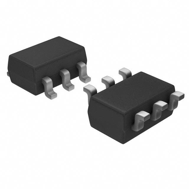
ICGOO电子元器件商城为您提供UCC27531DBVR由Texas Instruments设计生产,在icgoo商城现货销售,并且可以通过原厂、代理商等渠道进行代购。 UCC27531DBVR价格参考。Texas InstrumentsUCC27531DBVR封装/规格:PMIC - 栅极驱动器, Low-Side Gate Driver IC Non-Inverting SOT-23-6。您可以下载UCC27531DBVR参考资料、Datasheet数据手册功能说明书,资料中有UCC27531DBVR 详细功能的应用电路图电压和使用方法及教程。
UCC27531DBVR是Texas Instruments(德州仪器)推出的一款高性能单通道栅极驱动器,属于PMIC - 栅极驱动器类别。该器件广泛应用于需要高效、可靠驱动功率MOSFET或IGBT的场景。

其典型应用场景包括:开关电源(SMPS),如AC-DC和DC-DC转换器,用于服务器、通信设备和工业电源系统;电机驱动系统,例如在工业自动化、电动工具和家用电器中驱动直流或无刷直流电机;以及LED照明驱动电源,提供稳定高效的开关控制。此外,UCC27531DBVR也适用于光伏逆变器、UPS(不间断电源)和电动汽车充电系统等新能源领域。

该芯片具有高达4A的峰值输出电流,支持快速上升/下降时间,可有效减少开关损耗;具备宽输入电压范围(3V至18V),兼容数字和模拟控制器输出;内置欠压锁定(UVLO)保护功能,提升系统可靠性。SOT-23-6小型封装使其适用于空间受限的高密度电路设计。

综上,UCC27531DBVR凭借其高驱动能力、优良的抗噪声性能和紧凑封装,成为工业、通信和能源等领域中功率开关驱动的理想选择。
| 参数 | 数值 |
| 产品目录 | 集成电路 (IC)半导体 |
| 描述 | IC GATE DRVR IGBT/MOSFET SOT23-6门驱动器 2.5-5A 35VMX VDD FET & IGBT Sgl Gate Dvr |
| DevelopmentKit | UCC27531EVM-184 |
| 产品分类 | PMIC - MOSFET,电桥驱动器 - 外部开关集成电路 - IC |
| 品牌 | Texas Instruments |
| 产品手册 | |
| 产品图片 |
|
| rohs | 符合RoHS无铅 / 符合限制有害物质指令(RoHS)规范要求 |
| 产品系列 | 电源管理 IC,门驱动器,Texas Instruments UCC27531DBVR- |
| 数据手册 | |
| 产品型号 | UCC27531DBVR |
| PCN组件/产地 | |
| 上升时间 | 15 ns |
| 下降时间 | 7 ns |
| 产品 | Driver ICs - Various |
| 产品种类 | 门驱动器 |
| 供应商器件封装 | SOT-23-6 |
| 其它名称 | 296-35581-2 |
| 包装 | 带卷 (TR) |
| 商标 | Texas Instruments |
| 安装类型 | 表面贴装 |
| 安装风格 | SMD/SMT |
| 封装 | Reel |
| 封装/外壳 | SOT-23-6 |
| 封装/箱体 | SOT-23-6 |
| 工作温度 | -40°C ~ 140°C |
| 工厂包装数量 | 3000 |
| 延迟时间 | 17ns |
| 最大工作温度 | + 140 C |
| 最大开启延迟时间 | 26 ns |
| 最小工作温度 | - 40 C |
| 标准包装 | 3,000 |
| 激励器数量 | 1 Driver |
| 电压-电源 | 10 V ~ 32 V |
| 电流-峰值 | 2.5A, 5A |
| 电源电压-最大 | 35 V |
| 电源电压-最小 | 10 V |
| 空闲时间—最大值 | 17 ns |
| 类型 | FET and IGBT Single-Gate Driver |
| 系列 | UCC27531 |
| 输入类型 | 非反相 |
| 输出数 | 1 |
| 输出电流 | 5 A |
| 输出端数量 | 2 |
| 配置 | 低端 |
| 配置数 | 1 |
| 高压侧电压-最大值(自举) | - |


- 商务部:美国ITC正式对集成电路等产品启动337调查
- 曝三星4nm工艺存在良率问题 高通将骁龙8 Gen1或转产台积电
- 太阳诱电将投资9.5亿元在常州建新厂生产MLCC 预计2023年完工
- 英特尔发布欧洲新工厂建设计划 深化IDM 2.0 战略
- 台积电先进制程称霸业界 有大客户加持明年业绩稳了
- 达到5530亿美元!SIA预计今年全球半导体销售额将创下新高
- 英特尔拟将自动驾驶子公司Mobileye上市 估值或超500亿美元
- 三星加码芯片和SET,合并消费电子和移动部门,撤换高东真等 CEO
- 三星电子宣布重大人事变动 还合并消费电子和移动部门
- 海关总署:前11个月进口集成电路产品价值2.52万亿元 增长14.8%


PDF Datasheet 数据手册内容提取
UCC27531 UCC27533, UCC27536 UCC27537, UCC27538 www.ti.com SLUSBA7D–DECEMBER2012–REVISEDAPRIL2013 2.5-A and 5-A, 35-V VDD FET and IGBT Single-Gate Driver MAX CheckforSamples:UCC27531,UCC27533,UCC27536,UCC27537,UCC27538 FEATURES APPLICATIONS 1 • LowCostGateDriver(offeringoptimal • Switch-ModePowerSupplies solutionfordrivingFETandIGBTs) • DC-to-DCConverters • SuperiorReplacementtoDiscreteTransistor • SolarInverters,MotorControl,UPS PairDrive(providingeasyinterfacewith • HEVandEVChargers controller) • HomeAppliances • TTLandCMOSCompatibleInputLogic • RenewableEnergyPowerConversion Threshold,(independentofsupplyvoltage) • SiCFETConverters • SplitOutputOptionsAllowforTuningofTurn- OnandTurn-OffCurrents DESCRIPTION • InvertingandNon-InvertingInput The UCC2753x family of devices are single-channel, Configurations high-speed, gate drivers capable of effectively driving • EnablewithFixedTTLCompatibleThreshold MOSFET and IGBT power switches by up to 2.5-A • High2.5-ASourceand2.5-Aor5-ASinkPeak source and 5-A sink (asymmetrical drive) peak DriveCurrentsat18-VVDD current. Strong sink capability in asymmetrical drive boostsimmunityagainstparasiticMillerturn-oneffect. • WideVDDRangeFrom10Vupto35V The UCC2753x device can also feature a split-output • InputandEnablePinsCapableof configuration where the gate-drive current is sourced Withstandingupto-5-VDCBelowGround through OUTH pin and sunk through OUTL pin. This • OutputHeldLowWhenInputsareFloatingor pinarrangementallowstheusertoapplyindependent turn-on and turn-off resistors to the OUTH and OUTL DuringVDDUVLO pinsrespectivelyandeasilycontroltheswitchingslew • FastPropagationDelays(17-nstypical) rates. • FastRiseandFallTimes The driver has rail-to-rail drive capability and (15-nsand7-nstypicalwith1800-pFLoad) extremelysmallpropagationdelaytypically17ns. • UnderVoltageLockout(UVLO) The input threshold of UCC2753xDBV is based on • UsedasaHigh-SideorLow-SideDriver(if TTL and CMOS compatible low-voltage logic, which designedwithproperbiasandsignalisolation) is fixed and independent of VDD supply voltage. The • LowCost,SpaceSaving5-Pinor6-PinDBV 1-Vtypicalhysteresisoffersexcellentnoiseimmunity. (SOT-23)PackageOptions The driver has EN pin with fixed TTL compatible • UCC27536andUCC27537Pin-to-Pin threshold. EN is internally pulled up; pulling EN low compatibletoTPS2828andTPS2829 disables driver, while leaving it open provides normal • OperatingTemperatureRangeof-40°Cto operation. The EN pin can be used as an additional input with the same performance as the IN, IN+, IN1, 140°C andIN2pins. UCC2753x (top view) UCC27531 UCC27533 UCC27536 UCC27537 UCC27538 EN 1 6 OUTH VDD 1 5 OUT EN 1 5 VDD EN 1 5 VDD VDD 1 6 OUTH IN 2 5OUTL GND 2 GND 2 GND 2 IN1 2 5 IN2 VDD 3 4 GND IN+ 3 4 IN- IN- 3 4 OUT IN+ 3 4 OUT GND 3 4OUTL 1 Pleasebeawarethatanimportantnoticeconcerningavailability,standardwarranty,anduseincriticalapplicationsof TexasInstrumentssemiconductorproductsanddisclaimerstheretoappearsattheendofthisdatasheet. PRODUCTIONDATAinformationiscurrentasofpublicationdate. Copyright©2012–2013,TexasInstrumentsIncorporated Products conform to specifications per the terms of the Texas Instruments standard warranty. Production processing does not necessarilyincludetestingofallparameters.
UCC27531 UCC27533, UCC27536 UCC27537, UCC27538 SLUSBA7D–DECEMBER2012–REVISEDAPRIL2013 www.ti.com This integrated circuit can be damaged by ESD. Texas Instruments recommends that all integrated circuits be handled with appropriateprecautions.Failuretoobserveproperhandlingandinstallationprocedurescancausedamage. ESDdamagecanrangefromsubtleperformancedegradationtocompletedevicefailure.Precisionintegratedcircuitsmaybemore susceptibletodamagebecauseverysmallparametricchangescouldcausethedevicenottomeetitspublishedspecifications. DESCRIPTION(CONT.) Leaving the input pin of driver open holds the output low. The logic behavior of the driver is shown in the applicationdiagram,timingdiagramandinputandoutputlogictruthtable. Internal circuitry on VDD pin provides an under voltage lockout function that holds output low until VDD supply voltageiswithinoperatingrange. The UCC2753x driver is offered in a 5-pin or 6-pin standard SOT-23 (DBV) package. The device operates over widetemperaturerangeof-40°Cto140°C. ORDERINGINFORMATION(1) OPERATING PARTNUMBER PACKAGE(2) PEAKCURRENT INPUTTHRESHOLD TEMPERATURERANGE (SOURCEANDSINK) LOGIC T A UCC27531DBV SOT-23,6-PIN 2.5Aand5A UCC27533DBV SOT-23,5-PIN 2.5-A/5-A TTL/CMOS–Compatible UCC27536DBV SOT-23,5-PIN 2.5-A/2.5-A (low-voltage,independent -40°Cto+140°C ofVDDbiasvoltage) UCC27537DBV SOT-23,5-PIN 2.5-A/5-A UCC27538DBV SOT-23,6-PIN 2.5-A/5-A (1) DBVpackageusesPb-FreeleadfinishofPd-Ni-AuwhichiscompatiblewithMSLlevel1at255°Cto260°Cpeakreflowtemperatureto becompatiblewitheitherleadfreeorSn/Pbsolderingoperations. (2) Forthemostup-to-datepackaginginformationseetheTIwebsite. ABSOLUTE MAXIMUM RATINGS(1)(2)(3) overoperatingfree-airtemperaturerange(unlessotherwisenoted) MIN MAX UNIT Supplyvoltagerange, VDD -0.3 35 Continuous OUTH,OUTL,OUT -0.3 VDD+0.3 V Pulse OUTH,OUTL,OUT(200ns) -2 VDD+0.3 ContinuousIN,EN,IN+,IN-,IN1, -5 27 IN2 PulseIN,EN,IN+,IN-,IN1,IN2(1.5 µs) -6.5 27 V Humanbodymodel,HBM(ESD) 4000 Chargeddevicemodel,CDM(ESD) 1000 Operatingvirtualjunctiontemperaturerange,T -40 150 J Storagetemperaturerange,T -65 150 stg °C Soldering,10sec. 300 Leadtemperature Reflow 260 (1) Stressesbeyondthoselistedunder“absolutemaximumratings”maycausepermanentdamagetothedevice.Thesearestressratings onlyandfunctionaloperationofthedeviceattheseoranyotherconditionsbeyondthoseindicatedunder“recommendedoperating conditions”isnotimplied.Exposuretoabsolute-maximum-ratedconditionsforextendedperiodsmayaffectdevicereliability. (2) AllvoltagesarewithrespecttoGNDunlessotherwisenoted.Currentsarepositiveinto,negativeoutofthespecifiedterminal.See PackagingSectionofthedatasheetforthermallimitationsandconsiderationsofpackages. (3) Thesedevicesaresensitivetoelectrostaticdischarge;followproperdevicehandlingprocedures. 2 SubmitDocumentationFeedback Copyright©2012–2013,TexasInstrumentsIncorporated ProductFolderLinks:UCC27531 UCC27533,UCC27536UCC27537,UCC27538
UCC27531 UCC27533, UCC27536 UCC27537, UCC27538 www.ti.com SLUSBA7D–DECEMBER2012–REVISEDAPRIL2013 THERMAL INFORMATION UCC27533, UCC27531, UCC27536, UCC27538 UCC27537 THERMALMETRIC UNITS DBV DBV(1) 5PINS 6PINS θ Junction-to-ambientthermalresistance(2) 178.3 178.3 JA θ Junction-to-case(top)thermalresistance(3) 109.7 109.7 JCtop θ Junction-to-boardthermalresistance(4) 28.3 28.3 °C/W JB ψ Junction-to-topcharacterizationparameter(5) 14.7 14.7 JT ψ Junction-to-boardcharacterizationparameter(6) 27.8 27.8 JB (1) Formoreinformationabouttraditionalandnewthermalmetrics,seetheICPackageThermalMetricsapplicationreport,SPRA953. (2) Thejunction-to-ambientthermalresistanceundernaturalconvectionisobtainedinasimulationonaJEDEC-standard,high-Kboard,as specifiedinJESD51-7,inanenvironmentdescribedinJESD51-2a. (3) Thejunction-to-case(top)thermalresistanceisobtainedbysimulatingacoldplatetestonthepackagetop.NospecificJEDEC- standardtestexists,butaclosedescriptioncanbefoundintheANSISEMIstandardG30-88. (4) Thejunction-to-boardthermalresistanceisobtainedbysimulatinginanenvironmentwitharingcoldplatefixturetocontrolthePCB temperature,asdescribedinJESD51-8. (5) Thejunction-to-topcharacterizationparameter,ψ ,estimatesthejunctiontemperatureofadeviceinarealsystemandisextracted JT fromthesimulationdataforobtainingθ ,usingaproceduredescribedinJESD51-2a(sections6and7). JA (6) Thejunction-to-boardcharacterizationparameter,ψ ,estimatesthejunctiontemperatureofadeviceinarealsystemandisextracted JB fromthesimulationdataforobtainingθ ,usingaproceduredescribedinJESD51-2a(sections6and7). JA RECOMMENDED OPERATING CONDITIONS overoperatingfree-airtemperaturerange(unlessotherwisenoted) MIN TYP MAX UNIT Supplyvoltagerange,VDD 10 18 32 V Operatingjunctiontemperaturerange -40 140 °C Inputvoltage,IN,IN+,IN-,IN1,IN2 -5 25 V Enable,EN -5 25 Copyright©2012–2013,TexasInstrumentsIncorporated SubmitDocumentationFeedback 3 ProductFolderLinks:UCC27531 UCC27533,UCC27536UCC27537,UCC27538
UCC27531 UCC27533, UCC27536 UCC27537, UCC27538 SLUSBA7D–DECEMBER2012–REVISEDAPRIL2013 www.ti.com ELECTRICAL CHARACTERISTICS Unlessotherwisenoted,VDD=18V,T =T =-40°Cto140°C,1-µFcapacitorfromVDDtoGND,f=100kHz.Currentsare A J positiveinto,negativeoutofthespecifiedterminal.OUTHandOUTLaretiedtogetherforUCC27531/8.Typicalcondition specificationsareat25°C. PARAMETER TESTCONDITION MIN TYP MAX UNITS BiasCurrents VDD=7.0,IN,EN=VDD 100 200 300 I Startupcurrent(UCC25731) DDoff IN,EN=GND 100 217 300 VDD=7.0,IN+=GND,IN-=VDD 100 200 300 I Startupcurrent(UCC27533) DDoff IN+=VDD,IN-=GND 100 217 300 VDD=7.0,IN-=GND,EN=VDD 100 217 300 I Startupcurrent(UCC27536) μA DDoff IN-=VDD,EN=GND 100 217 300 VDD=7.0,IN+,EN=VDD 100 200 300 I Startupcurrent(UCC27537) DDoff IN+,EN=GND 100 217 300 VDD=7.0,IN1,IN2=VDD 100 200 300 I StartupCurrent(UCC27538) DDoff IN1,IN2=GND 100 200 300 UnderVoltageLockout(UVLO) V Supplystartthreshold 8.0 8.9 9.8 ON Minimumoperatingvoltage V 7.3 8.2 9.1 V OFF aftersupplystart V Supplyvoltagehysteresis 0.7 DD_H Input(IN,IN+,IN1,IN2) Inputsignalhighthreshold, OutputHigh,IN-=LOW,EN=HIGH,IN2orIN1= V 1.8 2.0 2.2 IN_H outputhigh HIGH(otherisINPUT) Inputsignallowthreshold, OutputLow,IN-=LOW,EN=HIGH,IN2orIN1= V V 0.8 1.0 1.2 IN_L outputlow HIGH(otherisINPUT) V Inputsignalhysteresis 1.0 IN_HYS Input(IN-) Inputsignalhighthreshold, V Outputlow,IN+=HIGH,EN=High 1.7 1.9 2.1 IN_H outputlow Inputsignallowthreshold, V V Outputhigh,,IN+=HIGH,EN=High 0.8 1.0 1.2 IN_L outputhigh V Inputsignalhysteresis 0.9 IN_HYS Enable(EN) V Enablesignalhighthreshold OutputHigh 1.7 1.9 2.1 EN_H V Enablesignallowthreshold OutputLow 0.8 1.0 1.2 V EN_L V Enablesignalhysteresis 0.9 EN_HYS 4 SubmitDocumentationFeedback Copyright©2012–2013,TexasInstrumentsIncorporated ProductFolderLinks:UCC27531 UCC27533,UCC27536UCC27537,UCC27538
UCC27531 UCC27533, UCC27536 UCC27537, UCC27538 www.ti.com SLUSBA7D–DECEMBER2012–REVISEDAPRIL2013 ELECTRICAL CHARACTERISTICS (continued) Unlessotherwisenoted,VDD=18V,T =T =-40°Cto140°C,1-µFcapacitorfromVDDtoGND,f=100kHz.Currentsare A J positiveinto,negativeoutofthespecifiedterminal.OUTHandOUTLaretiedtogetherforUCC27531/8.Typicalcondition specificationsareat25°C. PARAMETER TESTCONDITION MIN TYP MAX UNITS Outputs(OUTH/OUTL) Sourcepeakcurrent(OUTH)/ I CLOAD=0.22µF,f=1kHz -2.5/+5 A SRC/SNK sinkpeakcurrent(OUTL)(13) VDD- VDD- V OUTH,highvoltage I =-10mA VDD-0.2 OH OUTH 0.12 0.07 V OUTL,lowvoltage I =100mA 0.065 0.125 V OL OUTL OUTL,LowVoltage V I =100mA 0.130 0.23 OL UCC27536 OUTL T =25°C,I =-10mA 11 12 12.5 A OUT R OUTH,pull-upresistance(15) OH T =-40°Cto140°C,I =-10mA 7 12 20 A OUT T =25°C,I =100mA 0.45 0.65 0.85 A OUT R OUTL,pull-downresistance Ω OL T =-40°Cto140°C,I =100mA 0.3 0.65 1.25 A OUT OUTL,pull-downresistance TA=25°C,IOUT=100mA 0.9 1.3 1.7 R OL UCC27536 T =-40°Cto140°C,I =100mA 0.6 1.3 2.3 A OUT SwitchingTime t Risetime C =1.8nF 15 R LOAD t Falltime C =1.8nF 7 F LOAD t FallTimeUCC27536DBV CLOAD=1.8nF 10 F t Turn-onpropagationdelay C =1.8nF,IN,IN+=0Vto5V 17 26 D1 LOAD ns t Turn-offpropagationdelay C =1.8nF,IN,IN+=5Vto0V 17 26 D2 LOAD Invertingturn-offpropagation t C =1.8nF,IN-=0Vto5V 17 28 D3 delay LOAD Invertingturn-onpropagation t C =1.8nF,IN-=5Vto0V 20 28 D4 delay LOAD Copyright©2012–2013,TexasInstrumentsIncorporated SubmitDocumentationFeedback 5 ProductFolderLinks:UCC27531 UCC27533,UCC27536UCC27537,UCC27538
UCC27531 UCC27533, UCC27536 UCC27537, UCC27538 SLUSBA7D–DECEMBER2012–REVISEDAPRIL2013 www.ti.com TimingDiagram Figure1. UCC27531:(OUTPUT=OUTHtiedtoOUTL)INPUT=IN,(EN=VDD),orINPUT=EN,(IN=VDD) UCC27537:(OUTPUT=OUT)INPUT=IN+,(EN=VDD),orINPUT=EN,(IN+=VDD) UCC27538:(OUTPUT=OUTHtiedtoOUTL)INPUT=IN1,(IN2=VDD),orINPUT=IN2,(IN1=VDD) HHiigghh IINNPPUUTT ((IINN++ ppiinn)) LLooww HHiigghh IINN--ppiinn LLooww 9900%% OOUUTTPPUUTT 1100%% tt tt tt tt DD11 rr D2 ff Figure2. UCC27533:(OUTPUT=OUT)INPUT=IN+ UCC27536:(OUTPUT=OUT)INPUT=EN HHiigghh IINNPPUUTT ((IINN--ppiinn)) LLooww HHiigghh Enable pin LLooww 9900%% OOUUTTPPUUTT 1100%% tt tt tt tt DD22 ff DD22 rr Figure3. UCC27533:(OUTPUT=OUT)ENABLE=IN+ UCC27536:(OUTPUT=OUT)ENABLE=EN 6 SubmitDocumentationFeedback Copyright©2012–2013,TexasInstrumentsIncorporated ProductFolderLinks:UCC27531 UCC27533,UCC27536UCC27537,UCC27538
UCC27531 UCC27533, UCC27536 UCC27537, UCC27538 www.ti.com SLUSBA7D–DECEMBER2012–REVISEDAPRIL2013 DEVICE INFORMATION Block Diagram VDD IN 2 3 VDD VREF EN 1 6 OUTH VDD GND 4 UVLO 5 OUTL Figure4. UCC27531 (ENpull-upresistancetoVREF=500kΩ,VREF=5.8V,inpull-downresistancetoGND=230kΩ) VDD IN+ 3 1 VDD VREF IN- 4 5 OUT VDD GND 2 UVLO Figure5. UCC27533 (IN-pull-upresistancetoVREF=500kΩ,VREF=5.8V,IN+pull-downresistancetoGND=230kΩ) VDD EN 1 5 VDD VREF VREF IN- 3 4 OUT VDD GND 2 UVLO Figure6. UCC27536 (ENpull-upresistancetoVREF=500kΩ,VREF=5.8V,IN-pull-upresistancetoVREF=500kΩ) Copyright©2012–2013,TexasInstrumentsIncorporated SubmitDocumentationFeedback 7 ProductFolderLinks:UCC27531 UCC27533,UCC27536UCC27537,UCC27538
UCC27531 UCC27533, UCC27536 UCC27537, UCC27538 SLUSBA7D–DECEMBER2012–REVISEDAPRIL2013 www.ti.com VDD EN 1 5 VDD VREF IN+ 3 4 OUT VDD UVLO GND 2 Figure7. UCC27537 (ENpull-upresistancetoVREF=500kΩ,VREF=5.8V,IN+pull-downresistancetoGND=230kΩ) VDD IN1 2 1 VDD IN2 5 6 OUTH VDD UVLO 4 OUTL GND 3 Figure8. UCC27538 (IN1pull-downresistancetoGND=230kΩ,IN2pull-downresistancetoGND=230kΩ) 8 SubmitDocumentationFeedback Copyright©2012–2013,TexasInstrumentsIncorporated ProductFolderLinks:UCC27531 UCC27533,UCC27536UCC27537,UCC27538
UCC27531 UCC27533, UCC27536 UCC27537, UCC27538 www.ti.com SLUSBA7D–DECEMBER2012–REVISEDAPRIL2013 DEVICE INFORMATION Typical Application Diagrams UCC27531 EN OUTH 1 6 IN OUTL + 2 5 VDD GND 3 4 18V GND + Bouncing Up – to-6.5V I SENSE Controller V CE(sense) V CC + – Figure9. DrivingIGBTWithoutNegativeBias UCC27531 EN OUTH 1 6 IN OUTL + 2 5 VDD GND 3 4 + 18V – + 13V – Figure10. DrivingIGBTWith13-VNegativeTurn-OffBias Copyright©2012–2013,TexasInstrumentsIncorporated SubmitDocumentationFeedback 9 ProductFolderLinks:UCC27531 UCC27533,UCC27536UCC27537,UCC27538
UCC27531 UCC27533, UCC27536 UCC27537, UCC27538 SLUSBA7D–DECEMBER2012–REVISEDAPRIL2013 www.ti.com UCC27533 IN- 4 OUT 5 IN+ + 3 VDD GND 1 2 + 18 V – + 13 V – Figure11. SingleOutputDriver E/2 + – Isol. UCC2753x Isol. UCC2753x Controller Isol. UCC2753x Isol. UCC2753x E/2 + – Figure12. UsingUCC2753xDriversinanInverter 10 SubmitDocumentationFeedback Copyright©2012–2013,TexasInstrumentsIncorporated ProductFolderLinks:UCC27531 UCC27533,UCC27536UCC27537,UCC27538
UCC27531 UCC27533, UCC27536 UCC27537, UCC27538 www.ti.com SLUSBA7D–DECEMBER2012–REVISEDAPRIL2013 DEVICE INFORMATION UCC2753x Product Matrix Table1.UCC2753xProductMatrix UCC27531 UCC27533 UCC27536 UCC27537 UCC27538 I PEAK 2.5A 2.5A 2.5A 2.5A 2.5A ON I PEAK 5A 5A 2.5A 5A 5A OFF PACKAGE SOT-23-6 SOT-23-5 SOT-23-5 SOT-23-5 SOT-23-6 IN Single Dual Single Single Dual INLOGIC TTL/CMOS TTL/CMOS TTL/CMOS TTL/CMOS TTL/CMOS EN Yes No Yes Yes No OUTPUT Split Single Single Single Split Inverting/Non- INVERTING No Yes No No Inverting MAXVDD 35V 35V 35V 35V 35V UCC27531 UCC27533 UCC27536 UCC27537 UCC27538 EN 1 6OUTHVDD 1 5 OUT EN 1 5 VDD EN 1 5VDD VDD 1 6 OUTH PINOUT IN 2 5OUTL GND 2 GND 2 GND 2 IN1 2 5 IN2 VDD 3 4 GND IN+ 3 4IN- IN- 3 4 OUT IN+ 3 4OUT GND 3 4OUTL Copyright©2012–2013,TexasInstrumentsIncorporated SubmitDocumentationFeedback 11 ProductFolderLinks:UCC27531 UCC27533,UCC27536UCC27537,UCC27538
UCC27531 UCC27533, UCC27536 UCC27537, UCC27538 SLUSBA7D–DECEMBER2012–REVISEDAPRIL2013 www.ti.com TERMINALFUNCTIONS TERMINAL I/O FUNCTION PINNUMBER NAME UCC27531DBV Enable(PullENtoGNDinordertodisableoutput,pullithighorleaveopentoenable 1 EN I output) 2 IN I Drivernon-invertinginput 3 VDD I Biassupplyinput 4 GND - Ground(allsignalsarereferencedtothisnode) 5 OUTL O 5-Asinkcurrentoutputofdriver 6 OUTH O 2.5-ASourceCurrentOutputofdriver UCC27533DBV 1 VDD I Biassupplyinput 2 GND - Ground(Allsignalsarereferencedtothisnode) 3 IN+ I Drivernon-invertinginput 4 IN- I Driverinvertinginput 5 OUT O 2.5-Asourceand5-Asinkcurrentoutputofdriver UCC27536DBV Enable(pullENtoGNDinordertodisableoutput,pullithighorleaveopentoenable 1 EN I output) 2 GND - Ground(allsignalsarereferencedtothisnode) 3 IN- I Driverinvertinginput 4 OUT O 2.5-Asourceand2.5-Asinkcurrentoutputofdriver 5 VDD I Biassupplyinput UCC27537DBV Enable(PullENtoGNDinordertodisableOutput,Pullithighorleaveopento 1 EN I enableOutput) 2 GND - Ground(Allsignalsarereferencedtothisnode) 3 IN+ I Drivernon-invertinginput 4 OUT O 2.5-Asourceand5-Asinkcurrentoutputofdriver 5 VDD I Biassupplyinput UCC27538DBV 1 VDD I Biassupplyinput 2 IN1 I Drivernon-invertinginput 3 GND - Ground(allsignalsarereferencedtothisnode) 4 OUTL O 5-Asinkcurrentoutputofdriver 5 IN2 I Drivernon-invertinginput 6 OUTH O 2.5-Asourcecurrentoutputofdriver 12 SubmitDocumentationFeedback Copyright©2012–2013,TexasInstrumentsIncorporated ProductFolderLinks:UCC27531 UCC27533,UCC27536UCC27537,UCC27538
UCC27531 UCC27533, UCC27536 UCC27537, UCC27538 www.ti.com SLUSBA7D–DECEMBER2012–REVISEDAPRIL2013 INPUT/OUTPUT LOGIC TRUTH TABLE (for single output driver) UCC27531DBV OUT INPIN ENPIN OUTHPIN OUTLPIN (OUTHandOUTLpins tiedtogether) L L High-impedance L L L H High-impedance L L H L High-impedance L L H H H High-impedance H H FLOAT H High-impedance H FLOAT H High-impedance L L INPUT/OUTPUT LOGIC TRUTH TABLE UCC27533DBV IN+PIN IN-PIN OUTPIN L L L L H L H L H H H L FLOAT X L X FLOAT L UCC27536DBV IN-PIN ENPIN OUTPIN L L L L H H H L L H H L FLOAT X L L FLOAT H UCC27537DBV IN+PIN ENPIN OUTPIN L L L L H L H L L H H H FLOAT X L H FLOAT H INPUT/OUTPUT LOGIC TRUTH TABLE (for single output driver) UCC27538DBV OUT IN1PIN IN2PIN OUTHPIN OUTLPIN (OUTHandOUTLpins tiedtogether) L L High-Impedance L L L H High-Impedance L L H L High-Impedance L L H H H High-Impedance H X FLOAT High-Impedance L L FLOAT X High-Impedance L L Copyright©2012–2013,TexasInstrumentsIncorporated SubmitDocumentationFeedback 13 ProductFolderLinks:UCC27531 UCC27533,UCC27536UCC27537,UCC27538
UCC27531 UCC27533, UCC27536 UCC27537, UCC27538 SLUSBA7D–DECEMBER2012–REVISEDAPRIL2013 www.ti.com TYPICAL CHARACTERISTICS Ifnotspecified,INPUTreferstonon-invertinginput 25 12 10 20 s) s) n n 8 e ( e ( m 15 m Ti Ti se all 6 Ri F 10 4 Cload = 1.8nF Cload = 1.8nF 5 2 0 10 20 30 40 0 10 20 30 40 Supply Voltage (V) C001 Supply Voltage (V) C002 Figure13.RiseTimevs.SupplyVoltage Figure14.FallTimevs.SupplyVoltage 20 s) 21 Turn- n y ( On a el Turn- 16 on D 19 Off s) gati n a 536 (12 Prop me UCC27 8 o Output 17 Fall Ti Cload = 1.8nF nput T I 15 4 0 10 20 30 40 Supply Voltage (V) C003 0 0 10 20 30 40 Supply Voltage (V) C001 Figure15.UCC27536FallTimevs.SupplyVoltage Figure16.PropagationDelayvs.SupplyVoltage 14 SubmitDocumentationFeedback Copyright©2012–2013,TexasInstrumentsIncorporated ProductFolderLinks:UCC27531 UCC27533,UCC27536UCC27537,UCC27538
UCC27531 UCC27533, UCC27536 UCC27537, UCC27538 www.ti.com SLUSBA7D–DECEMBER2012–REVISEDAPRIL2013 TYPICAL CHARACTERISTICS (continued) Ifnotspecified,INPUTreferstonon-invertinginput 27 30 OUT RISING, IN- 5V to VDD = 10V 0V VDD = 18V OUT FALLING, IN- 0V s) 25 to 5V 25 VDD = 32V n y ( a el D on 23 A) 20 Propagati21 urrent (m15 Output upply C o 19 S10 T ut p n IN- I17 5 Cload = 1.8nF 15 0 0 10 20 30 40 0 100 200 300 400 500 Supply Voltage (V) Frequency (kHz) C001 C001 Figure17.IN-PropagationDelayvs.Supply Figure18.OperatingSupplyCurrentvs.Frequency 300 300 IN- = VDD, IN+ = GND EN=IN=Vdd EN=IN=GND IN+ = VDD, IN- = GND A) 250 250 µ nt ( urre A) C µ Startup 200 urrent ( 200 3 C 753 up C2 art UC150 St 150 Vdd = 7V Vdd = 7V 100 -50 0 50 100 150 Temperature ((cid:220)&(cid:12) 100 C002 -50 0 50 100 150 7HPSHUDWXUH(cid:3)(cid:11)(cid:219)&(cid:12) C005 Figure19.UCC27533Start-UpCurrentvs.Temperature Figure20.UCC27531Start-UpCurrentvs.Temperature Copyright©2012–2013,TexasInstrumentsIncorporated SubmitDocumentationFeedback 15 ProductFolderLinks:UCC27531 UCC27533,UCC27536UCC27537,UCC27538
UCC27531 UCC27533, UCC27536 UCC27537, UCC27538 SLUSBA7D–DECEMBER2012–REVISEDAPRIL2013 www.ti.com TYPICAL CHARACTERISTICS (continued) Ifnotspecified,INPUTreferstonon-invertinginput 300 300 IN- = GND, EN = VDD IN1 = IN2 = VDD IN- = VDD, EN = GND IN1 = IN2 = GND A) 250 A) 250 µ µ nt ( nt ( e e urr urr C C p p artu200 artu200 St St 536 Vdd = 7V 538 Vdd = 7V 7 7 2 2 C C C C U150 U150 100 100 -50 0 50 100 150 -50 0 50 100 150 Temperature ((cid:220)&(cid:12) Temperature ((cid:220)&(cid:12) C004 C005 Figure21.UCC27536Start-UpCurrentvs.Temperature Figure22.UCC27538Start-UpCurrentvs.Temperature 300 4.5 IN+ = EN = Vdd IN+ = EN = GND 4.3 A) 250 µ nt ( e urr 7 Startup C200 d (mA) 4.1 2753 Id 3.9 C C U150 Vdd = 7V 3.7 Vdd = 18V 100 Cload = 1.8nF -50 0 50 100 150 fsw = 100kHz Temperature ((cid:220)&(cid:12) 3.5 C003 -50 0 50 100 150 7HPSHUDWXUH(cid:3)(cid:11)(cid:219)&(cid:12) C006 Figure23.UCC27537Start-UpCurrentvs.Temperature Figure24.OperatingSupplyCurrentvs.Temperature (outputswitching) 16 SubmitDocumentationFeedback Copyright©2012–2013,TexasInstrumentsIncorporated ProductFolderLinks:UCC27531 UCC27533,UCC27536UCC27537,UCC27538
UCC27531 UCC27533, UCC27536 UCC27537, UCC27538 www.ti.com SLUSBA7D–DECEMBER2012–REVISEDAPRIL2013 TYPICAL CHARACTERISTICS (continued) Ifnotspecified,INPUTreferstonon-invertinginput 9.6 2.4 UVLO Rising Turn-On UVLO Falling 2.2 Turn-Off 9.2 2 V) d ( V) 1.8 hol d ( VLO Thres 8.8 ut Threshol 1.6 U p 1.4 dd In V 8.4 1.2 1 8 0.8 -50 0 50 100 150 -50 0 50 100 150 7HPSHUDWXUH(cid:3)(cid:11)(cid:219)&(cid:12) 7HPSHUDWXUH(cid:3)(cid:11)(cid:219)&(cid:12) C007 C008 Figure25. UVLOThresholdVoltagevs.Temperature Figure26. InputThresholdvs.Temperature 2.4 2.4 OUT FALL Enable Disable 2.2 OUT RISE 2.2 2 2 V) hreshold (11..68 hold (V) 1.8 T s put hre 1.6 IN- In1.4 able T 1.4 n 1.2 E 1.2 1 0.8 1 -50 0 50 100 150 Temperature ((cid:220)&(cid:12) 0.8 C002 -50 0 50 100 150 7HPSHUDWXUH(cid:3)(cid:11)(cid:219)&(cid:12) C009 Figure27.IN-InputThresholdvs.Temperature Figure28. EnableThresholdvs.Temperature Copyright©2012–2013,TexasInstrumentsIncorporated SubmitDocumentationFeedback 17 ProductFolderLinks:UCC27531 UCC27533,UCC27536UCC27537,UCC27538
UCC27531 UCC27533, UCC27536 UCC27537, UCC27538 SLUSBA7D–DECEMBER2012–REVISEDAPRIL2013 www.ti.com TYPICAL CHARACTERISTICS (continued) Ifnotspecified,INPUTreferstonon-invertinginput 25 1.2 ROH ROL 1 nce () (cid:159) 20 ance () (cid:159) esista Resist 0.8 p R 15 wn U o Pull- ull-D 0.6 put ut P Out 10 Outp 0.4 Vdd = 18V Vdd = 18V 5 0.2 -50 0 50 100 150 -50 0 50 100 150 7HPSHUDWXUH(cid:3)(cid:11)(cid:219)&(cid:12) 7HPSHUDWXUH(cid:3)(cid:11)(cid:219)&(cid:12) C010 C011 Figure29. OutputPull-UpResistancevs.Temperature Figure30. OutputPull-DownResistancevs.Temperature 0.6 30 IN=HIGH Turn-On IN=LOW Turn-Off A) 0.5 25 m Current ( elay (ns) g Supply 0.4 agation D 20 n p erati Pro p O 0.3 15 Vdd = 18V Vdd = 18V 0.2 10 -50 0 50 100 150 -50 0 50 100 150 7HPSHUDWXUH(cid:3)(cid:11)(cid:219)&(cid:12) 7HPSHUDWXUH(cid:3)(cid:11)(cid:219)&(cid:12) C012 C013 Figure31.OperatingSupplyCurrentvs.Temperature Figure32.Input-to-OutputPropagationDelayvs. (outputinDCon/offcondition) Temperature 18 SubmitDocumentationFeedback Copyright©2012–2013,TexasInstrumentsIncorporated ProductFolderLinks:UCC27531 UCC27533,UCC27536UCC27537,UCC27538
UCC27531 UCC27533, UCC27536 UCC27537, UCC27538 www.ti.com SLUSBA7D–DECEMBER2012–REVISEDAPRIL2013 TYPICAL CHARACTERISTICS (continued) Ifnotspecified,INPUTreferstonon-invertinginput 30 16 OUT RISING, IN- 5V to 0V OUT FALLING, IN- 0V to 5V 26 15 s) n y ( gation Dela22 me (ns) 14 Propa18 se Ti N- Ri 13 I Vdd = 18V Vdd = 18V Cload = 1.8nF 14 12 10 -50 0 50 100 150 Temperature ((cid:220)&(cid:12) 11 C003 -50 0 50 100 150 7HPSHUDWXUH(cid:3)(cid:11)(cid:219)&(cid:12) C014 Figure33.IN-Input-to-OutputPropagationDelayvs. Figure34.RiseTimevs.Temperature Temperature 9 20 8 15 s) n 6 ( 3 Time (ns) 7 me UCC27510 Fall 6 all Ti VCdloda d= =18 1V.8 nF F Vdd = 18V 5 Cload = 1.8nF 5 0 -50 0 50 100 150 4 Temperature ((cid:220)&(cid:12) -50 0 50 100 150 C003 7HPSHUDWXUH(cid:3)(cid:11)(cid:219)&(cid:12) C015 Figure35.FallTimevs.Temperature Figure36.UCC27536FallTimevs.Temperature Copyright©2012–2013,TexasInstrumentsIncorporated SubmitDocumentationFeedback 19 ProductFolderLinks:UCC27531 UCC27533,UCC27536UCC27537,UCC27538
UCC27531 UCC27533, UCC27536 UCC27537, UCC27538 SLUSBA7D–DECEMBER2012–REVISEDAPRIL2013 www.ti.com TYPICAL CHARACTERISTICS (continued) Ifnotspecified,INPUTreferstonon-invertinginput 10 140 8 120 A) ent (m 6 e (ns) 100 Curr Tim pply 4 Rise 80 u S Cload = 10nF fsw = 20kHz 2 60 Cload = 10nF 0 40 0 10 20 30 40 0 10 20 30 40 Supply Voltage (V) Supply Voltage (V) C016 C017 Figure37.OperatingSupplyCurrentvs.SupplyVoltage Figure38.RiseTimevs.SupplyVoltage (outputswitching) 70 120 60 100 s) n 50 36 ( 80 s) 275 n C e ( UC Tim 40 me 60 Fall Fall Ti Cload = 10nF 30 40 20 20 Cload = 10nF 0 10 20 30 40 Supply Voltage (V) 10 0 10 20 30 40 C002 Supply Voltage (V) C018 Figure39.FallTimevs.SupplyVoltage Figure40.UCC27536FallTimevs.SupplyVoltage 20 SubmitDocumentationFeedback Copyright©2012–2013,TexasInstrumentsIncorporated ProductFolderLinks:UCC27531 UCC27533,UCC27536UCC27537,UCC27538
UCC27531 UCC27533, UCC27536 UCC27537, UCC27538 www.ti.com SLUSBA7D–DECEMBER2012–REVISEDAPRIL2013 APPLICATION INFORMATION High-current gate driver devices are required in switching power applications for a variety of reasons. In order to enablefastswitchingofpowerdevicesandreduceassociatedswitchingpowerlosses,apowerfulgatedrivercan be employed between the PWM output of controllers or signal isolation devices and the gates of the power semiconductor devices. Further, gate drivers are indispensable when sometimes it is just not feasible to have the PWMcontrollerdirectlydrivethegatesoftheswitchingdevices.Thesituationwillbeoftenencounteredsincethe PWM signal from a digital controller or signal isolation device is often a 3.3-V or 5-V logic signal which is not capable of effectively turning on a power switch. A level shifting circuitry is needed to boost the logic-level signal to the gate-drive voltage in order to fully turn on the power device and minimize conduction losses. Traditional buffer drive circuits based on NPN/PNP bipolar, (or p- n-channel MOSFET), transistors in totem-pole arrangement, being emitter follower configurations, prove inadequate for this since they lack level-shifting capability and low-drive voltage protection. Gate drivers effectively combine both the level-shifting, buffer drive and UVLO functions. Gate drivers also find other needs such as minimizing the effect of switching noise by locating the high-current driver physically close to the power switch, driving gate-drive transformers and controlling floating power device gates, reducing power dissipation and thermal stress in controllers by moving gatechargepowerlossesintoitself. The UCC2753x is very flexible in this role with a strong current drive capability and wide supply voltage range up to 32 V. This allows the driver to be used in 12-V Si MOSFET applications, 20-V and -5-V (relative to Source) SiC FET applications, 15-V and -15-V(relative to Emitter) IGBT applications and many others. As a single- channel driver, the UCC2753x can be used as a low-side or high-side driver. To use as a low-side driver, the switch ground is usually the system ground so it can be connected directly to the gate driver. To use as a high- side driver with a floating return node however, signal isolation is needed from the controller as well as an isolatedbiastotheUCC2753x.Alternatively,inahigh-sidedriveconfigurationtheUCC2753xcanbetieddirectly to the controller signal and biased with a non-isolated supply. However, in this configuration the outputs of the UCC2753x need to drive a pulse transformer which then drives the power-switch to work properly with the floating source and emitter of the power switch. Further, having the ability to control turn-on and turn-off speeds independently with both the OUTH and OUTL pins ensures optimum efficiency while maintaining system reliability. These requirements coupled with the need for low propagation delays and availability in compact, low- inductance packages with good thermal capability makes gate driver devices such as the UCC2753x extremely important components in switching power combining benefits of high-performance, low cost, component count andboardspacereductionandsimplifiedsystemdesign. Copyright©2012–2013,TexasInstrumentsIncorporated SubmitDocumentationFeedback 21 ProductFolderLinks:UCC27531 UCC27533,UCC27536UCC27537,UCC27538
UCC27531 UCC27533, UCC27536 UCC27537, UCC27538 SLUSBA7D–DECEMBER2012–REVISEDAPRIL2013 www.ti.com Table2.UCC2753xFeaturesandBenefits FEATURE BENEFIT Highsourceandsinkcurrentcapability,2.5Aand HighcurrentcapabilityoffersflexibilityinemployingUCC2753xdevicetodrivea 5A(asymmetrical). varietyofpowerswitchingdevicesatvaryingspeeds. Low17ns(typ)propagationdelay. Extremelylowpulsetransmissiondistortion. WideVDDoperatingrangeof10Vto32V. Flexibilityinsystemdesign. Canbeusedinsplit-railsystemssuchasdrivingIGBTswithbothpositiveand negative(relativetoEmitter)supplies. OptimalformanySiCFETs. VDDUVLOprotection. OutputsareheldLowinUVLOcondition,whichensurespredictable,glitch-free operationatpower-upandpower-down. HighUVLOof8.9Vtypicalensuresthatpowerswitchisnotoninhigh-impedance statewhichcouldresultinhighpowerdissipationorevenfailures. Outputsheldlowwheninputpin(INx)infloating Safetyfeature,especiallyusefulinpassingabnormalconditiontestsduringsafety condition. certification Splitoutputstructureoption(OUTH,OUTL). Allowsindependentoptimizationofturn-onandturn-offspeedsusingseriesgate resistors. Strongsinkcurrent(5A)andlowpull-down HighimmunitytohighdV/dtMillerturn-onevents. impedance(0.65Ω). CMOSandTTLcompatibleinputthresholdlogic Enhancednoiseimmunity,whileretainingcompatibilitywithmicrocontrollerlogiclevel withwidehysteresis. inputsignals(3.3V,5V)optimizedfordigitalpower. Inputcapableofwithstanding-6.5V. Enhancedsignalreliabilityinnoisyenvironmentsthatexperiencegroundbounceon thegatedriver. VDD Under Voltage Lockout The UCC2753x device has internal under voltage lockout (UVLO) protection feature on the VDD pin supply circuit blocks. To ensure acceptable power dissipation in the power switch, this UVLO prevents the operation of the gate driver at low supply voltages. Whenever the driver is in UVLO condition (when VDD voltage less than V during power-up and when VDD voltage is less than V during power down), this circuit holds all outputs ON OFF LOW, regardless of the status of the inputs. The UVLO is typically 8.9 V with 700-mV typical hysteresis. This hysteresis helps prevent chatter when low VDD supply voltages have noise from the power supply and also when there are droops in the VDD bias voltage when the system commences switching and there is a sudden increase in I . The capability to operate at voltage levels such as 10 V to 32 V provides flexibility to drive Si DD MOSFETs,IGBTs,andemergingSiCFETs. VDDThreshold VDD IN OUT Figure41. PowerUp 22 SubmitDocumentationFeedback Copyright©2012–2013,TexasInstrumentsIncorporated ProductFolderLinks:UCC27531 UCC27533,UCC27536UCC27537,UCC27538
UCC27531 UCC27533, UCC27536 UCC27537, UCC27538 www.ti.com SLUSBA7D–DECEMBER2012–REVISEDAPRIL2013 Input Stage The input pins of UCC2753x device are based on a TTL and CMOS compatible input threshold logic that is independent of the VDD supply voltage. With typical high threshold = 2 V and typical low threshold = 1 V, the logic level thresholds can be conveniently driven with PWM control signals derived from 3.3-V or 5-V logic. Wider hysteresis (typically 1 V) offers enhanced noise immunity compared to traditional TTL logic implementations, where the hysteresis is typically less than 0.5 V. This device also features tight control of the input pin threshold voltage levels which eases system design considerations and guarantees stable operation across temperature. Theverylowinputcapacitance,typically20pF,onthesepinsreducesloadingandincreasesswitchingspeed. The device features an important safety function wherein, whenever the input pin is in a floating condition, the output is held in the low state. This is achieved using pull-up or pull-down resistors on the input pins as shown in theblockdiagrams. Theinputstageofthedrivershouldpreferablybedrivenbyasignalwithashortriseorfalltime.Cautionmustbe exercised whenever the driver is used with slowly varying input signals, especially in situations where the device islocatedinaseparatedaughterboardorPCBlayouthaslonginputconnectiontraces: • HighdI/dtcurrentfromthedriveroutputcoupledwithboardlayoutparasiticscancausegroundbounce.Since the device features just one GND pin which may be referenced to the power ground, this may interfere with the differential voltage between Input pins and GND and trigger an unintended change of output state. Because of fast 17 ns propagation delay, this can ultimately result in high-frequency oscillations, which increasespowerdissipationandposesriskofdamage • 1-VInputthresholdhysteresisboostsnoiseimmunitycomparedtomostotherindustrystandarddrivers. If limiting the rise or fall times to the power device to reduce EMI is necessary, then an external resistance is highlyrecommendedbetweentheoutputofthedriverandthepowerdeviceinsteadofaddingdelaysontheinput signal. This external resistor has the additional benefit of reducing part of the gate charge related power dissipationinthegatedriverdevicepackageandtransferringitintotheexternalresistoritself. Finally, because of the unique input structure that allows negative voltage capability on the Input and Enable pins,cautionmustbeusedinthefollowingapplications: • InputorEnablepinsareswitchingtoamplitude> 15V • InputorEnablepinsareswitchedatdV/dt>2V/ns If both of these conditions occur, it is advised to add a series 150-Ω resistor for the pin(s) being switched to limit thecurrentthroughtheinputstructure. Enable Function The Enable (EN) pin of the UCC2753x has an internal pull-up resistor to an internal reference voltage so leaving Enable floating turns on the driver and allows it to send output signals properly. If desired, the Enable can also bedrivenbylow-voltagelogictoenableanddisablethedriver. Copyright©2012–2013,TexasInstrumentsIncorporated SubmitDocumentationFeedback 23 ProductFolderLinks:UCC27531 UCC27533,UCC27536UCC27537,UCC27538
UCC27531 UCC27533, UCC27536 UCC27537, UCC27538 SLUSBA7D–DECEMBER2012–REVISEDAPRIL2013 www.ti.com Output Stage The output stage of the UCC2753x device is illustrated in Figure 42. The UCC2753x device features a unique architecture on the output stage which delivers the highest peak source current when it is most needed during the Miller plateau region of the power switch turn-on transition (when the power switch drain/collector voltage experiences dV/dt). The device output stage features a hybrid pull-up structure using a parallel arrangement of N-Channel and P-Channel MOSFET devices. By turning on the N-Channel MOSFET during a narrow instant when the output changes state from low to high, the gate driver device is able to deliver a brief boost in the peak sourcingcurrentenablingfastturnon. VDD ROH RNMOS,Pull Up OUTH Input Signal Anti Shoot- Through OUTL Circuitry Narrow Pulse at eachTurn On R OL Figure42. UCC27531GateDriverOutputStage Split output depicted in Figure 42. For devices with single OUT pin, OUTH and OUTL are connected internally andthenconnectedtoOUT. The R parameter (see Electrical Table) is a DC measurement and it is representative of the on-resistance of OH the P-Channel device only, since the N-Channel device is turned-on only during output change of state from low to high. Thus the effective resistance of the hybrid pull-up stage is much lower than what is represented by ROH parameter. The pull-down structure is composed of a N-Channel MOSFET only. The ROL parameter (see ELECTRICAL CHARACTERISTICS), which is also a DC measurement, is representative of true impedance of the pull-down stage in the device. In UCC2753x, the effective resistance of the hybrid pull-up structure is approximately3xR . OL 24 SubmitDocumentationFeedback Copyright©2012–2013,TexasInstrumentsIncorporated ProductFolderLinks:UCC27531 UCC27533,UCC27536UCC27537,UCC27538
UCC27531 UCC27533, UCC27536 UCC27537, UCC27538 www.ti.com SLUSBA7D–DECEMBER2012–REVISEDAPRIL2013 The UCC2753x is capable of delivering 2.5-A source, and up to 5-A sink at VDD = 18 V. Strong sink capability results in a very low pull-down impedance in the driver output stage which boosts immunity against the parasitic Millerturn-on(highslewratedV/dtturnon)effectthatisseeninbothIGBTandFETpowerswitches. An example of a situation where Miller turn on is a concern is synchronous rectification (SR). In SR application, thedV/dtoccursonMOSFETdrainwhentheMOSFETisalreadyheldinOffstatebythegatedriver.Thecurrent charging the C Miller capacitance during this high dV/dt is shunted by the pull-down stage of the driver. If the GD pull-down impedance is not low enough then a voltage spike can result in the V of the MOSFET, which can GS resultinspuriousturnon.ThisphenomenonisillustratedinFigure43. VDS VIN MillerTurn-On Spike in V GS Gate Driver CGD RG VGS of VTH C MOSFET OSS ISNK ON OFF VIN C GS R V of OL DS MOSFET Figure43. LowPull-DownImpedanceinUCC2753x (outputstagemitigatesMillerturn-oneffect) The driver output voltage swings between VDD and GND providing rail-to-rail operation, thanks to the MOS output stage which delivers very low dropout. The presence of the MOSFET body diodes also offers low impedance to switching overshoots and undershoots. This means that in many cases, external Schottky diode clampsmaybeeliminated. Copyright©2012–2013,TexasInstrumentsIncorporated SubmitDocumentationFeedback 25 ProductFolderLinks:UCC27531 UCC27533,UCC27536UCC27537,UCC27538
UCC27531 UCC27533, UCC27536 UCC27537, UCC27538 SLUSBA7D–DECEMBER2012–REVISEDAPRIL2013 www.ti.com Power Dissipation Powerdissipationofthegatedriverhastwoportionsasshowninequationbelow: PDISS =PDC +PSW (1) The DC portion of the power dissipation is P = I x VDD where I is the quiescent current for the driver. The DC Q Q quiescentcurrentisthecurrentconsumedbythedevicetobiasallinternalcircuitssuchasinputstage,reference voltage, logic circuits, protections etc and also any current associated with switching of internal devices when the driver output changes state (such as charging and discharging of parasitic capacitances, parasitic shoot- through). The UCC2753x features very low quiescent currents (less than 1 mA) and contains internal logic to eliminate any shoot-through in the output driver stage. Thus the effect of the P on the total power dissipation DC within the gate driver can be safely assumed to be negligible. In practice this is the power consumed by driver whenitsoutputisdisconnectedfromthegateofpowerswitch. Thepowerdissipatedinthegatedriverpackageduringswitching(P )dependsonthefollowingfactors: SW • Gate charge required of the power device (usually a function of the drive voltage V , which is very close to G inputbiassupplyvoltageVDDduetolowV drop-out) OH • Switchingfrequency • Useofexternalgateresistors When a driver device is tested with a discrete, capacitive load it is a fairly simple matter to calculate the power that is required from the bias supply. The energy that must be transferred from the bias supply to charge the capacitorisgivenby: 1 EG = CLOADVDD2 2 where • C isloadcapacitorandV isbiasvoltagefeedingthedriver. (2) LOAD DD There is an equal amount of energy dissipated when the capacitor is discharged. During turn off the energy stored in capacitor is fully dissipated in drive circuit. This leads to a total power loss during switching cycle given bythefollowing: PG =CLOADVDD2fsw where • ƒ istheswitchingfrequency (3) SW The switching load presented by a power FET and IGBT can be converted to an equivalent capacitance by examining the gate charge required to switch the device. This gate charge includes the effects of the input capacitanceplustheaddedchargeneededtoswingthedrainvoltageofthepowerdeviceasitswitchesbetween the ON and OFF states. Most manufacturers provide specifications of typical and maximum gate charge, in nC, to switch the device under specified conditions. Using the gate charge Q , one can determine the power that g must be dissipated when charging a capacitor. This is done by using the equivalence, Q = C V , to provide g LOAD DD thefollowingequationforpower: P =C V 2f =Q V f G LOAD DD sw g DD sw (4) This power P is dissipated in the resistive elements of the circuit when the MOSFET and IGBT is being turned G on or off. Half of the total power is dissipated when the load capacitor is charged during turn-on, and the other half is dissipated when the load capacitor is discharged during turn-off. When no external gate resistor is employed between the driver and MOSFET and IGBT, this power is completely dissipated inside the driver package. With the use of external gate drive resistors, the power dissipation is shared between the internal resistance of driver and external gate resistor in accordance to the ratio of the resistances (more power dissipated in the higher resistance component). Based on this simplified analysis, the driver power dissipation duringswitchingiscalculatedasfollows: æ R R ö P =0.5´Q ´V ´f ç OFF + ON ÷ SW g DD swç(R +R ) (R +R )÷ è OFF GATE ON GATE ø where • R =R andR (effectiveresistanceofpull-upstructure)=3xR (5) OFF OL ON OL 26 SubmitDocumentationFeedback Copyright©2012–2013,TexasInstrumentsIncorporated ProductFolderLinks:UCC27531 UCC27533,UCC27536UCC27537,UCC27538
UCC27531 UCC27533, UCC27536 UCC27537, UCC27538 www.ti.com SLUSBA7D–DECEMBER2012–REVISEDAPRIL2013 Thermal Information The useful range of a driver is greatly affected by the drive power requirements of the load and the thermal characteristics of the package. In order for a gate driver to be useful over a particular temperature range the package must allow for the efficient removal of the heat produced while keeping the junction temperature within rated limits. The thermal metrics for the driver package is summarized in the ‘Thermal Information’ section of the datasheet. For detailed information regarding the thermal information table, please refer to Application Note from TexasInstrumentsentitled“ICPackageThermalMetrics”(SPRA953A). PCB Layout Proper PCB layout is extremely important in a high current, fast switching circuit to provide appropriate device operation and design robustness. The UCC2753x gate driver incorporates short propagation delays and powerful output stages capable of delivering large current peaks with very fast rise and fall times at the gate of power switch to facilitate voltage transitions very quickly. At higher VDD voltages, the peak current capability is even higher (2.5-A and 5-A peak current is at VDD = 18 V). Very high di/dt can cause unacceptable ringing if the trace lengthsandimpedancesarenotwellcontrolled.Thefollowingcircuitlayoutguidelinesarestronglyrecommended whendesigningwiththesehigh-speeddrivers. • Locate the driver device as close as possible to power device in order to minimize the length of high-current tracesbetweenthedriverOutputpinsandthegateofthepowerswitchdevice. • Locate the VDD bypass capacitors between VDD and GND as close as possible to the driver with minimal trace length to improve the noise filtering. These capacitors support high peak current being drawn from VDD during turn-on of power switch. The use of low inductance SMD components such as chip resistors and chip capacitorsishighlyrecommended. • Theturn-onandturn-offcurrentlooppaths(driverdevice,powerswitchandVDDbypasscapacitor)shouldbe minimized as much as possible in order to keep the stray inductance to a minimum. High di/dt is established in these loops at two instances – during turn-on and turn-off transients, which induces significant voltage transientsontheoutputpinsofthedriverdeviceandgateofthepowerswitch. • Wherever possible, parallel the source and return traces of a current loop, taking advantage of flux cancellation • Separatepowertracesandsignaltraces,suchasoutputandinputsignals. • Star-point grounding is a good way to minimize noise coupling from one current loop to another. The GND of the driver should be connected to the other circuit nodes such as source of power switch, ground of PWM controller etc at one, single point. The connected paths should be as short as possible to reduce inductance andbeaswideaspossibletoreduceresistance. • Use a ground plane to provide noise shielding. Fast rise and fall times at OUT may corrupt the input signals during transition. The ground plane must not be a conduction path for any current loop. Instead the ground plane must be connected to the star-point with one single trace to establish the ground potential. In addition tonoiseshielding,thegroundplanecanhelpinpowerdissipationaswell. Copyright©2012–2013,TexasInstrumentsIncorporated SubmitDocumentationFeedback 27 ProductFolderLinks:UCC27531 UCC27533,UCC27536UCC27537,UCC27538
UCC27531 UCC27533, UCC27536 UCC27537, UCC27538 SLUSBA7D–DECEMBER2012–REVISEDAPRIL2013 www.ti.com REVISION HISTORY ChangesfromOriginal(December2012)toRevisionA Page • ChangedBlockDiagram. ...................................................................................................................................................... 7 ChangesfromRevisionA(December2012)toRevisionB Page • AddedUCC27533,UCC27536,UCC27537andUCC27538partstothedatasheet. .......................................................... 1 ChangesfromRevisionB(April2013)toRevisionC Page • AddedadditionalDESCRIPTIONinformation....................................................................................................................... 1 ChangesfromRevisionC(April,2013)toRevisionD Page • AddedStartupCurrentUCC27537BiasCurrentParameterstotheELECTRICALCHARACTERISTICS. ......................... 4 • AddedUCC27531Start-UpCurrentvs.TemperatureTYPICALCHARACTERISTICSdiagram. ...................................... 15 • AddedUCC27537Start-UpCurrentvs.TemperatureTYPICALCHARACTERISTICSdiagram. ...................................... 16 28 SubmitDocumentationFeedback Copyright©2012–2013,TexasInstrumentsIncorporated ProductFolderLinks:UCC27531 UCC27533,UCC27536UCC27537,UCC27538
PACKAGE OPTION ADDENDUM www.ti.com 7-May-2013 PACKAGING INFORMATION Orderable Device Status Package Type Package Pins Package Eco Plan Lead/Ball Finish MSL Peak Temp Op Temp (°C) Top-Side Markings Samples (1) Drawing Qty (2) (3) (4) UCC27531DBVR ACTIVE SOT-23 DBV 6 3000 Green (RoHS CU NIPDAU Level-1-260C-UNLIM -40 to 140 7531 & no Sb/Br) UCC27531DBVT ACTIVE SOT-23 DBV 6 250 Green (RoHS CU NIPDAU Level-1-260C-UNLIM -40 to 140 7531 & no Sb/Br) UCC27533DBVR ACTIVE SOT-23 DBV 5 3000 Green (RoHS CU NIPDAU Level-1-260C-UNLIM -40 to 140 7533 & no Sb/Br) UCC27533DBVT ACTIVE SOT-23 DBV 5 250 Green (RoHS CU NIPDAU Level-1-260C-UNLIM -40 to 140 7533 & no Sb/Br) UCC27536DBVR ACTIVE SOT-23 DBV 5 3000 Green (RoHS CU NIPDAU Level-1-260C-UNLIM -40 to 140 7536 & no Sb/Br) UCC27536DBVT ACTIVE SOT-23 DBV 5 250 Green (RoHS CU NIPDAU Level-1-260C-UNLIM -40 to 140 7536 & no Sb/Br) UCC27537DBVR ACTIVE SOT-23 DBV 5 3000 Green (RoHS CU NIPDAU Level-1-260C-UNLIM -40 to 140 7537 & no Sb/Br) UCC27537DBVT ACTIVE SOT-23 DBV 5 250 Green (RoHS CU NIPDAU Level-1-260C-UNLIM -40 to 140 7537 & no Sb/Br) UCC27538DBVR ACTIVE SOT-23 DBV 6 3000 Green (RoHS CU NIPDAU Level-1-260C-UNLIM -40 to 140 7538 & no Sb/Br) UCC27538DBVT ACTIVE SOT-23 DBV 6 250 Green (RoHS CU NIPDAU Level-1-260C-UNLIM -40 to 140 7538 & no Sb/Br) (1) The marketing status values are defined as follows: ACTIVE: Product device recommended for new designs. LIFEBUY: TI has announced that the device will be discontinued, and a lifetime-buy period is in effect. NRND: Not recommended for new designs. Device is in production to support existing customers, but TI does not recommend using this part in a new design. PREVIEW: Device has been announced but is not in production. Samples may or may not be available. OBSOLETE: TI has discontinued the production of the device. (2) Eco Plan - The planned eco-friendly classification: Pb-Free (RoHS), Pb-Free (RoHS Exempt), or Green (RoHS & no Sb/Br) - please check http://www.ti.com/productcontent for the latest availability information and additional product content details. TBD: The Pb-Free/Green conversion plan has not been defined. Pb-Free (RoHS): TI's terms "Lead-Free" or "Pb-Free" mean semiconductor products that are compatible with the current RoHS requirements for all 6 substances, including the requirement that lead not exceed 0.1% by weight in homogeneous materials. Where designed to be soldered at high temperatures, TI Pb-Free products are suitable for use in specified lead-free processes. Pb-Free (RoHS Exempt): This component has a RoHS exemption for either 1) lead-based flip-chip solder bumps used between the die and package, or 2) lead-based die adhesive used between the die and leadframe. The component is otherwise considered Pb-Free (RoHS compatible) as defined above. Green (RoHS & no Sb/Br): TI defines "Green" to mean Pb-Free (RoHS compatible), and free of Bromine (Br) and Antimony (Sb) based flame retardants (Br or Sb do not exceed 0.1% by weight in homogeneous material) Addendum-Page 1
PACKAGE OPTION ADDENDUM www.ti.com 7-May-2013 (3) MSL, Peak Temp. -- The Moisture Sensitivity Level rating according to the JEDEC industry standard classifications, and peak solder temperature. (4) Multiple Top-Side Markings will be inside parentheses. Only one Top-Side Marking contained in parentheses and separated by a "~" will appear on a device. If a line is indented then it is a continuation of the previous line and the two combined represent the entire Top-Side Marking for that device. Important Information and Disclaimer:The information provided on this page represents TI's knowledge and belief as of the date that it is provided. TI bases its knowledge and belief on information provided by third parties, and makes no representation or warranty as to the accuracy of such information. Efforts are underway to better integrate information from third parties. TI has taken and continues to take reasonable steps to provide representative and accurate information but may not have conducted destructive testing or chemical analysis on incoming materials and chemicals. TI and TI suppliers consider certain information to be proprietary, and thus CAS numbers and other limited information may not be available for release. In no event shall TI's liability arising out of such information exceed the total purchase price of the TI part(s) at issue in this document sold by TI to Customer on an annual basis. Addendum-Page 2
PACKAGE MATERIALS INFORMATION www.ti.com 29-May-2013 TAPE AND REEL INFORMATION *Alldimensionsarenominal Device Package Package Pins SPQ Reel Reel A0 B0 K0 P1 W Pin1 Type Drawing Diameter Width (mm) (mm) (mm) (mm) (mm) Quadrant (mm) W1(mm) UCC27531DBVR SOT-23 DBV 6 3000 179.0 8.4 3.2 3.2 1.4 4.0 8.0 Q3 UCC27531DBVT SOT-23 DBV 6 250 179.0 8.4 3.2 3.2 1.4 4.0 8.0 Q3 UCC27533DBVR SOT-23 DBV 5 3000 179.0 8.4 3.2 3.2 1.4 4.0 8.0 Q3 UCC27533DBVT SOT-23 DBV 5 250 179.0 8.4 3.2 3.2 1.4 4.0 8.0 Q3 UCC27536DBVR SOT-23 DBV 5 3000 179.0 8.4 3.2 3.2 1.4 4.0 8.0 Q3 UCC27536DBVT SOT-23 DBV 5 250 179.0 8.4 3.2 3.2 1.4 4.0 8.0 Q3 UCC27537DBVR SOT-23 DBV 5 3000 179.0 8.4 3.2 3.2 1.4 4.0 8.0 Q3 UCC27537DBVT SOT-23 DBV 5 250 179.0 8.4 3.2 3.2 1.4 4.0 8.0 Q3 UCC27538DBVR SOT-23 DBV 6 3000 179.0 8.4 3.2 3.2 1.4 4.0 8.0 Q3 UCC27538DBVT SOT-23 DBV 6 250 179.0 8.4 3.2 3.2 1.4 4.0 8.0 Q3 PackMaterials-Page1
PACKAGE MATERIALS INFORMATION www.ti.com 29-May-2013 *Alldimensionsarenominal Device PackageType PackageDrawing Pins SPQ Length(mm) Width(mm) Height(mm) UCC27531DBVR SOT-23 DBV 6 3000 203.0 203.0 35.0 UCC27531DBVT SOT-23 DBV 6 250 203.0 203.0 35.0 UCC27533DBVR SOT-23 DBV 5 3000 203.0 203.0 35.0 UCC27533DBVT SOT-23 DBV 5 250 203.0 203.0 35.0 UCC27536DBVR SOT-23 DBV 5 3000 203.0 203.0 35.0 UCC27536DBVT SOT-23 DBV 5 250 203.0 203.0 35.0 UCC27537DBVR SOT-23 DBV 5 3000 203.0 203.0 35.0 UCC27537DBVT SOT-23 DBV 5 250 203.0 203.0 35.0 UCC27538DBVR SOT-23 DBV 6 3000 203.0 203.0 35.0 UCC27538DBVT SOT-23 DBV 6 250 203.0 203.0 35.0 PackMaterials-Page2
None
None
None
None
IMPORTANTNOTICE TexasInstrumentsIncorporatedanditssubsidiaries(TI)reservetherighttomakecorrections,enhancements,improvementsandother changestoitssemiconductorproductsandservicesperJESD46,latestissue,andtodiscontinueanyproductorserviceperJESD48,latest issue.Buyersshouldobtainthelatestrelevantinformationbeforeplacingordersandshouldverifythatsuchinformationiscurrentand complete.Allsemiconductorproducts(alsoreferredtohereinas“components”)aresoldsubjecttoTI’stermsandconditionsofsale suppliedatthetimeoforderacknowledgment. TIwarrantsperformanceofitscomponentstothespecificationsapplicableatthetimeofsale,inaccordancewiththewarrantyinTI’sterms andconditionsofsaleofsemiconductorproducts.TestingandotherqualitycontroltechniquesareusedtotheextentTIdeemsnecessary tosupportthiswarranty.Exceptwheremandatedbyapplicablelaw,testingofallparametersofeachcomponentisnotnecessarily performed. TIassumesnoliabilityforapplicationsassistanceorthedesignofBuyers’products.Buyersareresponsiblefortheirproductsand applicationsusingTIcomponents.TominimizetherisksassociatedwithBuyers’productsandapplications,Buyersshouldprovide adequatedesignandoperatingsafeguards. TIdoesnotwarrantorrepresentthatanylicense,eitherexpressorimplied,isgrantedunderanypatentright,copyright,maskworkright,or otherintellectualpropertyrightrelatingtoanycombination,machine,orprocessinwhichTIcomponentsorservicesareused.Information publishedbyTIregardingthird-partyproductsorservicesdoesnotconstitutealicensetousesuchproductsorservicesorawarrantyor endorsementthereof.Useofsuchinformationmayrequirealicensefromathirdpartyunderthepatentsorotherintellectualpropertyofthe thirdparty,oralicensefromTIunderthepatentsorotherintellectualpropertyofTI. ReproductionofsignificantportionsofTIinformationinTIdatabooksordatasheetsispermissibleonlyifreproductioniswithoutalteration andisaccompaniedbyallassociatedwarranties,conditions,limitations,andnotices.TIisnotresponsibleorliableforsuchaltered documentation.Informationofthirdpartiesmaybesubjecttoadditionalrestrictions. ResaleofTIcomponentsorserviceswithstatementsdifferentfromorbeyondtheparametersstatedbyTIforthatcomponentorservice voidsallexpressandanyimpliedwarrantiesfortheassociatedTIcomponentorserviceandisanunfairanddeceptivebusinesspractice. TIisnotresponsibleorliableforanysuchstatements. Buyeracknowledgesandagreesthatitissolelyresponsibleforcompliancewithalllegal,regulatoryandsafety-relatedrequirements concerningitsproducts,andanyuseofTIcomponentsinitsapplications,notwithstandinganyapplications-relatedinformationorsupport thatmaybeprovidedbyTI.Buyerrepresentsandagreesthatithasallthenecessaryexpertisetocreateandimplementsafeguardswhich anticipatedangerousconsequencesoffailures,monitorfailuresandtheirconsequences,lessenthelikelihoodoffailuresthatmightcause harmandtakeappropriateremedialactions.BuyerwillfullyindemnifyTIanditsrepresentativesagainstanydamagesarisingoutoftheuse ofanyTIcomponentsinsafety-criticalapplications. Insomecases,TIcomponentsmaybepromotedspecificallytofacilitatesafety-relatedapplications.Withsuchcomponents,TI’sgoalisto helpenablecustomerstodesignandcreatetheirownend-productsolutionsthatmeetapplicablefunctionalsafetystandardsand requirements.Nonetheless,suchcomponentsaresubjecttotheseterms. NoTIcomponentsareauthorizedforuseinFDAClassIII(orsimilarlife-criticalmedicalequipment)unlessauthorizedofficersoftheparties haveexecutedaspecialagreementspecificallygoverningsuchuse. OnlythoseTIcomponentswhichTIhasspecificallydesignatedasmilitarygradeor“enhancedplastic”aredesignedandintendedforusein military/aerospaceapplicationsorenvironments.BuyeracknowledgesandagreesthatanymilitaryoraerospaceuseofTIcomponents whichhavenotbeensodesignatedissolelyattheBuyer'srisk,andthatBuyerissolelyresponsibleforcompliancewithalllegaland regulatoryrequirementsinconnectionwithsuchuse. TIhasspecificallydesignatedcertaincomponentsasmeetingISO/TS16949requirements,mainlyforautomotiveuse.Inanycaseofuseof non-designatedproducts,TIwillnotberesponsibleforanyfailuretomeetISO/TS16949. Products Applications Audio www.ti.com/audio AutomotiveandTransportation www.ti.com/automotive Amplifiers amplifier.ti.com CommunicationsandTelecom www.ti.com/communications DataConverters dataconverter.ti.com ComputersandPeripherals www.ti.com/computers DLP®Products www.dlp.com ConsumerElectronics www.ti.com/consumer-apps DSP dsp.ti.com EnergyandLighting www.ti.com/energy ClocksandTimers www.ti.com/clocks Industrial www.ti.com/industrial Interface interface.ti.com Medical www.ti.com/medical Logic logic.ti.com Security www.ti.com/security PowerMgmt power.ti.com Space,AvionicsandDefense www.ti.com/space-avionics-defense Microcontrollers microcontroller.ti.com VideoandImaging www.ti.com/video RFID www.ti-rfid.com OMAPApplicationsProcessors www.ti.com/omap TIE2ECommunity e2e.ti.com WirelessConnectivity www.ti.com/wirelessconnectivity MailingAddress:TexasInstruments,PostOfficeBox655303,Dallas,Texas75265 Copyright©2013,TexasInstrumentsIncorporated
Mouser Electronics Authorized Distributor Click to View Pricing, Inventory, Delivery & Lifecycle Information: T exas Instruments: UCC27533DBVT UCC27533DBVR UCC27537DBVT UCC27536DBVT UCC27538DBVR UCC27537DBVR UCC27538DBVT UCC27536DBVR UCC27531DBVR UCC27531DBVT