ICGOO在线商城 > UB226SKW036CF

 Datasheet下载
- 型号: UB226SKW036CF
- 制造商: NKK Switches
- 库位|库存: xxxx|xxxx
- 要求:
| 数量阶梯 | 香港交货 | 国内含税 |
| +xxxx | $xxxx | ¥xxxx |
查看当月历史价格
查看今年历史价格
UB226SKW036CF产品简介:
ICGOO电子元器件商城为您提供UB226SKW036CF由NKK Switches设计生产,在icgoo商城现货销售,并且可以通过原厂、代理商等渠道进行代购。 提供UB226SKW036CF价格参考以及NKK SwitchesUB226SKW036CF封装/规格参数等产品信息。 你可以下载UB226SKW036CF参考资料、Datasheet数据手册功能说明书, 资料中有UB226SKW036CF详细功能的应用电路图电压和使用方法及教程。
| 参数 | 数值 |
| 产品目录 | |
| 描述 | SWITCH PUSHBUTTON DPDT 5A 125V |
| 产品分类 | |
| 品牌 | NKK Switches |
| 数据手册 | |
| 产品图片 |
|
| 产品型号 | UB226SKW036CF |
| PCN设计/规格 | |
| rohs | 无铅 / 符合限制有害物质指令(RoHS)规范要求 |
| RoHS指令信息 | |
| 产品系列 | UB2 |
| 侵入防护 | - |
| 包装 | 散装 |
| 安装类型 | 通孔 |
| 工作温度 | -25°C ~ 50°C |
| 开关功能 | 开-开 |
| 机械寿命 | 200,000 次循环 |
| 标准包装 | 1 |
| 照明电压(标称值) | 2.1,3.5 VDC |
| 照明类型,颜色 | LED,红/绿 |
| 特性 | 环氧树脂密封端子 |
| 电气寿命 | 10,000 次循环 |
| 电路 | DPDT |
| 端子类型 | PC 引脚 |
| 类型 | 标准,发光式 |
| 致动器类型 | 帽盖 |
| 面板开口尺寸 | - |
| 颜色-致动器/盖帽 | - |
| 额定电压-AC | 125V |
| 额定电压-DC | 30V |
| 额定电流 | 5A(AC/DC) |


PDF Datasheet 数据手册内容提取
Series UB2 Low Profile Pushbuttons s e gl g General Specifications o T s er k c o R Electrical Capacity (Resistive Load) Power Level (silver): 5A @ 125/250V AC or 5A @ 30V DC ns Logic Level (gold): 0.4VA maximum @ 28V AC/DC maximum o utt (Applicable Range 0.1mA ~ 0.1A @ 20mV ~ 28V) b h Note: Find additional explanation of operating range in Supplement section. s u P Other Ratings B P d Contact Resistance: 50 milliohms maximum for silver; 100 milliohms maximum for gold e atD Insulation Resistance: 200 megohms minimum @ 500V DC n mi Dielectric Strength: 1,000V AC minimum between contacts for 1 minute minimum; u Ill 1,500V AC minimum between contacts & case for 1 minute minimum e bl Mechanical Life: 1,000,000 operations minimum for momentary; a m 200,000 operations minimum for alternate action m gra Electrical Life: 10,000 operations minimum for silver; o Pr 200,000 operations minimum for gold Nominal Operating Force: Single Pole: 1.90N ks Double Pole: 2.55N c o yl Contact Timing: Break before make e K Travel: Pretravel .067” (1.7mm); Overtravel .024” (0.6mm); Total Travel .091” (2.3mm) Materials & Finishes s arie Housing/Bezel: Glass fiber reinforced polyamide (UL94V-0) ot Snap-in Frame: Stainless steel R Movable Contactor: Phosphor bronze Movable Contacts: Silver alloy or copper with gold plating s Stationary Contacts: Silver alloy or copper with gold plating e d Switch Terminals: Phosphor bronze with silver or gold plating Sli Lamp Terminals: Brass with tin plating Base: Glass fiber reinforced liquid crystal polymer (UL94V-0) es Environmental Data actil Operating Temperature Range: –25°C through +50°C (–13°F through +122°F) for Illuminated T –25°C through +70°C (–13°F through +158°F) for Nonilluminated Humidity: 90 ~ 95% humidity for 240 hours @ 40°C (104°F) Vibration: 10 ~ 55Hz with peak-to-peak amplitude of 1.5mm traversing the frequency range & returning Tilt in 1 minute; 3 right angled directions for 2 hours Shock: 50G (490m/s2) acceleration (tested in 6 right angled directions, with 5 shocks in each direction) Installation h Cap Installation Force: 15.0N maximum downward force on cap c u o T Processing Soldering: Wave Soldering (PC version): See Profile A in Supplement section. s Manual Soldering: See Profile A in Supplement section. or at Cleaning: These devices are not process sealed. Hand clean locally using alcohol based solution. c di In Standards & Certifications Flammability Standards: UL94V-0 housing/bezel & base s e ori UL: File No. E44145 - Recognized only when ordered with marking on switch. ss Add “/U” or “/CUL” before dash in part number to order UL recognized switch. e cc UL recognized only when ordered switch body with cap assembled. A All single & double pole models recognized at 5A @ 125/250V AC or 0.014A @ 28V DC. nt e m e pl p u S D92 www.nkkswitches.com
Series UB2 Low Profile Pushbuttons s e gl Distinctive Characteristics g o T s er k c o R Wide selection of illumination effects is achieved with single and bicolor, 1- or 6-element LEDs in flat, beveled, or sculptured caps. s n o utt b Alternating legends in choice of sculptured or flat caps, combined h s u with super bright bicolor LED. P B P d e Combination of PCB mountability and short body D at n allows use in compact applications. mi u Ill e bl Small behind panel dimension for snap-in mounting a m in tight spaces. m a gr o Pr Snap-acting contact mechanism provides sensitive s actuation with audible feedback; quick-make, k c o quick-break characteristic limits arcing and yl e K prolongs electrical life. s Latchdown mechanism, independent of switching arie mechanism, gives outstanding stability and ot R reliability plus visible and tactile indication of circuit status. s e d Terminals are epoxy sealed to lock out flux, solvents, Sli and other contaminants. s e Momentary and alternate action circuits available in the same ctil a space-saving body size. T Matching indicators available. Tilt h c u o T Actual Size s or at c di n I s e ori s s e c c A nt e m e pl p u S www.nkkswitches.com D93
Series UB2 Low Profile Pushbuttons s e gl TYPICAL SWITCH ORDERING EXAMPLE g o T UB2 1 5 SK G 03 s er k c o R Mounting Types Terminals ons Poles PCB Mounting Solder Lug hbutt 1 SPDT SK Square 01 (Mfooru Snntianpg-)in s u Circuits * Snap-in Mounting P 2 DPDT 03 Straight PC B 5 ON (ON) KK Square P d ateD ( ) = Momentary * Standard with min 6 ON ON Solder Lug terminals u Ill Alternate Action e abl with Latchdown Contacts & Ratings m m gra W Silver Rated 5A Pro @ 125/250V AC Gold Rated 0.4VA max s G ck @ 28V AC/DC max o yl e K Part Numbers for Alternating Legends s e ari 15mm Square Sculptured Cap 15mm Square Flat Cap ot Color R Part Number Part Number Red/Green AT3069JCF11 ~ AT3069JCF14 AT3070JCF11 ~ AT3070JCF14 s e Amber/Blue AT3069JDG11 ~ AT3069JDG14 AT3070JDG11 ~ AT3070JDG14 d Sli Refer to Ordering Table for Alternating Legend that corresponds with last 2 digits of part number. s e ctil Ta IMPORTANT: Switches are supplied without UL & cULus marking unless specified. UL & cULus recognized only when ordered with Tilt minsatrrkuicntigo nosn a srwe intcohte. dS poenc itfihce mGoedneelrsa, l rSaptiencgisfi,c &at ioorndse priangge . h c u To DESCRIPTION FOR TYPICAL ORDERING EXAMPLE UB215SKG035C-1JC s or at c di n I Gold Contacts Red, Bright LED and s with 0.4VA Rating Sculptured Cap with e ori Clear Lens and Red Diffuser ss Square with PCB Mounting e c c SPDT A Straight PC Terminals ON-(ON) Circuit nt e m e pl p u S D94 www.nkkswitches.com
Series UB2 Low Profile Pushbuttons s e TYPICAL SWITCH ORDERING EXAMPLE gl g o T 5C 1JC s er k c o R LEDS Cap Types & Colors s Bright LED Sculptured Cap Lens/Diffuser Colors on utt 5C Red 1JB Clear/White b h s 5D Amber 1JC Clear/Red Pu 1JD Clear/Amber B 5F Green P 1JF Clear/Green ed D at Beveled Cap & Colors min u 2B White Ill e 2C Red bl a m 2D Amber m a 2F Green gr o Pr Flat Cap Lens/Diffuser Colors 3JB Clear/White ks c o 3JC Clear/Red yl e 3JD Clear/Amber K 3JF Clear/Green s e Super Bright LED Sculptured Cap Lens/Diffuser Color ari 6B White 1JB Clear/White Rot 6F Green Beveled Cap & Color 6G Blue 2B White s e d Flat Cap Lens/Diffuser Color Sli 3JB Clear/White Super Bright Bicolor LED Sculptured Cap Lens/Diffuser Color s e 6CF Red/Green 1JB Clear/White ctil a T 6DG Amber/Blue Beveled Cap & Color 2B White Flat Cap Lens/Diffuser Color Tilt 3JB Clear/White Sculptured Cap with Alternating Legend Alternating Legends 4JCF Clear; Red/Green 11 ON (pos) OFF (pos) h 4JDG Clear; Amber/Blue uc 12 ON (neg) OFF (neg) o T Flat Cap with Alternating Legend 13 START STOP 5JCF Clear; Red/Green 14 OPEN CLOSE s 5JDG Clear; Amber/Blue or See Part Numbers Table on cat Nonilluminated Sculptured Cap Lens/Insert Colors Previous Page. ndi I N Nonilluminated 4JA Clear/Black 4JD Clear/Amber Contact factory for custom s 4JB Clear/White 4JF Clear/Green options. orie 4JC Clear/Red ss e c Beveled Cap & Colors Ac 5A Black 5D Amber nt 5B White 5F Green me e 5C Red pl p u S www.nkkswitches.com D95
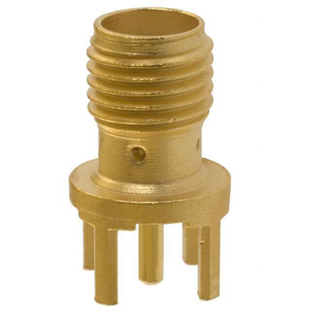
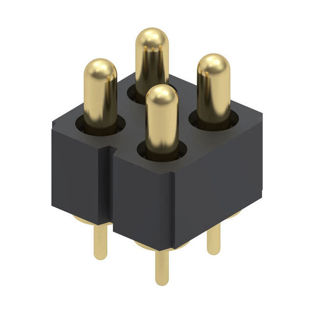
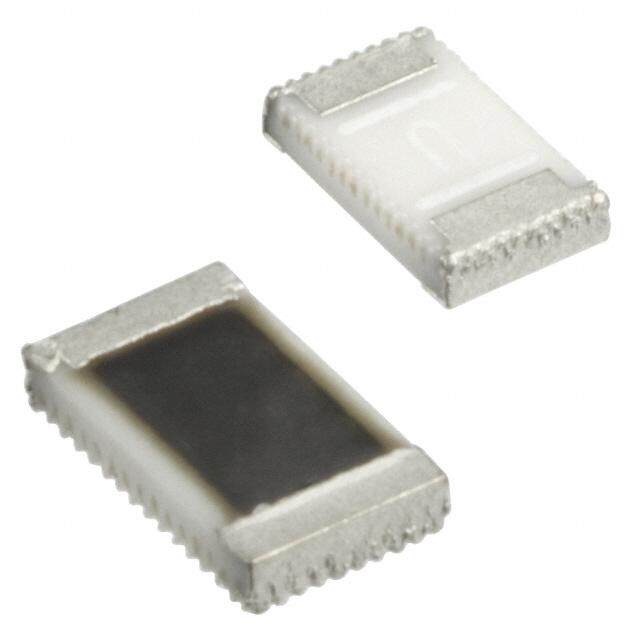
Series UB2 Low Profile Pushbuttons s e gl POLES & CIRCUITS g o T Plunger Position ( ) = Momentary Connected Terminals Throw & Switch/Lamp Schematics s er Normal Down Normal Down Notes: Switch is marked with NC, NO, COM, L+ & L–. k oc Pole Model Lamp circuit is isolated and requires an external R power source. ons UB215 ON (ON) 1 COM butt SP *UB216 ON ON 1-3 1-2 SPDT 3 NC 2 NO (+) (-) h s u P 1 COM 4 COM UB225 ON (ON) B DP 1-3 4-6 1-2 4-5 DPDT d P *UB226 ON ON 3 NC 2 NO 6 NC 5 NO (+) (-) e atD min * When in latchdown position for the alternate circuit, cap positions above the housing are: Illu .059” (1.5mm) for snap-in models & .276” (7.0mm) for PCB models. e bl a MOUNTING TYPES & SHAPES m m a gr PCB Mounting o Pr SK Square SP, Single Color LED DP, Single Color LED SP, Bicolor LED DP, Bicolor LED s k c eylo (5.2.0080) (.210.504) Typ (.52.0008) Typ (.210.504) Typ (5.2.0080) (.210.504) Typ (.52.0008) Typ (.210.504) Typ K 3 6 3 3 6 3 L (+) L (+) LC+ LC+ (5.08) 2 (10.16) (5.08) 5 2 (10.16) (5.08) 2 (10.16) (5.08) 5 2 (10.16) .200 L (–) .400 .200 L (–) .400 .200 L2- L1- .400 .200 L2- L1- .400 es 1 4 1 1 4 1 Rotari CL .(014.27) Dia Typ CL . 0(14.27) Dia Typ (2.1.0504) CL .(014.27) Dia Typ (2.1.0504) CL . 0(14.27) Dia Typ Snap-in Mounting (Solder Lug) s e Slid KK Swqituha Breuilt-in Bezel Panel Thickness: (17.4) Sq .685 .039 ~ .126” es (1.0 ~ 3.2mm) ctil a T CONTACT MATERIALS & RATINGS Tilt W Silver Contacts Power Level 5A @ 125V AC & 250V AC h G uc Gold Contacts Logic Level 0.4VA maximum @ 28V AC/DC maximum o T Complete explanation of operating range in Supplement section. s or SWITCH & LAMP TERMINALS at c di n I 01 03 For Switch & For Super Bright For Switch & For Super Bright Solder Lug Straight PC s e Bright LED & Bicolor LED Bright LED & Bicolor LED ori s es (0.2) (0.2) (0.2) (0.2) c .008 .008 .008 .008 c A (5.0) (4.0) (4.0) (4.0) (1.6) .197 .157 .157 .157 ent .063 (.20.709) .(01.309) .(01.309) .(01.309) m (0.8) Thk = (0.5) Thk = (0.5) Thk = (0.5) pple .03T2hk = (0.5) .020 .020 .020 u .020 S D96 www.nkkswitches.com
Series UB2 Low Profile Pushbuttons s e BRIGHT LED & CAPS gl g o T The electrical specifications shown are determined at a basic temperature of 25°C. LED circuit is isolated and requires an external power source. Polarity marks are on the bottom of the switch. s If the source voltage exceeds the rated voltage, a ballast resistor is required. er k c The resistor value can be calculated by using the formula in the Supplement section. o R The LED is an integral part of the switch and not available separately. s n o utt Electrical Specifications for Bright LED b h s u P 5C 5D 5F PB d e D at n Color Red Amber Green Unit mi u Ill Maximum Forward Current I 30 30 25 mA e FM bl a m Typical Forward Current I 20 20 20 mA m F a gr Forward Voltage VF 1.85 2.0 2.1 V Pro Maximum Reverse Voltage V 5 5 5 V s RM ck o Current Reduction Rate Above 25°C ∆I 0.40 0.42 0.46 mA/°C eyl F K Ambient Temperature Range –25° ~ +50° °C s e Bright Single Color LED with 1 element (+) (-) ari ot R Caps for Bright LED s e d 1 AT3074 2 AT3075 3 AT3076 Sli Sculptured Beveled Flat (6.1) (5.6) (5.6) .240 .220 .220 es ctil a T (15.0) Sq (15.0) Sq (15.0) Sq .591 .591 .591 Tilt Clear Lens Clear Lens Translucent Translucent Translucent Colored Diffuser Colored Cap Colored Diffuser h c u o T Lens/Diffuser Colors Available: Cap Colors Available: Lens/Diffuser Colors Available: s JB B JB or Clear/White White Clear/White at c di n JC C JC I Clear/Red Red Clear/Red s e JD D JD sori Clear/Amber Amber Clear/Amber es c c A JF F JF Clear/Green Green Clear/Green nt e m e Material: Polycarbonate Finish: Glossy pl p u S www.nkkswitches.com D97
Series UB2 Low Profile Pushbuttons s e gl SUPER BRIGHT LEDS & CAPS g o T The electrical specifications shown are determined at a basic temperature of 25°C. LED circuit is isolated and requires an external power source. Polarity marks are on the bottom of the switch. If the source voltage exceeds the rated voltage, ers a ballast resistor is required. The resistor value can be calculated by using the formula in the Supplement section. ck The LED is an integral part of the switch and not available separately. o R Electrical Specifications for Super Bright LEDS s n shbutto SEluepcetrro Bstraigtihc t SLeEnDssit iavree SEENLASETCITTTIEVRNEO TSDITOEAVTNIICCES Color W6hBite G6reFen 6BlGue Unit u P Maximum Forward Current I 20 30 30 mA B FM P d Typical Forward Current I 15 20 20 mA ateD F n Forward Voltage V 3.3 3.5 3.6 V mi F u Ill Maximum Reverse Voltage VRM 5 5 5 V e bl Current Reduction Rate Above 25°C ∆I 0.25 0.50 0.50 mA/°C ma F m Ambient Temperature Range –20° ~ +50° °C a gr Pro Super Bright Single Color LED with 1 element (+) (-) s Caps for Super Bright LED k c o yl e K 1JB (6.1) 2B (5.6) 3JB (5.6) .240 .220 .220 es AT3074JB AT3075B AT3076JB ari Sculptured (15.0) Sq Beveled (15.0) Sq Flat (15.0) Sq Rot Clear Lens/ .591 White Cap .591 Clear Lens/ .591 White Diffuser White Diffuser Clear Lens Clear Lens Translucent s de Translucent White Cap Translucent Sli White Diffuser White Diffuser Material: Polycarbonate Finish: Glossy es SUPER BRIGHT BICOLOR LEDS & CAPS ctil a T The electrical specifications shown are determined at a basic temperature of 25°C. LED circuit is isolated and requires an external power source. Polarity marks are on the bottom of the switch. If the source voltage exceeds the rated voltage, a ballast resistor is required. The resistor value can be calculated by using the formula in the Supplement section. Tilt The LED is an integral part of the switch and not available separately. Electrical Specifications for Super Bright Bicolor LEDs Super Bright ATTENTION 6CF 6DG h ELECTROSTATIC uc LEDs are SENSITIVE DEVICES o T Electrostatic Sensitive Color Red Green Amber Blue Unit 30 25 Maximum Forward Current I 30 30 mA ors FM * 25 for Amber * 22 for Amber at c Typical Forward Current I 20 20 15 15 mA di F n I Forward Voltage V 2.1 3.5 2.0 2.8 V F s Maximum Reverse Voltage V 4 4 4 4 V sorie Current Reduction Rate Above 25°C ∆RIM 0.40 0.33 0.33 0.33 mA/°C es F c c Ambient Temperature Range –20° ~ +50° –20° ~ +50° °C A nt Super Bright Bicolor (–) L1 * Amber color is achieved by lighting red and green e Red or Amber m LED with 2 elements (+) COM simultaneously, but is not suitable for Alternating Legends. e pl (–) L2 p Green or Blue u S D98 www.nkkswitches.com
Series UB2 Low Profile Pushbuttons Caps for Super Bright Bicolor LED es gl g o AT3074JB Sculptured AT3075B Beveled AT3076JB Flat T 1JB 2B 3JB Clear Lens/White Diffuser White Cap Clear Lens/White Diffuser s er k c .(264.10) (.52.260) (.52.260) Ro s n Clear Lens ( 1.559.01) Sq ( 1.559.01) Sq Clear Lens ( 1.559.01) Sq utto b h s Translucent Translucent Translucent u P White Diffuser White Cap White Diffuser B P d e Material: Polycarbonate Finish: Glossy D at n mi u Alternating Legend Caps for Super Bright Bicolor LED Ill e bl a AT3069J Sculptured Cap AT3070J Flat Cap with m m with Alternating Legend OOOOOOOOOOOOOOOOOOOOOOOOOOOOOOOOOOOOFFFFFFFFFFFFFFFFFFFFFFFFFNNNNNNNNFFFFFFFFFFFFFFFFFFFFFFFFFFFFFFFFFFF .(264.10) Alternating Legend OOOOOOOOOOCCCCCCCCCCCCCCCCCCCCLLLLLLLLLLLLLLLLLLLPPPPPPPPOOOOOOOOOOOOOOOOOOOEEEEEESSSSSSSSSSSSNNNNEEEEEEEEE (.52.260) Progra 4JCF Red/Green ( 1.559.01) Sq 5JCF Red/Green ( 1.559.01) Sq ocks yl Clear Lens Clear Lens Ke 4JDG 5JDG Amber/Blue Alternating Legend Filter Amber/Blue Alternating Legend Filter Material: Polycarbonate Finish: Glossy es ari Standard Alternating Legend Pairs Rot 11 12 13 14 ON OFF ON OFF START STOP OPEN CLOSE es d Sli Green/Red or Blue/Amber Green/Red or Blue/Amber Green/Red or Blue/Amber Green/Red or Blue/Amber Cap illumination is alternating Green/Red or Blue/Amber; legend text is black. es Contact factory for other Alternating Legends. ctil a T Legend illustrations are approximate representations of the actual characters on the filters. No Code No Lamp Tilt CAP TYPES & COLOR COMBINATIONS FOR NONILLUMINATED h 4 5 uc AT3073 Sculptured AT3077 Beveled o (6.1) (5.6) T .240 .220 Lens/Insert Cap Colors Available: Colors Available: s JA Clear/Black ( 1.559.01) Sq A Black ( 1.559.01) Sq ndicator I JB B Clear/White Clear Lens White es ori JC Opaque C Opaque ss Clear/Red Colored Insert Red Colored Cap ce c A JD D Clear/Amber Amber nt e Material: Polycarbonate Material: Polycarbonate m JF F e Clear/Green Finish: Glossy Green Finish: Glossy pl p u S www.nkkswitches.com D99
Series UB2 Low Profile Pushbuttons s e gl TYPICAL SWITCH DIMENSIONS g o T Bright & Super Bright LED Straight PC (6.1) .240 ockers (15.0) Sq ( 5.2.0080) Typ ( 5.2.0080) Typ 23N.C. L + (5.08) 23N.C. L + N.C.56 (5.08) R .591 .200 .200 1NCO.OM. 1NCO.OM. NCO.OM.4 (2.54) Typ (2.54) Typ L – L – s .100 .100 n o (0.5) (0.5) Typ (0.5) Typ (1.0) Typ (1.0) (1.0) Typ butt (15.24) Sq (1.5) (7.0) .0(1200.0) (4.0) .020 (4.0) .020 .039 (5.08) .039 (.50.3098) Typ h .600 .059 .276 .394 .157 .157 .200 .200 s Pu Latchdown Position B UB215SKG035C-1JC Bright Single Color LED Super Bright Single Color LED Single Pole Double Pole P d e atD Bicolor LED Straight PC (6.1) (1.0) (1.0) min .240 .039 .039 Illumable ( 1.559.01) Sq ( 5.2.0080) Typ .(013.09) 123NCNO..OCM.. LL 2 C NCNO.O.MC.. ( 5.2.0080) 123NCNO..OCM.. LL 2 C NCNO.O.MC..564 ( 5.2.0080) m L 1 L 1 a (2.54) Typ gr .100 o (0.5) (0.5) Typ (1.0) (2.54) (2.54) (1.0) Typ Pr .020 .020 .039 .100 .100 .039 (15.24) Sq (1.5) (7.0) (10.0) (4.0) (5.08) (5.08) Typ .600 .059 .276 .394 .157 .200 .200 ks Latchdown Position c o yl UB225SKG03CF-1JB Bicolor LED Side View Single Pole Double Pole e K Bright LED Solder Lug (3.0) (0.8) x (1.6) Typ .118 .032 x .063 s arie (5.08) Typ 3 L + 3 L + 6 ot (15.0) Sq .200 2N.C. (5.08) 2N.C. N.C.5 (5.08) R .591 .200 .200 1NCO.OM. 1NCO.OM. NCO.OM.4 L – L – (2.54) Typ es .100 d (1.4) (0.5) Typ (2.0) Typ (2.0) Typ Sli .055 .020 .079 .079 (19.0) Sq (1.5) (15.5) (5.0) (5.08) (5.08) Typ .748 .059 .610 .197 .200 .200 Latchdown Position s UB216KKW015F-1JF Single Color LED Side View Single Pole Double Pole e ctil Ta Super Bright LED Solder Lug (3.0) (0.8) x (1.6) Typ .118 .032 x .063 3 3 6 (5.08) Typ L + L + Tilt ( 1.559.01) Sq .200 12NCNO..OCM.. L – (5.2.0080) 12NCNO..OCM.. L – NCNO.O.MC..54 ( 5.2.0080) (2.54) Typ .100 (1.4) (4.0) (0.5) Typ (2.0) (1.0) (2.0) Typ (1.0) Typ h .055 .157 .020 .079 .039 .079 .039 uc (19.0) Sq (1.5) (15.5) (5.0) (5.08) (5.08) Typ o .748 .059 .610 .197 .200 .200 T Latchdown Position UB226KKW016F-1JF Single Color LED Side View Single Pole Double Pole s or at Bicolor LED Solder Lug (3.0) (0.8) x (1.6) Typ (1.0) (1.0) c .118 .032 x .063 .039 .039 di n I 3 3 6 (5.08) Typ L C L C s (15.0) Sq .200 (1.0) 2N.C. N.C. (5.08) 2N.C. N.C.5 (5.08) sorie .591 .039 1NCO.OM. L 2L 1 NCO.OM. .200 1NCO.OM. L 2L 1 NCO.OM.4 .200 s e c (2.54) Typ Ac .100 (1.4) (4.0) (0.5) Typ (2.0) (2.54) (2.0) Typ (2.54) .055 .157 .020 .079 .100 .079 .100 nt (19.0) Sq (1.5) (15.5) (5.0) (5.08) (5.08) me .748 .059 .610 .197 .200 .200 e Latchdown Position pl p UB216KKW01CF-1JB Bicolor LED Side View Single Pole Double Pole u S D100 www.nkkswitches.com
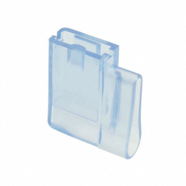
Series UB2 Low Profile Pushbuttons s e OPTIONAL ACCESSORIES gl g o T Protective Guard for Snap-in Model AT4141 s er Opens 90° k c o Closes manually R s (11.1) on Materials: .437 (.1795.21) hbutt s (21.7) (8.05) u Cover: Clear Polycarbonate .854 .317 P B Base: Black GFR Polyamide P Cap Height ed (19.5) When (16.1) D at .768 Assembled .634 n (21.5) (6.5) (19.1) mi Recommended Panel Thickness: .846 .256 .752 u Ill .039” ~ .106” (1.0mm ~ 2.7mm) e bl a m m a gr Spring Loaded Protective Guard for Snap-in Mounting of PCB Model Pro AT4170 ks c o Opens 180° yl e K Closes automatically (11.1) es .437 (.1781.31) ari ot (21.7) (15.64) R .854 .616 Materials: Cover: Clear Polycarbonate es (19.5) (15.64) d Base: Black Polyamide .768 (21.5) (6.5) (13.5) .616 (18.0) Sli .846 .256 .531 .709 Coil Spring: Stainless Steel s e Recommended Panel Thickness: Recommended Panel-to-PCB Range: 180° actil T .039” ~ .126” .531” (13.5mm) (1.0mm ~ 3.2mm) Tilt (13.5) .531 (18.8) Sq .740 h c u o T (40.0) Min* 1.575 Protective AT4170 Guard ors at 2 dic Panel In (21.7) .854 s Installation e ori 1 Install switch onto 3 Switch ss e (21.5) PC board. Acc .846 2 Snap protective 1 (21.5) .846 (N) guard into panel. PC Board nt (N) = Number of switches 3 Join the two me * Minimum dimension allows opening of cover to 180° assemblies. ple p u S www.nkkswitches.com D101
Series UB2 Low Profile Pushbuttons s e gl OPTIONAL ACCESSORIES g o T Spring Loaded Protective Guard for Snap-in Model s er k c o R AT4142 Opens 180° s Closes automatically n o utt b h s u P Materials: B P ed Cover: Clear Polycarbonate (11.1) atD Base: Black GFR Polyamide .437 (19.1) n .752 mi Coil Spring: Stainless Steel Illu (.2815.47) ( 8.3.0175) e bl a m Cap Height gram Recommended Panel Thickness: (.1796.85) (21.5) WAshseenm bled (6.5) (.1663.41) (19.1) Pro .039” ~ .106” (1.0mm ~ 2.7mm) .846 .256 .752 s k c o yl e K Dust Cover AT4145 Not for use with barriers. s e ari ot (17.1) R .673 Materials: Lid: Clear PVC s Operating temperature range: e d (17.1) Sli Gaske0t°: C P ~o ly+e7t0hy°Cle n(3e2°F ~ 158°C). (.1676.09) Sq .673(17.7) .697 s Tactile Recommended Panel Thickness CWAashspee nHmebiglehdt (6.4) (.20.958) (.1679.77) (25.2) Sq .039” ~ .098” (1.0mm ~ 2.5mm) .252 .992 Tilt Barriers for Snap-in Mount h AT4143 AT4144 c Tou End Center (2.945.268) (20.07) (4.1) Typ .790 .161 A s (4.8) or .189 at Indic (.2812.07) (.1532.34) .(1678.45) Min s e ori End Position Center Position s ces . 0(14.27) . 0(14.27) c (20.07) Cutouts for more than 1 Switch: A .790 nt A = .799” (20.3mm) x Number of Switches + me Material: Polyamide .063” (1.6mm) e pl p u S D102 www.nkkswitches.com
Series UB2 Low Profile Pushbuttons s e LEGENDS gl g o T NKK Switches can provide custom legends for caps. Contact factory for more information. s er k c o R Suggested Printable Area for UB2 Lens, Film Insert or Diffuser s n Recommended Methods: Laser Etch on clear lens, Screen Print or Pad Print on lens; utto b Laser Print on film insert. sh u P B P Shaded areas are printable areas. d e D at n mi u Beveled Cap Flat Cap Sculptured Cap Ill e bl a m m a Lens gr ON Lens Lens Pro Lens s (12.96) Dia (0.76) Typ ck ( 1.533.51) Sq ( 0.0.7360) Typ ( 1.45.1408) Dia . 0 3 0 eylo (15.0) Sq .570 K .591 Film Insert O F s F Diffuser arie (0.5) R ot (0.5) R .020 R .020 Film Insert Film Insert (9.98) Sq (0.76) Typ or Diffuser or Diffuser s .393 .030 de (.1415.53) Sq (11.88) Dia (0.76) Typ Sli (11.88) Sq (0.76) Typ .468 .030 .468 .030 (13.4) Sq (13.4) Sq .528 .528 s e ctil Film Insert: Clear Polyester 4 mil maximum thickness Ta Tilt h c u o T s or at c di n I s e ori s s e c c A nt e m e pl p u S www.nkkswitches.com D103