ICGOO在线商城 > 继电器 > 信号继电器,高达 2 A > TX2-5V
 Datasheet下载
- 型号: TX2-5V
- 制造商: Panasonic Corporation
- 库位|库存: xxxx|xxxx
- 要求:
| 数量阶梯 | 香港交货 | 国内含税 |
| +xxxx | $xxxx | ¥xxxx |
查看当月历史价格
查看今年历史价格
TX2-5V产品简介:
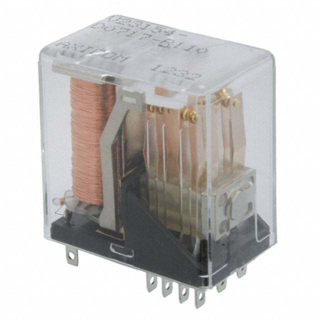
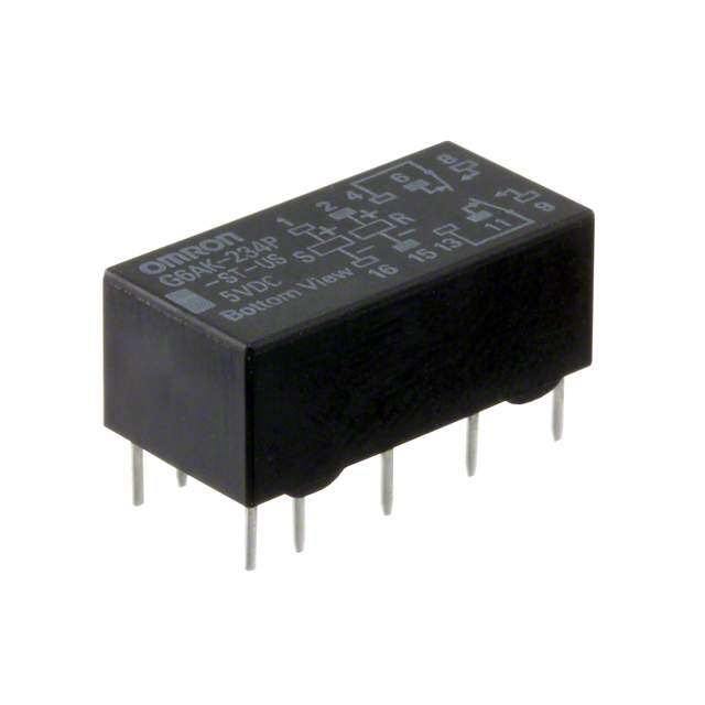
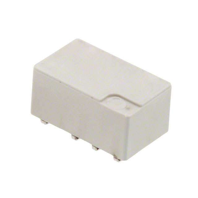
ICGOO电子元器件商城为您提供TX2-5V由Panasonic Corporation设计生产,在icgoo商城现货销售,并且可以通过原厂、代理商等渠道进行代购。 TX2-5V价格参考¥17.75-¥30.38。Panasonic CorporationTX2-5V封装/规格:信号继电器,高达 2 A, Telecom Relay DPDT (2 Form C) Through Hole。您可以下载TX2-5V参考资料、Datasheet数据手册功能说明书,资料中有TX2-5V 详细功能的应用电路图电压和使用方法及教程。
Panasonic Electric Works的TX2-5V是一款额定电流高达2A的信号继电器,广泛应用于需要小信号控制大负载的电子和电气系统中。该继电器线圈工作电压为5V DC,适合低电压控制电路,具有灵敏度高、响应快、可靠性强等特点。

TX2-5V常用于通信设备、办公自动化设备(如打印机、复印机)、家用电器(如空调、洗衣机中的控制板)、工业自动化控制系统以及测量仪器中。其紧凑的结构设计使其适用于PCB板安装,节省空间,适合高密度电路布局。

在智能家居系统中,TX2-5V可用于灯光控制、温控开关等场景;在安防设备中,可用于报警器或门禁系统的信号切换。此外,在电源管理模块中,它也常作为负载通断控制元件,实现对小型电机、电磁阀或指示灯的精准控制。

由于其具备良好的绝缘性能和耐久性(机械寿命高达1000万次,电气寿命达10万次),TX2-5V在长期运行环境中表现稳定,是中小功率信号控制应用的理想选择。
| 参数 | 数值 |
| 产品目录 | |
| 描述 | RELAY TELECOM DPDT 2A 5V低信号继电器 - PCB 2A 5VDC DPDT NON-LATCHING PCB |
| 产品分类 | |
| 品牌 | Panasonic Electric Works |
| 产品手册 | |
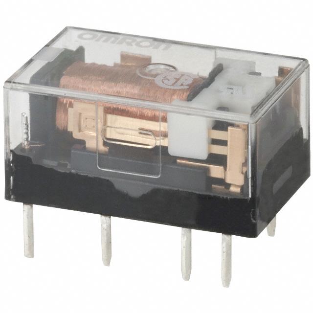
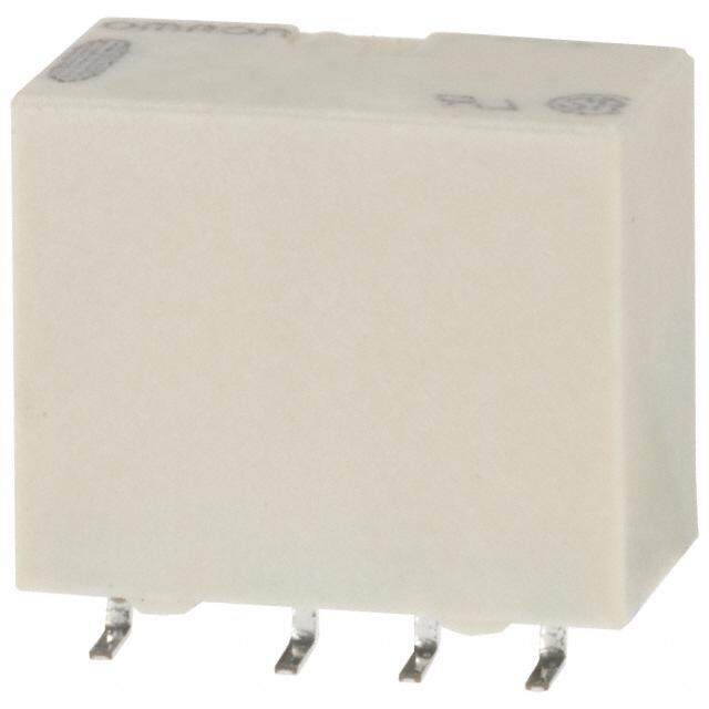
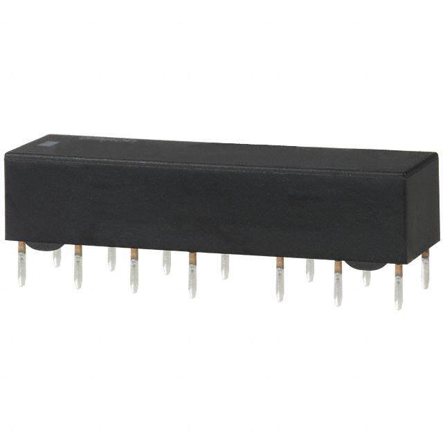
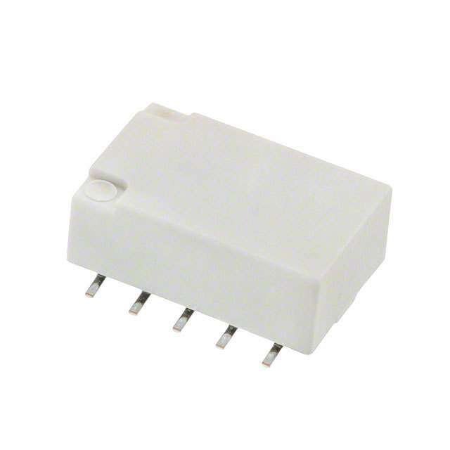
| 产品图片 |
|
| rohs | RoHS 合规性豁免无铅 / 符合限制有害物质指令(RoHS)规范要求 |
| 产品系列 | 低信号继电器 - PCB,Panasonic Industrial Devices TX2-5VTX |
| mouser_ship_limit | 该产品可能需要其他文件才能进口到中国。 |
| 数据手册 | |
| 产品型号 | TX2-5V |
| 产品 | Low Profile Relays |
| 产品培训模块 | http://www.digikey.cn/PTM/IndividualPTM.page?site=cn&lang=zhs&ptm=17685 |
| 产品目录绘图 |
|
| 产品目录页面 | |
| 产品种类 | 低信号继电器 - PCB |
| 介入损耗 | 0.8 dB at 1 GHz |
| 关闭电压(最小值) | 0.5 VDC |
| 其它名称 | 255-1031 |
| 其它有关文件 | 点击此处下载产品Datasheet点击此处下载产品Datasheet点击此处下载产品Datasheet点击此处下载产品Datasheet |
| 功耗 | 140 mW |
| 包装 | 管件 |
| 商标 | Panasonic Industrial Devices |
| 安装类型 | 通孔 |
| 安装风格 | Through Hole |
| 导通电压(最大值) | 3.75 VDC |
| 封装 | Tube |
| 工作时间 | 4ms |
| 工作温度 | -40°C ~ 85°C |
| 工厂包装数量 | 40 |
| 开关电压 | 220VDC - 最小值 |
| 最大开关电流 | 2 A |
| 标准包装 | 40 |
| 特性 | 密封式 - 全部 |
| 端子类型 | PC 引脚 |
| 端接类型 | Solder Pin |
| 线圈功率 | 140 mW |
| 线圈电压 | 5VDC |
| 线圈电流 | 28.1mA |
| 线圈电阻 | 178 欧姆 |
| 线圈类型 | 无锁存 |
| 绝缘 | 20 dB at 1 GHz |
| 继电器类型 | 电信 |
| 触头外形 | DPDT(2 C 型) |
| 触头材料 | Silver(Ag),Gold(Au) |
| 触点形式 | DPDT (2 Form C) |
| 触点电流额定值 | 2 A |
| 触点额定值 | 2 A at 30 VDC |
| 释放时间 | 4ms |
| 额定接触(电流) | 2A |


- 商务部:美国ITC正式对集成电路等产品启动337调查
- 曝三星4nm工艺存在良率问题 高通将骁龙8 Gen1或转产台积电
- 太阳诱电将投资9.5亿元在常州建新厂生产MLCC 预计2023年完工
- 英特尔发布欧洲新工厂建设计划 深化IDM 2.0 战略
- 台积电先进制程称霸业界 有大客户加持明年业绩稳了
- 达到5530亿美元!SIA预计今年全球半导体销售额将创下新高
- 英特尔拟将自动驾驶子公司Mobileye上市 估值或超500亿美元
- 三星加码芯片和SET,合并消费电子和移动部门,撤换高东真等 CEO
- 三星电子宣布重大人事变动 还合并消费电子和移动部门
- 海关总署:前11个月进口集成电路产品价值2.52万亿元 增长14.8%
PDF Datasheet 数据手册内容提取
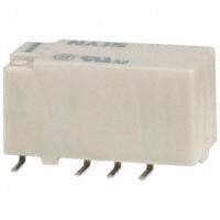
2, 000 V AC TX RELAYS breakdown voltage, 2 Form C and 2 A relays FEATURES TYPICAL APPLICATIONS 1.2,000 V breakdown voltage between 1.Communications (xDSL, contact and coil Transmission) 2.Outstanding surge resistance. 2.Measurement 1,500 V 10×160μ sec. (FCC part 68) 3.Security (open contacts) 4.Home appliances, and audio/visual 2,500 V 2×10μ sec. (Telcordia) equipment (contact and coil) 5.Medical equipment 3.Nominal operating power: High sensitivity of 140mW RoHS compliant 4.High contact capacity: 2 A 30 V DC 5.Compact size 15.0 (L) × 7.4 (W) × 8.2 (H) mm .591 (L) × .291 (W) × .323 (H) inch 6.High contact reliability High contact reliability is achieved by the use of gold-clad twin crossbar contacts, low-gas formation materials, mold sealing the coil section, and by controlling organic gas in the coil. *We also offer a range of products with AgPd contacts suitable for use in low level load analog circuits (Max. 10V DC 10 mA). ORDERING INFORMATION TX 2 Contact arrangement 2: 2 Form C Surface-mount availability Nil: Standard PC board terminal type SA:SA type Operating function Nil: Single side stable LT: 2 coil latching Terminal shape Nil:Standard PC board terminal or surface-mount terminal Nominal coil voltage (DC)* 3, 4.5, 5, 6, 9, 12, 24V Contact material Nil:Standard contact (Ag+Au clad) 1: AgPd contact (low level load); AgPd+Au clad (stationary), AgPd (movable) Packing style Nil:Tube packing X: Tape and reel (picked from 1/3/4/5-pin side) Z: Tape and reel packing (picked from the 8/9/10/12-pin side) Note: In case of 5 V transistor drive circuit, it is recommended to use 4.5 V type relay. –1– ASCTB18E 201407-T
TX TYPES 1. Standard PC board terminal Contact Nominal coil Single side stable 2 coil latching arrangement voltage Part No. Part No. 3 V DC TX2-3V TX2-LT-3V 4.5 V DC TX2-4.5V TX2-LT-4.5V 5 V DC TX2-5V TX2-LT-5V 2 Form C 6 V DC TX2-6V TX2-LT-6V 9 V DC TX2-9V TX2-LT-9V 12 V DC TX2-12V TX2-LT-12V 24 V DC TX2-24V TX2-LT-24V Standard packing: Tube: 40 pcs.; Case: 1,000 pcs. Note: Please add “-1” to the end of the part number for AgPd contacts (low level load). 2. Surface-mount terminal 1) Tube packing Contact Nominal coil Single side stable 2 coil latching arrangement voltage Part No. Part No. 3 V DC TX2SA-3V TX2SA-LT-3V 4.5 V DC TX2SA-4.5V TX2SA-LT-4.5V 5 V DC TX2SA-5V TX2SA-LT-5V 2 Form C 6 V DC TX2SA-6V TX2SA-LT-6V 9 V DC TX2SA-9V TX2SA-LT-9V 12 V DC TX2SA-12V TX2SA-LT-12V 24 V DC TX2SA-24V TX2SA-LT-24V Standard packing: Tube: 40 pcs.; Case: 1,000 pcs. Note: Please add “-1” to the end of the part number for AgPd contacts (low level load). 2) Tape and reel packing Contact Nominal coil Single side stable 2 coil latching arrangement voltage Part No. Part No. 3 V DC TX2SA-3V-Z TX2SA-LT-3V-Z 4.5 V DC TX2SA-4.5V-Z TX2SA-LT-4.5V-Z 5 V DC TX2SA-5V-Z TX2SA-LT-5V-Z 2 Form C 6 V DC TX2SA-6V-Z TX2SA-LT-6V-Z 9 V DC TX2SA-9V-Z TX2SA-LT-9V-Z 12 V DC TX2SA-12V-Z TX2SA-LT-12V-Z 24 V DC TX2SA-24V-Z TX2SA-LT-24V-Z Standard packing: Tape and reel: 500 pcs.; Case: 1,000 pcs. Notes:1.Tape and reel packing symbol “-Z” is not marked on the relay. “X” type tape and reel packing (picked from 1/2/3/4-pin side) is also available. 2.Please add “-1” to the end of the part number for AgPd contacts (low level load). RATING 1. Coil data 1) Single side stable Nominal operating Nominal coil Pick-up voltage Drop-out voltage Coil resistance Nominal operating Max. applied voltage voltage (at 20°C 68°F) (at 20°C 68°F) [±10%] c(autr r2e0n°tC 68°F) [±10%] (at 20°C 68°F) power (at 20°C 68°F) 3 V DC 46.7 mA 64.3 Ω 4.5 V DC 31 mA 145 Ω 5 V DC 75%V or less of 10%V or more of 28.1 mA 178 Ω 6 V DC nominal voltage* nominal voltage* 23.3 mA 257 Ω 140 mW 150%V of nominal voltage 9 V DC (Initial) (Initial) 15.5 mA 579 Ω 12 V DC 11.7 mA 1,028 Ω 24 V DC 5.8 mA 4,114 Ω 2) 2 coil latching Nominal operating Coil resistance Nominal operating Novmoilntaagl ecoil (aSt e2t0 v°Col t6a8g°eF ) (Raet s2e0t° Cvo 6lt8a°gFe) [±10%] c(autr r2e0n°tC 68°F) [±10%] (at 20°C 68°F) power Max(a. at p2p0l°iCed 6 v8o°lFtage Set coil Reset coil Set coil Reset coil Set coil Reset coil 3 V DC 66.7 mA 66.7 mA 45 Ω 45 Ω 4.5 V DC 44.5 mA 44.5 mA 101.2 Ω 101.2 Ω 5 V DC 75%V or less of 75%V or less of 40 mA 40 mA 125 Ω 125 Ω 6 V DC nominal voltage* nominal voltage* 33.3 mA 33.3 mA 180 Ω 180 Ω 200 mW 200 mW 150%V of nominal voltage 9 V DC (Initial) (Initial) 22.2 mA 22.2 mA 405 Ω 405 Ω 12 V DC 16.7 mA 16.7 mA 720 Ω 720 Ω 24 V DC 8.3 mA 8.3 mA 2,880 Ω 2,880 Ω *Pulse drive (JIS C 5442-1986) –2– ASCTB18E 201407-T
TX 2. Specifications Characteristics Item Specifications Arrangement 2 Form C Initial contact resistance, max. Max. 100 mΩ (By voltage drop 6 V DC 1A) Contact Standard contact: Ag+Au clad, Contact material AgPd contact (low level load): AgPd+Au clad (stationary), AgPd (movable) Nominal switching capacity Standard contact: 2 A 30 V DC, AgPd contact: 1 A 30 V DC (resistive load) Max. switching power Standard contact: 60 W (DC), AgPd contact: 30 W (DC) (resistive load) Max. switching voltage 220V DC Rating Max. switching current Standard contact: 2 A, AgPd contact: 1 A Min. switching capacity (Reference value)*1 10μA 10mV DC Nominal operating Single side stable 140 mW (3 to 24 V DC) power 2 coil latching 200 mW (3 to 24 V DC) Insulation resistance (Initial) Min. 1,000MΩ (at 500V DC) Measurement at same location as “Initial breakdown voltage” section. Between open contacts 1,000 Vrms for 1min. (Detection current: 10mA) Breakdown voltage Between contact and coil 2,000 Vrms for 1min. (Detection current: 10mA) (Initial) Between contact sets 1,000 Vrms for 1min. (Detection current: 10mA) Electrical Surge breakdown Between open contacts 1,500 V (10×160μs) (FCC Part 68) characteristics voltage (Initial) Between contacts and coil 2,500 V (2×10μs) (Telcordia) Temperature rise (at 20°C 68°F) Max. 50°C (By resistive method, nominal coil voltage applied to the coil; contact carrying current: 2A.) Operate time [Set time] (at 20°C 68°F) Max. 4 ms [Max. 4 ms] (Nominal coil voltage applied to the coil, excluding contact bounce time.) Release time [Reset time] (at 20°C 68°F) Max. 4 ms [Max. 4 ms] (Nominal coil voltage applied to the coil, excluding contact bounce time.) (without diode) Functional Min. 750 m/s2 (Half-wave pulse of sine wave: 6 ms; detection time: 10μs.) Shock resistance Mechanical Destructive Min. 1,000 m/s2 (Half-wave pulse of sine wave: 6 ms.) characteristics Functional 10 to 55 Hz at double amplitude of 3.3 mm (Detection time: 10μs.) Vibration resistance Destructive 10 to 55 Hz at double amplitude of 5 mm Mechanical Min. 108 (at 180 cpm) Expected life Electrical (Standard contact) Min. 105 (2 A 30 V DC resistive), 5×10⁵ (1 A 30 V DC resistive) (at 20 cpm) Ambient temperature: –40°C to +85°C (up to 24 V coil) –40°F to +185°F (up to 24 V coil) Conditions for operation, transport and storage*2 [–40°C to +70°C (48 V coil) –40°F to +158°F (48 V coil)]; Conditions Humidity: 5 to 85% R.H. (Not freezing and condensing at low temperature) Max. operating speed (at rated load) 20 cpm Unit weight Approx. 2 g .071 oz Notes:*1 This value can change due to the switching frequency, environmental conditions, and desired reliability level, therefore it is recommended to check this with the actual load. (AgPd contact type is available for low level load switching [10V DC, 10mA max. level]) *2 Refer to “AMBIENT ENVIRONMENT” in GENERAL APPLICATION GUIDELINES. REFERENCE DATA 1. Maximum switching capacity 2. Life curve 3. Mechanical life Tested sample: TX2-5V, 10 pcs. Operating speed: 180 cpm V100 % 3.0 e, 90 g Switching current, A 0012....4500 DC resistive load ×4of operations 10105320000 3re0sVis DtivCe load gainst the rated volta 4567800000 Pick-up voltage MMainx.. 00..23 No. 10 Ratio a 2300 Drop-out voltage Max. 10 Min. 0 0 0 20 30 50 100 200300 1.0 2.0 10 100 1,000 10,000 Contact voltage, V Switching current, A No. of operations, ×104 4. Electrical life (2A 30V DC resistive load) 5. Coil temperature rise Tested sample: TX2-5V, 6 pcs. Tested sample: TX2-5V, 6 pcs. Operating speed: 20 cpm Point measured: Inside the coil Change of pick-up and drop-out voltage Change of contact resistance Ambient temperature: 25°C 77°F, 85°C 185°F Ratio against the rated voltage, %V1234567890000000000 DPriocpk--uopu tv vooltlataggee MMMaainxx... ΩContact resistance, m1234567890000000000 MMainx.. °Temperature rise, C367245000000 ++220028AAAA55°°CC++7178°5F°F 10 Min. 10 10 0 0 0 1 2 3 4 5 6 7 8 9 10 1 2 3 4 5 6 7 8 9 10 100 110 120 130 140 150 No. of operations, ×104 No. of operations, ×104 Coil applied voltage, % –3– ASCTB18E 201407-T
TX 6-(1). Operate and release time (with diode) 6-(2). Operate and release time (without diode) 7. Ambient temperature characteristics Tested sample: TX2-5V, 10 pcs. Tested sample: TX2-5V, 10 pcs. Tested sample: TX2-5V, 5 pcs. 5 5 Operate time Operate time % me, ms 4 Max. Release time me, ms4 Max. Release time hange, 40 Dvoroltapg-oeut x Operate and release ti 23 MMMaiinnx... Operate and release ti23 MMMaiinxn... –40 –20 0 Rate of c2–202A00m4b0ient6 t0Pemickp8-e0xurpa tvuorelta, g°Ce 1 1 –40 0 0 70 80 90 100 110 120 70 80 90 100 110 120 Coil applied voltage, %V Coil applied voltage, %V 8-(1). High frequency characteristics 8-(2). High frequency characteristics 9. Malfunctional shock (single side stable) (Isolation) (Insertion loss) Tested sample: TX2-5V, 6 pcs. Tested sample: TX2-12V, 2 pcs. Tested sample: TX2-12V, 2 pcs. Z' Z XX' Y DEneeerngeizrgeidz ecdo ncdointidointion Y 1000m/s2 Y' B d Isolation, dB100 nsertion loss, 10..08 1000mX/s2 10Z00m/s2 50 I 0.6 1000m/s2 1000m/s2 Z' X' 0.4 0.2 1000m/s2 Y' 10 100 1,000 10 100 1,000 Frequency, MHz Frequency, MHz 10-(1). Influence of adjacent mounting 10-(2). Influence of adjacent mounting Tested sample: TX2-12V, 6 pcs. Tested sample: TX2-12V, 6 pcs. Rate of change, %–505 Pick-up voltage ONONON Rate of change, %–505 Pick-up voltage OONNON Rate of change, %–505 Drop-out voltage OFOFFFOFF Rate of change, %–505 Drop-out voltage OOFFFFOFF 0 2 4 6 8 10 0 2 4 6 8 10 .079.157.236.315.394 .079.157.236.315.394 Inter-relay distance , mminch Inter-relay distance , mminch 11. Pulse dialing test Tested sample: TX2-5V, 6 pcs. (35 mA 48 V DC wire spring relay load) Change of pick-up and drop-out voltage Change of contact resistance 100 100 V % 90 90 Cir4c+–8uVi tDC0μ.0F8445588 ΩΩ0μ.0F8 43TX o against the rated voltage, 345678000000 DPriocpk--ouupt vvoollttaaggee MMMaainxx... ΩContact resistance, m 345678000000 MMainx.. Wire spring relay Rati 20 Min. 20 10 10 0 0 10 20 30 40 50 10 20 30 40 50 No. of operation, ×104 No. of operations, ×104 Note: Data of surface-mount type are the same as those of PC board terminal type. –4– ASCTB18E 201407-T
TX DIMENSIONS (mm inch) The CAD data of the products with a CAD Data mark can be downloaded from: http://industrial.panasonic.com/ac/e/ 1. Standard PC board terminal and Self clinching terminal CAD Data Single side stable type 2 coil latching type External dimensions External dimensions Standard PC board terminal Standard PC board terminal 15.00 7.40 15.00 7.40 .591 .291 .591 .291 .00.26658.3.2203 .00.2665 8.3.2203 1.0.00..12545005 5.2.0080 2.1.5040 3.1.5308 5.2.0080 0.0.2150 1.0.00..12545005 5.2.0080 2.1.5040 3.1.5308 5.2.0080 0.0.2150 General tolerance: ±0.3 ±.012 General tolerance: ±0.3 ±.012 PC board pattern Schematic (Bottom view) PC board pattern Schematic (Bottom view) (Bottom view) Single side stable (Bottom view) 2 coil latching 2.54 1.04.0106 +1 3 4 5 2.54 1.520.70 +1 3 4 5 6+ .100 .100 5.08 5.08 .200 – .200 – – 12 10 9 8 12 10 9 8 7 88--1.0.03 9d idai.a. Direction indication 1100--1.0.03 9d idai.a. Direction indication Tolerance: ±0.1 ±.004 (Deenergized condition) Tolerance: ±0.1 ±.004 (Reset condition) 2. Surface-mount terminal CAD Data External dimensions (General tolerance: ±0.3 ±.012) Suggested mounting pad (Top view) (Tolerance: ±0.1 ±.004) Type Single side stable type 2 coil latching type Single side stable type 2 coil latching type SA type .51951 8.3.223 .383.14 .279.41 0.25 .51951 8.3.223 .383.14 .279.41 0.25 .31.2146.0319 5.2.0080 .21.0504 .31.2146.0319 .52.0008 .21.0504 0.5 0.0.6256 5.2.0080 .010 0.5 0.0.6256 5.2.0080 .010 7.2.2845 7.2.2845 .020 5.08 2.54 9.4±0.5 .020 5.08 2.54 9.4±0.5 .200 .100 .370±.020 .200 .100 .370±.020 Schematic (Top view) Single side stable 2 coil latching –12 10 9 8 –12 10 9 8 7– + + + 1 3 4 5 1 3 4 5 6 Direction indication Direction indication (Deenergized condition) (Reset condition) –5– ASCTB18E 201407-T
TX NOTES 1. Packing style 2. Automatic insertion 1) The relay is packed in a tube with the To maintain the internal function of the relay orientation mark on the left side, as relay, the chucking pressure should not shown in the figure below. exceed the values below. Chucking pressure in the direction A: Orientation (indicates PIN No.1) stripe 4.9 N {500gf} or less Chucking pressure in the direction B: 9.8 N {1 kgf} or less Chucking pressure in the direction C: Stopper (gray) Stopper (green) 9.8 N {1 kgf} or less 2) Tape and reel packing (surface-mount C B terminal type) A (1) Tape dimensions mm inch R(Ze tlaypy ep)olarity bar.015.95+ + 00.00.014ddiaia...027.09 .41.507 1.0.7659 .001.46 C Please chuck the portion. A B 11.5 .453 15.5 Avoid chucking the center of the relay. .610 In addition, excessive chucking pressure Relays 1.663.00 10.0.D394 2.944.05±±0.0.312 9.2±0.2 to the pinpoint of the relay should be .362±.008 Tape coming out direction avoided. (2) Dimensions of plastic reel mm inch For general cautions for use, please refer to the “Cautions for use of Signal Relays” or “General 2.0 Application Guidelines”. .079 380 dia. 13 dia. 21 dia. 14.961 dia. .512 dia. .827 dia. 80 dia. 3.150 dia. –6– ASCTB18E 201407-T
Mouser Electronics Authorized Distributor Click to View Pricing, Inventory, Delivery & Lifecycle Information: P anasonic: TX2-4.5V TX2-L2-5V TX2-5V TX2SA-5V TX2SA-5V-Z TX2-12V TX2SA-12V TX2-24V TX2SA-24V TX2SA-24V- Z TX2SA-12V-1 TXS2SL-9V-1 TX2SL-3V TX2-L-3V TX2-3V TX2SA-L2-3V TX2SA-3V TX2SA-L2-4.5V TX2SA- 4.5V TX2SS-4.5V TX2-L-5V TX2-9V TX2SA-L2-5V TX2SL-5V TX2SA-L2-12V TX2SA-12V-Z TX2SL-24V TX2SS- 24V TX2-48V TX2SS-48V TX2-L2-4.5V TX2-L2-9V TX2-L-4.5V TX2SL-4.5V TX2SA-9V TX2-L2-24V TX2-L2-12V TX2SS-5V TX2SL-12V TX2-LT-12V TX2-LT-24V TX2-LT-4.5V TX2SA-LT-12V TX2SA-LT-3V TX2SA-LT-4.5V TX2SA-LT-4.5V-Z TX2SA-LT-5V TX2SA-LT-5V-Z TX2SL-LT-3V TX2SL-LT-3V-X TX2SL-LT-4.5V TX2SA-LT-12V-Z TX2SA-3V-1 TX2SA-LT-24V-Z TX2SS-LT-5V-Z TX2SA-LT-12V-X TX2-L-12V-1 TX2SS-LT-12V-X TX2SS-LT-5V-X TX2SA-12V-1-X TX2SA-12V-1-Z TX2-L-9V-1 TX2SA-3V-1-Z TX2SS-LT-12V-Z TX2SS-LT-3V TX2SA-3V-1-X TX2SS-LT-5V