ICGOO在线商城 > 继电器 > 信号继电器,高达 2 A > TQ2-L2-9V

 Datasheet下载
- 型号: TQ2-L2-9V
- 制造商: Panasonic Corporation
- 库位|库存: xxxx|xxxx
- 要求:
| 数量阶梯 | 香港交货 | 国内含税 |
| +xxxx | $xxxx | ¥xxxx |
查看当月历史价格
查看今年历史价格
TQ2-L2-9V产品简介:
ICGOO电子元器件商城为您提供TQ2-L2-9V由Panasonic Corporation设计生产,在icgoo商城现货销售,并且可以通过原厂、代理商等渠道进行代购。 TQ2-L2-9V价格参考¥询价-¥询价。Panasonic CorporationTQ2-L2-9V封装/规格:信号继电器,高达 2 A, Telecom Relay DPDT (2 Form C) Through Hole。您可以下载TQ2-L2-9V参考资料、Datasheet数据手册功能说明书,资料中有TQ2-L2-9V 详细功能的应用电路图电压和使用方法及教程。
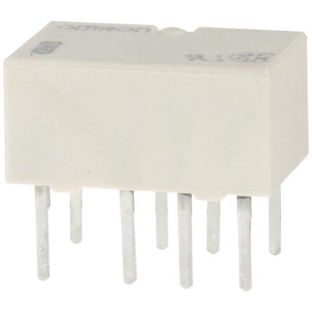
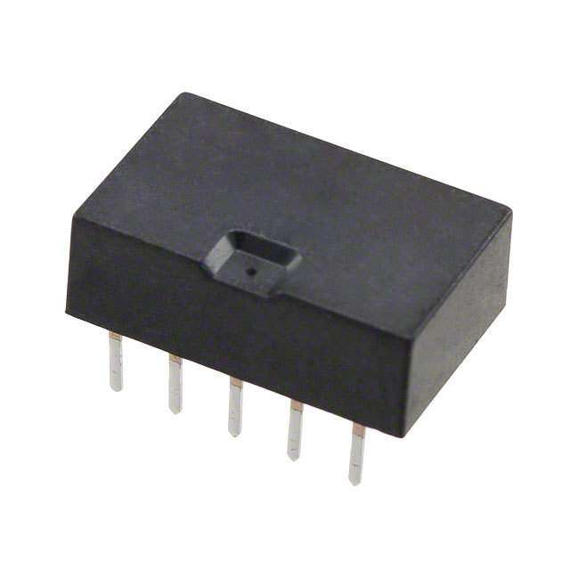
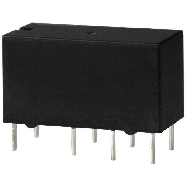
TQ2-L2-9V 是 Panasonic Electric Works 生产的一款信号继电器,额定电流高达 2 A,适用于多种电子和电气控制系统。该继电器线圈电压为 9V DC,具有灵敏动作、低功耗和高可靠性等特点,广泛应用于工业自动化、通信设备、办公自动化设备及家用电器等领域。

典型应用场景包括:作为控制信号的切换元件,在PLC(可编程逻辑控制器)、测量仪器、安防系统中实现小电流信号对较大负载的控制;在电源管理电路中用于通断直流电机、电磁阀、指示灯等负载;也可用于通信设备中的信号隔离与转换,提升系统的稳定性和抗干扰能力。

TQ2-L2-9V 采用标准封装设计,便于PCB安装,具备良好的耐环境性能,适合在温度变化较大的工业环境中长期稳定运行。其机械寿命和电气寿命均较长,满足高可靠性应用需求。此外,该继电器符合多项国际安全认证标准,适用于对安全性要求较高的场合。

综上所述,TQ2-L2-9V 凭借其紧凑结构、稳定性能和广泛兼容性,是自动化控制、电子设备和工业系统中理想的信号切换解决方案。
| 参数 | 数值 |
| 产品目录 | |
| 描述 | RELAY TELECOM DPDT 1A 9V低信号继电器 - PCB 1A 9VDC DPDT 2 COIL LATCHING PCB |
| 产品分类 | |
| 品牌 | Panasonic Electric Works |
| 产品手册 | |
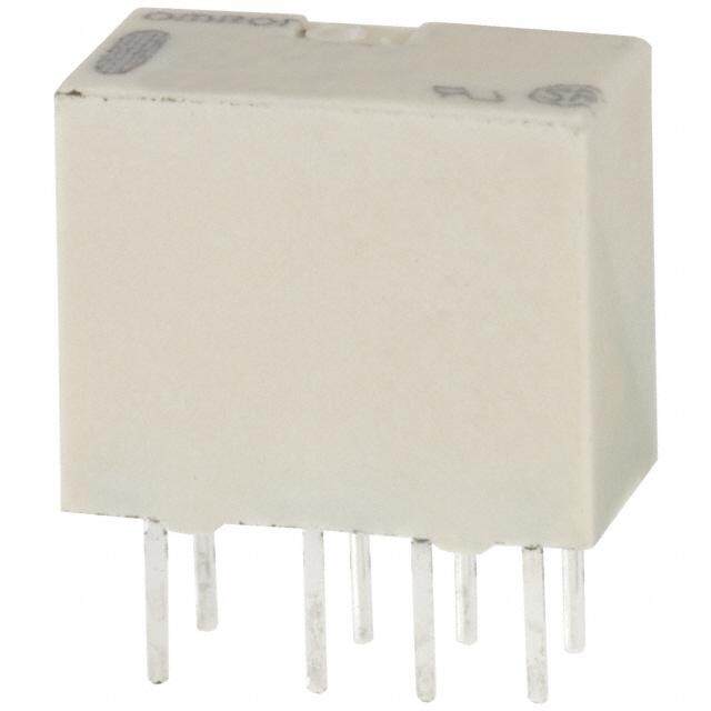
| 产品图片 |
|
| rohs | RoHS 合规性豁免无铅 / 符合限制有害物质指令(RoHS)规范要求 |
| 产品系列 | 低信号继电器 - PCB,Panasonic Industrial Devices TQ2-L2-9VTQ |
| mouser_ship_limit | 该产品可能需要其他文件才能进口到中国。 |
| 数据手册 | |
| 产品型号 | TQ2-L2-9V |
| 产品 | Low Profile Relays |
| 产品目录绘图 |
|
| 产品目录页面 | |
| 产品种类 | 低信号继电器 - PCB |
| 介入损耗 | 0.6 dB at 1 GHz |
| 关闭电压(最小值) | - |
| 其它名称 | 255-1355 |
| 其它有关文件 | |
| 功耗 | 200 mW |
| 包装 | 管件 |
| 商标 | Panasonic Industrial Devices |
| 安装类型 | 通孔 |
| 安装风格 | Through Hole |
| 导通电压(最大值) | 6.75 VDC |
| 封装 | Tube |
| 工作时间 | 3ms |
| 工作温度 | -40°C ~ 70°C |
| 工厂包装数量 | 50 |
| 开关电压 | 125VAC,110VDC - 最小值 |
| 最大开关电流 | 1 A |
| 标准包装 | 50 |
| 特性 | - |
| 端子类型 | PC 引脚 |
| 端接类型 | Solder Pin |
| 线圈功率 | 200 mW |
| 线圈电压 | 9VDC |
| 线圈电流 | 22.2mA |
| 线圈电阻 | 405 欧姆 |
| 线圈类型 | 锁存,双线圈 |
| 绝缘 | 15 dB at 1 GHz |
| 继电器类型 | 电信 |
| 触头外形 | DPDT(2 C 型) |
| 触头材料 | Silver(Ag),Gold(Au) |
| 触点形式 | DPDT (2 Form C) |
| 触点电流额定值 | 1 A |
| 触点额定值 | 1 A at 30 VDC / 500 mA at 125 VAC |
| 释放时间 | 3ms |
| 额定接触(电流) | 1A |


- 商务部:美国ITC正式对集成电路等产品启动337调查
- 曝三星4nm工艺存在良率问题 高通将骁龙8 Gen1或转产台积电
- 太阳诱电将投资9.5亿元在常州建新厂生产MLCC 预计2023年完工
- 英特尔发布欧洲新工厂建设计划 深化IDM 2.0 战略
- 台积电先进制程称霸业界 有大客户加持明年业绩稳了
- 达到5530亿美元!SIA预计今年全球半导体销售额将创下新高
- 英特尔拟将自动驾驶子公司Mobileye上市 估值或超500亿美元
- 三星加码芯片和SET,合并消费电子和移动部门,撤换高东真等 CEO
- 三星电子宣布重大人事变动 还合并消费电子和移动部门
- 海关总署:前11个月进口集成电路产品价值2.52万亿元 增长14.8%
PDF Datasheet 数据手册内容提取
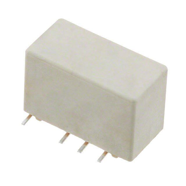
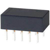
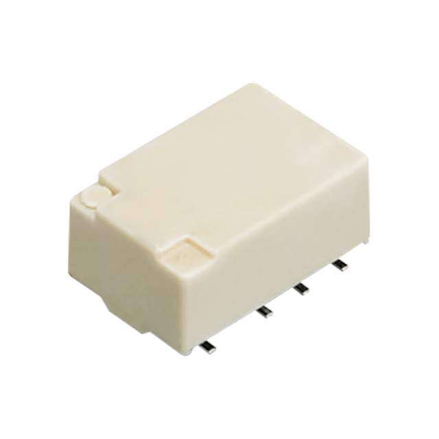
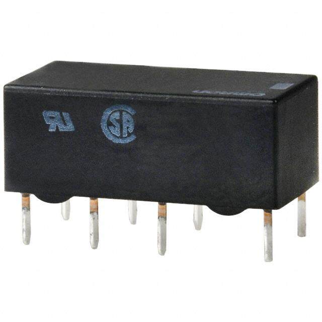
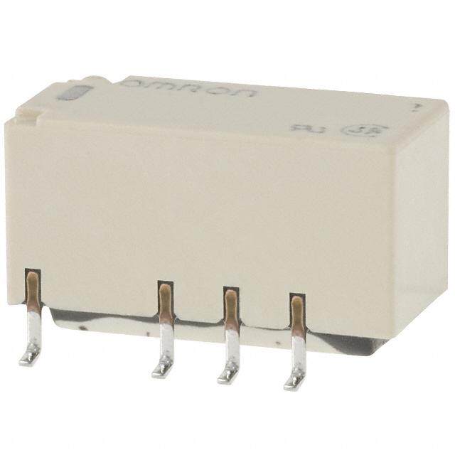
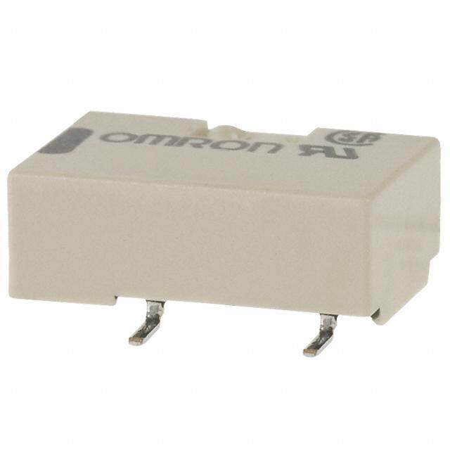
5 mm Low profile, TQ RELAYS 2 Form C and 2 A (surface- mount type) relays FEATURES 1.Flat compact size 8.A range of surface-mount types is 14.0 (L) × 9.0 (W) × 5.0 (H) mm also available .551 (L) × .354 (W) × .197 (H) inch SA: Low-profile surface-mount 2.Nominal operating power: terminal type High sensitivity of 140mW (2 Form SL: High connection reliability surface- C single side stable type) mount terminal type 3.Suitable for SMD automatic SS: Space saving surface-mount insertion (SA type) terminal type With a height of 5.6 mm .220 inch, the 9.M.B.B. contact types available RoHS compliant relays meet JIS C 0806 specifications. 4.DIL terminal array enables use of IC TYPICAL APPLICATIONS sockets 5.Low thermal electromotive force 1.Telephone-related equipment (approx. 5 μV) 2.Communications [approx. 2 μV (surface-mount type)] 3.Measurement equipment 6.Latching types also available 4.OA equipment 7.Self-clinching terminal also 5.Industrial machines available ORDERING INFORMATION TQ 2 Contact arrangement 2: 2 Form C Terminal shape Nil: Standard PC board terminal H: Self-clinching terminal SA: SA type SL: SL type SS: SS type Operating function Nil: Single side stable L: 1 coil latching L2: 2 coil latching MBB function Nil: Standard (B.B.M.) type 2M:2M.B.B. type Nominal coil voltage (DC)* 1.5 (SMD only), 3, 4.5, 5, 6, 9, 12, 24, 48V Packing style Nil:Tube packing X: Tape and reel (picked from 1/2/3/4/5-pin side) Z: Tape and reel packing (picked from the 6/7/8/9/10-pin side) Notes:1. *48 V coil type: Single side stable only 2. In case of 5 V transistor drive circuit, it is recommended to use 4.5 V type relay. –1– ASCTB14E 201407-T
TQ TYPES ■ Standard PC board terminal and self-clinching terminal 1. Standard (B.B.M.) type 1) Standard PC board terminal Contact Nominal coil Single side stable 1 coil latching 2 coil latching arrangement voltage Part No. Part No. Part No. 3 V DC TQ2-3V TQ2-L-3V TQ2-L2-3V 4.5 V DC TQ2-4.5V TQ2-L-4.5V TQ2-L2-4.5V 5 V DC TQ2-5V TQ2-L-5V TQ2-L2-5V 6 V DC TQ2-6V TQ2-L-6V TQ2-L2-6V 2 Form C 9 V DC TQ2-9V TQ2-L-9V TQ2-L2-9V 12 V DC TQ2-12V TQ2-L-12V TQ2-L2-12V 24 V DC TQ2-24V TQ2-L-24V TQ2-L2-24V 48 V DC TQ2-48V — — Standard packing (2 Form C): Tube: 50 pcs.; Case: 1,000 pcs. 2) Self-clinching terminal Contact Nominal coil Single side stable 1 coil latching 2 coil latching arrangement voltage Part No. Part No. Part No. 3 V DC TQ2H-3V TQ2H-L-3V TQ2H-L2-3V 4.5 V DC TQ2H-4.5V TQ2H-L-4.5V TQ2H-L2-4.5V 5 V DC TQ2H-5V TQ2H-L-5V TQ2H-L2-5V 6 V DC TQ2H-6V TQ2H-L-6V TQ2H-L2-6V 2 Form C 9 V DC TQ2H-9V TQ2H-L-9V TQ2H-L2-9V 12 V DC TQ2H-12V TQ2H-L-12V TQ2H-L2-12V 24 V DC TQ2H-24V TQ2H-L-24V TQ2H-L2-24V 48 V DC TQ2H-48V — — Note:Types (“-3” to the end of part No.) designed to withstand strong vibration caused, for example, by the use of terminal cutters, can also be ordered. However, please contact us if you need parts for use in low level load. 2. M.B.B. type 1) Standard PC board terminal Single side stable Contact arrangement Nominal coil voltage Part No. 3 V DC TQ2-2M-3V 4.5 V DC TQ2-2M-4.5V 5 V DC TQ2-2M-5V 2 Form C 6 V DC TQ2-2M-6V 9 V DC TQ2-2M-9V 12 V DC TQ2-2M-12V 24 V DC TQ2-2M-24V Standard packing: Tube: 50 pcs.; Case: 1,000 pcs. 2) Self-clinching terminal Single side stable Contact arrangement Nominal coil voltage Part No. 3 V DC TQ2H-2M-3V 4.5 V DC TQ2H-2M-4.5V 5 V DC TQ2H-2M-5V 2 Form C 6 V DC TQ2H-2M-6V 9 V DC TQ2H-2M-9V 12 V DC TQ2H-2M-12V 24 V DC TQ2H-2M-24V Standard packing: Tube: 50 pcs.; Case: 1,000 pcs. Notes:1.Latching types are available by request. Please consult us for details. 2.UL/CSA approved (UL file No.:E 43149, CSA file No.: LR26550) 3.Types (“-1” to the end of part No.) designed to withstand strong vibration caused, for example, by the use of terminal cutters, can also be ordered. However, please contact us if you need parts for use in low level load and low thermal power. –2– ASCTB14E 201407-T
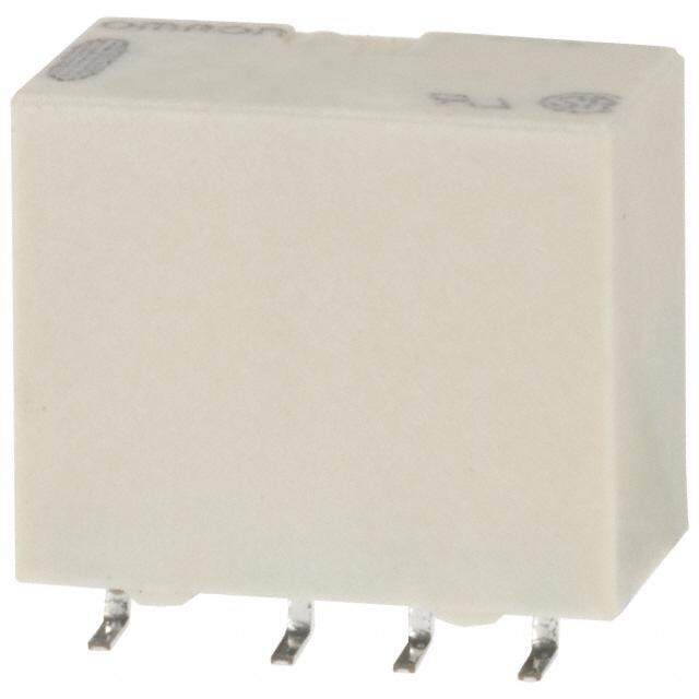
TQ ■ Surface-mount terminal 1) Tube packing Contact Nominal coil Single side stable 1 coil latching 2 coil latching arrangement voltage Part No. Part No. Part No. 1.5 V DC TQ2S(cid:2)-1.5V TQ2S(cid:2)-L-1.5V TQ2S(cid:2)-L2-1.5V 3 V DC TQ2S(cid:2)-3V TQ2S(cid:2)-L-3V TQ2S(cid:2)-L2-3V 4.5 V DC TQ2S(cid:2)-4.5V TQ2S(cid:2)-L-4.5V TQ2S(cid:2)-L2-4.5V 5 V DC TQ2S(cid:2)-5V TQ2S(cid:2)-L-5V TQ2S(cid:2)-L2-5V 2c 6 V DC TQ2S(cid:2)-6V TQ2S(cid:2)-L-6V TQ2S(cid:2)-L2-6V 9 V DC TQ2S(cid:2)-9V TQ2S(cid:2)-L-9V TQ2S(cid:2)-L2-9V 12 V DC TQ2S(cid:2)-12V TQ2S(cid:2)-L-12V TQ2S(cid:2)-L2-12V 24 V DC TQ2S(cid:2)-24V TQ2S(cid:2)-L-24V TQ2S(cid:2)-L2-24V 48 V DC TQ2S(cid:2)-48V — — (cid:2): For each surface-mounted terminal identification, input the following letter. SA type: A, SL type: L, SS type: S Standard packing: Tube: 50 pcs.; Case: 1,000 pcs. 2) Tape and reel packing Contact Nominal coil Single side stable 1 coil latching 2 coil latching arrangement voltage Part No. Part No. Part No. 1.5 V DC TQ2S(cid:2)-1.5V-Z TQ2S(cid:2)-L-1.5V-Z TQ2S(cid:2)-L2-1.5V-Z 3 V DC TQ2S(cid:2)-3V-Z TQ2S(cid:2)-L-3V-Z TQ2S(cid:2)-L2-3V-Z 4.5 V DC TQ2S(cid:2)-4.5V-Z TQ2S(cid:2)-L-4.5V-Z TQ2S(cid:2)-L2-4.5V-Z 5 V DC TQ2S(cid:2)-5V-Z TQ2S(cid:2)-L-5V-Z TQ2S(cid:2)-L2-5V-Z 2 Form C 6 V DC TQ2S(cid:2)-6V-Z TQ2S(cid:2)-L-6V-Z TQ2S(cid:2)-L2-6V-Z 9 V DC TQ2S(cid:2)-9V-Z TQ2S(cid:2)-L-9V-Z TQ2S(cid:2)-L2-9V-Z 12 V DC TQ2S(cid:2)-12V-Z TQ2S(cid:2)-L-12V-Z TQ2S(cid:2)-L2-12V-Z 24 V DC TQ2S(cid:2)-24V-Z TQ2S(cid:2)-L-24V-Z TQ2S(cid:2)-L2-24V-Z 48 V DC TQ2S(cid:2)-48V-Z — — (cid:2): For each surface-mounted terminal identification, input the following letter. SA type: A, SL type: L, SS type: S Standard packing: Tape and reel: 500 pcs.; Case: 1,000 pcs. Note: Tape and reel packing symbol “-Z” is not marked on the relay. “X” type tape and reel packing (picked from 1/2/3/4-pin side) is also available. RATING ■ Standard PC board terminal and self-clinching terminal 1. Coil data [Standard (B.B.M.) type] 1) Single side stable (2 Form C) Nominal operating Nominal coil Pick-up voltage Drop-out voltage Coil resistance Nominal operating Max. applied voltage voltage (at 20°C 68°F) (at 20°C 68°F) [±10%] c(autr r2e0n°tC 68°F) [±10%] (at 20°C 68°F) power (at 20°C 68°F) 3 V DC 46.7 mA 64.3 Ω 4.5 V DC 31.1 mA 144.6 Ω 5 V DC 28.1 mA 178 Ω 6 V DC 75%V or less of 10%V or more of 23.3 mA 257 Ω 140 mW nom15in0a%l vVo lotaf ge 9 V DC nominal voltage* nominal voltage* 15.5 mA 579 Ω 12 V DC (Initial) (Initial) 11.7 mA 1,028 Ω 24 V DC 8.3 mA 2,880 Ω 200 mW 48 V DC 6.25 mA 7,680 Ω 300 mW 120%V of nominal voltage 2) 1 coil latching (2 Form C) Nominal operating Nominal coil Set voltage Reset voltage Coil resistance Nominal operating Max. applied voltage voltage (at 20°C 68°F) (at 20°C 68°F) [±10%] c(autr r2e0n°tC 68°F) [±10%] (at 20°C 68°F) power (at 20°C 68°F) 3 V DC 33.3 mA 90 Ω 4.5 V DC 22.2 mA 202.5 Ω 56 VV DDCC n7o5m%inVa ol rv oleltsasg oef* n7o5m%inVa ol rv oleltsasg oef* 2106 . 7 mmAA 235600 ΩΩ 100 mW 150%V of nominal voltage 9 V DC (Initial) (Initial) 11.1 mA 810 Ω 12 V DC 8.3 mA 1,440 Ω 24 V DC 6.3 mA 3,840 Ω 150 mW –3– ASCTB14E 201407-T
TQ 3) 2 coil latching (2 Form C) Nominal operating Coil resistance Nominal operating Novmoilntaagl ecoil (aSt e2t0 v°Col t6a8g°eF ) (Raet s2e0t° Cvo 6lt8a°gFe) [±10%] c(autr r2e0n°tC 68°F) [±10%] (at 20°C 68°F) power Ma(xa. ta 2p0p°liCe d6 8vo°Flt)age Set coil Reset coil Set coil Reset coil Set coil Reset coil 3 V DC 66.7 mA 66.7 mA 45 Ω 45 Ω 4.5 V DC 44.4 mA 44.4 mA 101.2 Ω 101.2 Ω 5 V DC 40 mA 40 mA 125 Ω 125 Ω 150%V of 6 V DC 75%V or less of 75%V or less of 33.3 mA 33.3 mA 180 Ω 180 Ω 200 mW 200 mW nominal voltage nominal voltage* nominal voltage* 9 V DC (Initial) (Initial) 22.2 mA 22.2 mA 405 Ω 405 Ω 12 V DC 16.7 mA 16.7 mA 720 Ω 720 Ω 24 V DC 12.5 mA 12.5 mA 1,920 Ω 1,920 Ω 300 mW 300 mW 120%V of nominal voltage [M.B.B. type] Nominal operating Nominal coil Pick-up voltage Drop-out voltage Coil resistance Nominal operating Max. applied voltage voltage (at 20°C 68°F) (at 20°C 68°F) [±10%] c(autr r2e0n°tC 68°F) [±10%] (at 20°C 68°F) power (at 20°C 68°F) 3 V DC 66.7 mA 45 Ω 4.5 V DC 44.4 mA 101 Ω 5 V DC 80%V or less of 10%V or more of 40 mA 125 Ω 6 V DC nominal voltage* nominal voltage* 33.3 mA 180 Ω 200 mW 150%V of nominal voltage 9 V DC (Initial) (Initial) 22.2 mA 405 Ω 12 V DC 16.7 mA 720 Ω 24 V DC 8.3 mA 2,880 Ω *Pulse drive (JIS C 5442-1986) 2. Specifications Characteristics Item Specifications Arrangement 2 Form C, 2 Form D (M.B.B.) Contact Initial contact resistance, max. Max. 50mΩ (By voltage drop 6 V DC 1A) Contact material Ag+Au clad Nominal switching capacity 1 A 30 V DC, 0.5 A 125 V AC (resistive load) Max. switching power 30 W (DC), 62.5 V A (AC) (resistive load) Max. switching voltage 110 V DC, 125 V AC Max. switching current 1 A Rating Min. switching capacity (Reference value)*1 10μA 10mV DC Standard (B.B.M) type: 140 mW (3 to 12 V DC), 200 mW (24 V DC), 300 mW (48 V DC) Single side stable Nominal M.B.B. type: 200 mW operating power 1 coil latching 100 mW (3 to 12 V DC), 150 mW (24 V DC) 2 coil latching 200 mW (3 to 12 V DC), 300 mW (24 V DC) Min. 1,000MΩ (at 500V DC) Insulation resistance (Initial) Measurement at same location as “Initial breakdown voltage” section. Standard (B.B.M) type: 750 Vrms for 1min. (Detection current: 10 mA), Between open contacts Breakdown M.B.B. type: 300 Vrms for 1 min. (Detection current: 10 mA) Electrical voltage (Initial) Between contact and coil 1,000 Vrms for 1min. (Detection current: 10 mA) characteristics Between contact sets 1,000 Vrms for 1min. (Detection current: 10 mA) Temperature rise (at 20°C 68°F) Max. 50°C (By resistive method, nominal coil voltage applied to the coil; contact carrying current: 1A.) Operate time [Set time] (at 20°C 68°F) Max. 3 ms [Max. 3 ms] (Nominal coil voltage applied to the coil, excluding contact bounce time.) Release time [Reset time] (at 20°C 68°F) Max. 3 ms [Max. 3 ms] (Nominal coil voltage applied to the coil, excluding contact bounce time.) (without diode) Shock Functional Min. 490 m/s2 (Half-wave pulse of sine wave: 11 ms; detection time: 10μs.) Mechanical resistance Destructive Min. 980 m/s2 (Half-wave pulse of sine wave: 6 ms.) characteristics Vibration Functional 10 to 55 Hz at double amplitude of 3 mm (Detection time: 10μs.) resistance Destructive 10 to 55 Hz at double amplitude of 5 mm Mechanical (at 180 cpm) Standard (B.B.M) type: Min. 108, M.B.B. type: Min. 107 Expected life Standard (B.B.M) type: Min. 2×10⁵ (1 A 30 V DC resistive), Min. 105 (0.5 A 125 V AC resistive) Electrical (at 20 cpm) M.B.B. type: Min. 105 (1 A 30 V DC resistive) Standard (B.B.M) type: Ambient temperature: –40°C to +70°C –40°F to +158°F; Conditions for operation, transport and Humidity: 5 to 85% R.H. (Not freezing and condensing at low temperature) Conditions storage*2 M.B.B. type: Ambient temperature: –40°C to +50°C –40°F to +122°F; Humidity: 5 to 85% R.H. (Not freezing and condensing at low temperature) Max. operating speed (at rated load) 20 cpm Unit weight Approx. 1.5 g .053 oz Notes:*1 This value can change due to the switching frequency, environmental conditions, and desired reliability level, therefore it is recommended to check this with the actual load. TX/TX-S/TX-D relay AgPd contact type are available for low level load switching (10V DC, 10mA max. level). *2 Refer to “AMBIENT ENVIRONMENT” in GENERAL APPLICATION GUIDELINES. –4– ASCTB14E 201407-T
TQ ■ Surface-mount terminal 1. Coil data 1) Single side stable Nominal operating Nominal coil Pick-up voltage Drop-out voltage Coil resistance Nominal operating Max. applied voltage voltage (at 20°C 68°F) (at 20°C 68°F) (at 2c0u°rCre n6t8 °F) [±10%] (at 20°C 68°F) power (at 20°C 68°F) 1.5 V DC 93.8 mA 16 Ω 3 V DC 46.7 mA 64.3 Ω 4.5 V DC 31 mA 145 Ω 5 V DC 28.1 mA 178 Ω 140 mW 150%V of 6 V DC 75%V or less of 10%V or more of 23.3 mA 257 Ω nominal voltage nominal voltage* nominal voltage* 9 V DC (Initial) (Initial) 15.5 mA 579 Ω 12 V DC 11.7 mA 1,028 Ω 24 V DC 8.3 mA 2,880 Ω 200 mW 48 V DC 6.3 mA 7,680 Ω 300 mW 120%V of nominal voltage 2) 1 coil latching Nominal operating Nominal coil Set voltage Reset voltage Coil resistance Nominal operating Max. applied voltage voltage (at 20°C 68°F) (at 20°C 68°F) (at 2c0u°rCre n6t8 °F) [±10%] (at 20°C 68°F) power (at 20°C 68°F) 1.5 V DC 46.9 mA 32 Ω 3 V DC 23.3 mA 128.6 Ω 4.5 V DC 15.6 mA 289.3 Ω 5 V DC 75%V or less of 75%V or less of 14 mA 357 Ω 70 mW 150%V of nominal voltage* nominal voltage* 6 V DC (Initial) (Initial) 11.7 mA 514 Ω nominal voltage 9 V DC 7.8 mA 1,157 Ω 12 V DC 5.8 mA 2,057 Ω 24 V DC 4.2 mA 5,760 Ω 100 mW 3) 2 coil latching Nominal operating Coil resistance Nominal operating Novmoilntaagl ecoil (aSt e2t0 v°Col t6a8g°eF ) (Raet s2e0t° Cvo 6lt8a°gFe) (at 2c0u°rCre n6t8 °F) [±10%] (at 20°C 68°F) power Ma(xa. ta 2p0p°liCe d6 8vo°Flt)age Set coil Reset coil Set coil Reset coil Set coil Reset coil 1.5 V DC 93.8 mA 93.8 mA 16 Ω 16 Ω 3 V DC 46.7 mA 46.7 mA 64.3 Ω 64.3 Ω 4.5 V DC 31 mA 31 mA 145 Ω 145 Ω 5 V DC 75%V or less of 75%V or less of 28.1 mA 28.1 mA 178 Ω 178 Ω 140 mW 140 mW 150%V of nominal voltage* nominal voltage* 6 V DC (Initial) (Initial) 23.3 mA 23.3 mA 257 Ω 257 Ω nominal voltage 9 V DC 15.5 mA 15.5 mA 579 Ω 579 Ω 12 V DC 11.7 mA 11.7 mA 1,028 Ω 1,028 Ω 24 V DC 8.3 mA 8.3 mA 2,880 Ω 2,880 Ω 200 mW 200 mW *Pulse drive (JIS C 5442-1986) –5– ASCTB14E 201407-T
TQ 2. Specifications Characteristics Item Specifications Arrangement 2 Form C Contact Initial contact resistance, max. Max. 75 mΩ (By voltage drop 6 V DC 1A) Contact material AgNi type+Au clad Nominal switching capacity 2 A 30 V DC, 0.5 A 125 V AC (resistive load) Max. switching power 60 W (DC), 62.5 VA (AC) (resistive load) Max. switching voltage 220 V DC, 125 V AC Max. switching current 2 A Rating Min. switching capacity (Reference value)*1 10μA 10mV DC Single side stable 140 mW (1.5 to 12 V DC), 200 mW (24 V DC), 300 mW (48 V DC) Nominal operating 1 coil latching 70 mW (1.5 to 12 V DC), 100 mW (24 V DC) power 2 coil latching 140 mW (1.5 to 12 V DC), 200 mW (24 V DC) Min. 1,000MΩ (at 500V DC) Insulation resistance (Initial) Measurement at same location as “Initial breakdown voltage” section. Between open contacts 1,000 Vrms for 1 min. (Detection current: 10 mA) Breakdown voltage Between contact and coil 1,500 Vrms for 1 min. (Detection current: 10 mA) (Initial) Between contact sets 1,500 Vrms for 1 min. (Detection current: 10 mA) Electrical Surge breakdown Between open contacts 1,500 V (10×160μs) (FCC Part 68) characteristics voltage (Initial) Between contacts and coil 2,500 V (2×10μs) (Bellcore) Temperature rise (at 20°C 68°F) Max. 50°C (By resistive method, nominal coil voltage applied to the coil; contact carrying current: 2A.) Operate time [Set time] (at 20°C 68°F) Max. 4 ms [Max. 4 ms] (Nominal coil voltage applied to the coil, excluding contact bounce time.) Release time [Reset time] (at 20°C 68°F) Max. 4 ms [Max. 4 ms] (Nominal coil voltage applied to the coil, excluding contact bounce time.) (without diode) Functional Min. 750 m/s2 (Half-wave pulse of sine wave: 6 ms; detection time: 10μs.) Shock resistance Mechanical Destructive Min. 1,000 m/s2 (Half-wave pulse of sine wave: 6 ms.) characteristics Functional 10 to 55 Hz at double amplitude of 3.3 mm (Detection time: 10μs.) Vibration resistance Destructive 10 to 55 Hz at double amplitude of 5 mm Mechanical Min. 108 (at 180 cpm) Expected life Min. 105 (2 A 30 V DC resistive), Min. 2×10⁵ (1 A 30 V DC resistive), Electrical Min. 105 (0.5 A 125 V AC resistive) (at 20 cpm) Ambient temperature: Conditions for operation, transport and storage*2 –40°C to +85°C –40°F to +185°F, Max. –40°C to +70°C (2A) Max. –40°F to +158°F (2A); Conditions Humidity: 5 to 85% R.H. (Not freezing and condensing at low temperature) Max. operating speed (at rated load) 20 cpm Unit weight Approx. 2 g .071 oz Notes:*1 This value can change due to the switching frequency, environmental conditions, and desired reliability level, therefore it is recommended to check this with the actual load. (TX/TX-S/TX-D relay AgPd contact type are available for low level load switching [10V DC, 10mA max. level]) *2 Refer to “AMBIENT ENVIRONMENT” in GENERAL APPLICATION GUIDELINES. –6– ASCTB14E 201407-T
TQ REFERENCE DATA ■ Standard PC board terminal and self-clinching terminal 1. Maximum switching capacity 2. Life curve 3. Mechanical life Tested sample: TQ2-12V, 10 pcs. 100 V Switching current, A1000....0543 DACC llooaadd ((ccoossϕϕ==11)) ×No. of operations, 104 10100 13205 V V D ACC r eressisistitvivee l oloaadd ainst the rated voltage, % 987654000000 PDircokp--uopu tv ovlotaltgaege MMainx.. ag 30 Max. 0.2 atio 20 R 10 Min. 0 30 100 200 0 0.5 1.0 10 100 1,000 10,000 Switching voltage,V Switching current, A No. of operations, ×104 4.-(1) Electrical life (DC load) 4.-(2) Electrical life (AC load) Tested sample: TQ2-12V, 6 pcs. Tested sample: TQ2-12V, 6 pcs. Condition: 1 A 30 V DC resistive load, 20 cpm Condition: 0.5 A 125 V AC resistive load, 20 cpm Change of pick-up and drop-out voltage Change of contact resistance Change of pick-up and drop-out voltage Ratio against the rated voltage, %V109876543210000000000 Pick-up voDltraogpe-out voltage MMMMaiainnxx.... ΩContact resistance, m109876543210000000000 MMainx.. Ratio against the rated voltage, %V109876543210000000000 PDircokp-u-opu vt ovlotaltgaege MMMMaiainnxx.... 0 5 10 15 20 0 5 10 15 20 0 5 10 No. of operations, ×104 No. of operations, ×104 No. of operations, ×104 5. Coil temperature rise (2C) 6. Ambient temperature characteristics Tested sample: TQ2-12V Tested sample: TQ2-12V, 5 pcs. Measured portion: Inside the coil Change of contact resistance Ambient temperature: 30°C 86°F % ΩContact resistance, m109876540000000 Max. °Temperature rise, C 7654300000 Nom32i 4nto aV l1 Dc2oC Vil tvDyopCl110eta tAAAgypee -40 -20 0Variation ratio,12340000 2-Dv10or0lot4ap0g-oePuiAtct6ekm0m-ubppixxee 8rvna0ott lutareg,e°C 30 Min. 20 -20 20 10 -30 10 0 -40 0 5 10 100 110 120 130 140 150 No. of operations, ×104 Coil applied voltage, %V 7.-(1) High-frequency characteristics 7.-(2) High-frequency characteristics 8. Malfunctional shock (single side stable) (Isolation) (Insertion loss) Tested sample: TQ2-12V, 6 pcs. Z,Z XX, Y Dcoenednietiorgnized dB YY, 980m/s2 Energized condition on, dB100 n loss, 98X0m/s2 980Zm/s2 Isolati nsertio01..80 I 50 0.6 980m/s2 980m/s2 , , 0.4 Z X 0.2 9,80m/s2 Y 10 100 1,000 0 10 100 1,000 Frequency, MHz Frequency, MHz –7– ASCTB14E 201407-T
TQ 9.-(1) Influence of adjacent mounting 9.-(2) Influence of adjacent mounting 10. Contact reliability (1 mA 5 V DC resistive load) Tested sample: TQ2-12V Condition: Detection level 10 W F(t), % % % 99.9 nge, 10 Pick-up voltage ON ON nge, 10 Pick-up voltage ON 9959..00 ha ha 70.0 e of c 0 e of c 0 ON 3500..00 at–10 at–10 R ON R ON 10.0 nge, % 10 Drop-out voltage OFFOFF nge, % 10 Drop-out voltage OFF 25..00 ate of cha–100 OFF ate of cha–100 OFF 001...250 9 mμ 5 == % 2 2 . .7 1r ×e 5 1l ia 0 b 7 i l i7ty.6 li×m1i0t 6= R R (Weibull probability paper) OFF 0.1 0 5 0 5 1.0 10 100 .197 .197 Inter-relay distance , mminch Inter-relay distance , mminch No. of operations, ×106 11. Actual load test (35 mA 48 V DC wire spring relay load) Circuit Change of pick-up and drop-out voltage Change of contact resistance 20Hz 100 100 V age, %8900 Ωm 8900 5D7 CV 220Ω against the rated volt3456700000 PDircokp-u-opu vt ovlotaltgaege MMainx.. Contact resistance, 3456700000 MMainx.. 220Ω Ratio 1200 MMainx.. 1200 Wire spring relay Circuit diagram 0 0 10 20 30 40 50 10 20 30 40 50 No. of operations, ×104 No. of operations, ×104 12. 0.1 A 53 V DC resistive load test Change of pick-up and drop-out voltage Change of contact resistance 100 100 V d voltage, %789000 Pick-up voltage MMainx.. Ωance, m 789000 Ratio against the rate123456000000 Drop-out voltage MMainx.. Contact resist 123456000000 MMainx.. 0 500 1,000 1,500 2,000 0 500 1,000 1,500 2,000 No. of operations, ×104 No. of operations, ×104 13. Distribution of M.B.B. time Tested sample: TQ2-2M-5V, 85 pcs. 60 60 Terminal −xN:os. 21-30-54.:6 O μNs Terminal N−xo:s. 2-731-4.6: OμFsF 50 M3σinn-.1:: 2136 3μ.8s μs 50 3Mσinn-.1:: 1172 7μ.1s μs Max.:243 μs 41 Max.:187 μs 40 Terminal −xN:os. 71-81-59.:6 O μNs 40 35 Terminal N−xo:s. 7-880-9.7: OμFsF 30 30 3Mσinn-.1:: 3156 7μ.3s μs 30 31 27 3Mσinn-.1:: 2195 6μ.7s μs 26 Max.:254 μs Max.:298 μs 20 19 21 19 17 20 15 11 12 10 10 7 6 10 4 2 4 1 2 0 10 50 100 150 200 250 300 μs min. 0 10 50 100 150 200 250 300 μs min. ~ ~ ~ ~ ~ ~ ~ ~ ~ ~ ~ ~ ~ ~ 50 100 150 200 250 300 350 μs max. 50 100 150 200 250 300 350 μs max. –8– ASCTB14E 201407-T
TQ ■ Surface-mount terminal 1. Maximum switching capacity 2. Life curve 3. Mechanical life (mounting by IRS method) Tested sample: TQ2SA-12V, 10 pcs. 100 V A23..00 410100 age, % 8900 Switching current, 0001....3450 AC resistive load DC resistive load ×No. of operations, 532000 1re2s5isVt ivAeC l oad 3re0sVis DtivCe load o against the rated volt 3456700000 PDircokp--uopu vt ovlotaltgaege MMMaainxx... 0.2 10 ati 20 R Min. 10 0 0 0 20 30 50 100 200300 1.0 2.0 IRS1 10 100 1,000 10,000 Contact voltage, V Switching current, A No. of operations, ×104 4.-(1) Electrical life (2 A 30 V DC resistive load) 4.-(2) Electrical life (0.5 A 125 V AC resistive load) Tested sample: TQ2SA-12V, 6 pcs. Tested sample: TQ2SA-12V, 6 pcs Operating speed: 20 cpm Operating speed: 20 cpm Change of pick-up and drop-out voltage Change of contact resistance Change of pick-up and drop-out voltage (mounting by IRS method) (mounting by IRS method) (mounting by IRS method) 100 100 100 V V % 90 90 % 90 Ratio against the rated voltage, 1234567800000000 PDircokp--uopu vt ovlotaltgaege MMMMaiiannxx.... ΩContact resistance, m1234567800000000 MMainx.. Ratio against the rated voltage, 1234567800000000 PDircokp--uopu vt ovlotaltgaege MMMMaiiannxx.... 0 0 0 IRS 1 2 3 4 5 6 7 8 9 10 IRS 1 2 3 4 5 6 7 8 9 10 IRS 1 2 3 4 5 6 7 8 9 10 No. of operations, ×104 No. of operations, ×104 No. of operations, ×104 5. Coil temperature rise 6. Operate/release time Tested sample: TQ2SA-12V, 6 pcs. Tested sample: TQ2SA-12V, 6 pcs. Change of contact resistance Point measured: Inside the coil (mounting by IRS method) Ambient temperature: 25°C 77°F 100 70 5 Coil voltage 2A Operate time ΩContact resistance, m34567890000000 MMainx.. °Temperature rise, C 3624500000 DDCC 1428VV ttyyppee 020AAA erate and release time, ms 243 MMainx.. Release time p 20 O Max. 10 1 Min. 10 0 0 0 IRS 1 2 3 4 5 6 7 8 9 10 100 110 120 130 140 150 70 80 90 100 110 120 No. of operations, ×104 Coil applied voltage, %V Coil applied voltage, %V 7. Ambient temperature characteristics 8.-(1) High-frequency characteristics 8.-(2) High-frequency characteristics Tested sample: TQ2SA-12V, 5 pcs. (Isolation) (Insertion loss) % e, 40 g n a B –40 –20 0Rate of ch 22004A0Pmicbki6e-D0unprto vp8o-0xoltuatg veoltage Isolation, dB100 nsertion loass, d 10..08 temperature, °C 50 I 0.6 –20 0.4 –40 0.2 10 100 1,000 10 100 1,000 Frequency, MHz Frequency, MHz –9– ASCTB14E 201407-T
TQ 9. Malfunctional shock (single side stable) 10.-(1) Influence of adjacent mounting 10.-(2) Influence of adjacent mounting Tested sample: TQ2SA-12V, 6 pcs Tested sample: TQ2SA-12V, 5 pcs. Tested sample: TQ2SA-12V, 6 pcs. 10YY0Z'0'mX/Zs2XX1'000m/s2Y DcEcoonennee1ddrngZ0iiettiii0'ozor0gennmidze/sd2 Rate of change, %–11000 Pick-up voltage ONONON Rate of change, %–11000 Pick-up voltage OONNON % % OFF 1000mZ/s2 Y1'000m/s2 1X00'0m/s2 Rate of change, –11000 Drop-out voltage OFOFFOFFF Rate of change, –11000 Drop-out voltage OFFOFF 0 1 2 3 4 5 6 0 1 2 3 4 5 6 .039.079.118.157.197.236 .039.079.118.157.197.236 Inter-relay distance , mminch Inter-relay distance , mminch 11. Pulse dialing test (35 mA 48 V DC wire spring relay load) Change of pick-up and drop-out voltage Change of contact resistance Tested sample: TQ2SA-12V, 6 pcs. (mounting by IRS method) (mounting by IRS method) Circuit V100 100 % e, 90 90 4–+8 V DC0μ.0F8445588 ΩΩ0μ.0F8 32TQ-SreMlaDy o against the rated voltag 345678000000 PDircokp--uopu vt ovlotaltgaege MMMaianxx... ΩContact resistance, m 345678000000 MMainx.. Wire spring relay Rati 20 Min. 20 10 10 0 0 IRS 10 20 30 40 50 IRS 10 20 30 40 50 No. of operations, ×104 No. of operations, ×104 DIMENSIONS (mm inch) The CAD data of the products with a CAD Data mark can be downloaded from: http://industrial.panasonic.com/ac/e/ 1. Standard PC board terminal and Self-clinching terminal CAD Data External dimensions PC board pattern (Bottom view) Standard PC board terminal (4.75) 14 9 2.1.5040 1.400.106 1100--1.0.039 d idai.a. (.187) .551 .354 .1975+−3+−..0000.10..54268 2.1.50407.3.6020 .138 0.25 0.5 0.25 .010 .21.0504 .020 7.3.6020 .010 Tolerance: ±0.1 ±.004 Self-clinching terminal Schematic (Bottom view) Single side stable 1-coil latching 2-coil latching (4.75) 14 9 (.187) .551 .354 .1975+−+−..000010..4268 + 1 2 3 4 5 − 1 2 3 4 5 +1 2 3 4 −5 3.5 .138 + − − + .00.1205 2.54 0.0.520 7.62 .00.1205 10 9 8 7 6 10 9 8 7 6 10 9 8 7 6 .100 .300 Direction indication Direction indication Direction indication General tolerance: ±0.3 ±.012 (Deenergized condition) (Reset condition) (Reset condition) –10– ASCTB14E 201407-T
TQ 2. Surface-mount terminal CAD Data Type External dimensions (General tolerance: ±0.3 ±.012) Suggested mounting pad (Top view) (Tolerance: ±0.1 ±.004) .51541 .3954 .0319 .21.0504 SA type 5.2.620 .41.993 .00.1205 .21.1964 9.56 7.62 .376 2.54 0.2 .300 .100 0.0.520 .008 .41513.5±±.002.50 .51541 .3954 .0319 .21.0504 4.9 0.25 2.94 Max.7.5 .193 .010 .116 SL type .295 9.56 2.1.5040 .00.250 11.7.35.06±020.5 .376 .453±.020 .51541 .3954 .0391 2.1.5040 SS type Max..72.955 .41.993 .00.1205 1.0.8742 8.46 2.1.5040 0.0.520 9.7.33.±60020.5 .333 .366±.020 Schematic (Top view) Single side stable 1-coil latching 2-coil latching −10 9 8 7 6 +10 9 8 7 6 10 9 8 7 6 + − + − + − 1 2 3 4 5 1 2 3 4 5 1 2 3 4 5 Direction indication Direction indication Direction indication (Deenergized condition) (Reset condition) (Reset condition) NOTES 1. Packing style (ii) SL, SS type 2. Automatic insertion 1) The relay is packed in a tube with the mm inch To maintain the internal function of the relay orientation mark on the left side, as relay, the chucking pressure should not shown in the figure below. .001.46 R(Ze tlaypy ep)olarity .b01a5.r59+ + 00.00.014ddiaia..2.0.079 .41.507 1.547..1650.6795 eCxhcuecekdin tgh ep rveaslsuuerse b ine lothwe. direction A: Orientation (indicates PIN No.1) stripe 11.5 9.8 N {1 kgf} or less 7.8±0.2 .453 Chucking pressure in the direction B: .307T±Q.00-8SMD relays 1.663.00 (1.14208..341 .92445.0±.±001.23 9.8 N {1 kgf} or less Note) *SS type .398)* Chucking pressure in the direction C: Stopper (gray) Stopper (green) Tape coming out direction 9.8 N {1 kgf} or less 2) Tape and reel packing (surface-mount (2) Dimensions of plastic reel terminal type) mm inch A C B (1) Tape dimensions 21 dia. (i) SA type .827 dia. mm inch 2.0 .079 Relay polarity bar 2.0 4.0 1.75 Please chuck the portion. .001.46 (Z type) .015.95+ + 00.00.014ddiaia...079 .157 1.547..65069 38.01±51d0i±a.0.39dia. AInv oaiddd cithiounc,k einxgc ethsesi vcee nctheur cokfi nthge p rreelsasyu.re 11.5 .453 330±2dia. to the pinpoint of the relay should be 12.992±.079dia. .2468.3±.±000.82 TQ-SMD relays 1.663.00 1.428.34 .92445.0±.±001.23 13 dia. avoided. Tape coming out direction .512 dia. For general cautions for use, please refer to the “Cautions for use of Signal Relays” or “General Application Guidelines”. –11– ASCTB14E 201407-T
Mouser Electronics Authorized Distributor Click to View Pricing, Inventory, Delivery & Lifecycle Information: P anasonic: TQ2-L2-3V TQ2-4.5V TQ2-L2-5V TQ2-5V TQ2-12V TQ2-24V TQ4-24V TQ2SS-1.5V TQ4-6V TQ4-L2-12V TQ2-3V TQ4-3V TQ4-4.5V TQ2-L-5V TQ2H-5V TQ4-5V TQ2-6V TQ2-9V TQ2-L2-12V TQ4-12V TQ2-L2-24V TQ2-L-3V TQ4-L2-5V TQ2-L2-4.5V TQ2-L2-6V TQ2-L2-9V TQ2-48V TQ2-L-4.5V TQ4-L2-24V