ICGOO在线商城 > 集成电路(IC) > 接口 - 驱动器,接收器,收发器 > TUSB1310AZAY
 Datasheet下载
- 型号: TUSB1310AZAY
- 制造商: Texas Instruments
- 库位|库存: xxxx|xxxx
- 要求:
| 数量阶梯 | 香港交货 | 国内含税 |
| +xxxx | $xxxx | ¥xxxx |
查看当月历史价格
查看今年历史价格
TUSB1310AZAY产品简介:
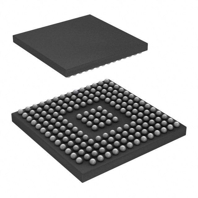
ICGOO电子元器件商城为您提供TUSB1310AZAY由Texas Instruments设计生产,在icgoo商城现货销售,并且可以通过原厂、代理商等渠道进行代购。 TUSB1310AZAY价格参考。Texas InstrumentsTUSB1310AZAY封装/规格:接口 - 驱动器,接收器,收发器, 收发器 1/1 USB 3.0 175-NFBGA(12x12)。您可以下载TUSB1310AZAY参考资料、Datasheet数据手册功能说明书,资料中有TUSB1310AZAY 详细功能的应用电路图电压和使用方法及教程。
TUSB1310AZAY 是德州仪器(Texas Instruments)生产的一款接口器件,属于USB 3.0超高速线性红驱动器(redriver)芯片。该器件主要用于增强USB 3.0信号的传输质量,适用于需要长距离或高速传输的应用场景。

典型应用场景包括:

1. 主板与扩展卡:用于PC主板或PCIe扩展卡上的USB 3.0接口,提升信号完整性,延长有效传输距离。

2. 外设扩展坞(Docking Station):在多接口扩展坞中,作为信号中继器,确保USB 3.0高速数据传输的稳定性。

3. 工业与嵌入式系统:在工业控制、嵌入式设备中,用于改善高速信号在背板或长线缆中的传输性能。

4. 消费类电子产品:如高性能存储设备、视频采集设备等,确保高速数据传输过程中信号不失真。

该芯片支持USB 3.0 SuperSpeed(5Gbps)速率,具备可配置均衡与输出幅度调节功能,适用于各种高速接口设计中的信号调理。
| 参数 | 数值 |
| 产品目录 | 集成电路 (IC)半导体 |
| 描述 | IC TXRX USB 3.0 SGL 175NFBGAUSB 接口集成电路 SuperSpeed USB Xcvr |
| 产品分类 | |
| 品牌 | Texas Instruments |
| 产品手册 | |
| 产品图片 |
|
| rohs | 符合RoHS无铅 / 符合限制有害物质指令(RoHS)规范要求 |
| 产品系列 | 接口 IC,USB 接口集成电路,Texas Instruments TUSB1310AZAY- |
| 数据手册 | |
| 产品型号 | TUSB1310AZAY |
| 产品种类 | USB 接口集成电路 |
| 供应商器件封装 | 175-NFBGA(12x12) |
| 其它名称 | 296-28131 |
| 包装 | 托盘 |
| 协议 | USB 3.0 |
| 双工 | - |
| 商标 | Texas Instruments |
| 安装类型 | 表面贴装 |
| 安装风格 | SMD/SMT |
| 封装 | Tray |
| 封装/外壳 | 175-LFBGA |
| 封装/箱体 | nFBGA-175 |
| 工作温度 | -40°C ~ 85°C |
| 工作电源电压 | 1.1 V, 1.8 V, 3.3 V |
| 工作电源电流 | 1 uA |
| 工厂包装数量 | 160 |
| 接收器滞后 | 270mV |
| 数据速率 | - |
| 最大工作温度 | + 70 C |
| 最小工作温度 | 0 C |
| 标准 | USB 3.0 |
| 标准包装 | 160 |
| 电压-电源 | 1.1 V,1.8 V,3.3 V |
| 类型 | 收发器 |
| 系列 | TUSB1310A |
| 速度 | SuperSpeed |
| 驱动器/接收器数 | 1/1 |


- 商务部:美国ITC正式对集成电路等产品启动337调查
- 曝三星4nm工艺存在良率问题 高通将骁龙8 Gen1或转产台积电
- 太阳诱电将投资9.5亿元在常州建新厂生产MLCC 预计2023年完工
- 英特尔发布欧洲新工厂建设计划 深化IDM 2.0 战略
- 台积电先进制程称霸业界 有大客户加持明年业绩稳了
- 达到5530亿美元!SIA预计今年全球半导体销售额将创下新高
- 英特尔拟将自动驾驶子公司Mobileye上市 估值或超500亿美元
- 三星加码芯片和SET,合并消费电子和移动部门,撤换高东真等 CEO
- 三星电子宣布重大人事变动 还合并消费电子和移动部门
- 海关总署:前11个月进口集成电路产品价值2.52万亿元 增长14.8%


PDF Datasheet 数据手册内容提取
Product Order Technical Tools & Support & Folder Now Documents Software Community TUSB1310A SLLSE32G–NOVEMBER2010–REVISEDNOVEMBER2017 TUSB1310A USB 3.0 Transceiver Not Recommended for New Designs 1 Device Overview – ULPItoLink-LayerController 1.1 Features – Supports8-BitSDRModeat60MHz • UniversalSerialBus(USB) – SupportsSynchronousModeandLow-Power 1 – SinglePort5.0-GbpsUSB3.0PhysicalLayer Mode Transceiver – CompliantWithUTMI+LowPinInterface – One5.0-GbpsSuperSpeedConnection (ULPI)Specification,Revision1.1 – One480-MbpsHS/FS/LSConnection • GeneralFeatures – FullyCompliantWithUSB3.0Specification, – IEEE1149.1JTAGSupport Revision1.0 – IEEE1149.6JTAGsupportfortheSuperSpeed – Supports3+MetersUSB3.0CableLength Port – FullyAdaptiveEqualizertoOptimizeReceiver – OperatesonOneReferenceClockof40MHz Sensitivity – 3.3-,1.8-,and1.1-VSupplyVoltages – PIPEtoLink-LayerController – 1.8-VPIPEandULPII/O – Supports16-BitSDRModeat250MHz – AvailableinLead-Free175-Ball12- × 12-nF – CompliantWithPHYInterfacefortheUSB NFBGAPackage(ZAY) Architectures(PIPE),Version3.0 1.2 Applications • SurveillanceCameras • PersonalNavigationDevices • DigitalStillCameras • AudioDocks • MultimediaHandsets • Video-andWireless-IPPhones • PhonesandSmartphones • SoftwareDefinedRadios • PortableMediaPlayers 1.3 Description The TUSB1310A device is one port, 5.0-Gbps USB 3.0 physical layer transceiver that operates off of one reference clock, which is provided by either a crystal or an external reference clock. The reference clock frequenciesareselectablefrom20,25,30,and40MHz.TheTUSB1310Adeviceprovidestheclocktothe USB controller. The use of one reference clock allows the TUSB1310A device to provide a cost-effective USB3.0solutionwithfewexternalcomponentsandalowimplementationcost. The USB controller interfaces to the TUSB1310A device through a PIPE (SuperSpeed) and a ULPI (USB 2.0) interface. The 16-bit PIPE operates off of a 250-MHz interface clock. The ULPI supports 8-bit operationswitha60-MHzinterfaceclock. USB3.0reducesactiveandidlepowerconsumptionwithimprovedpower-managementfeatures.Thelow- powerstatesoftheTUSB1310AdevicearecontrolledbytheUSBcontrollerthroughthePIPEinterface. SuperSpeed USB uses existing USB software infrastructure by keeping the existing software interfaces and software drivers intact. In addition, SuperSpeed USB retains backward compatibility with USB 2.0 based products by using the same form-factor Type-A connector and cables. Existing USB 2.0 devices workwithnewUSB3.0hostsandnewUSB3.0deviceswithworkwithlegacyUSB2.0hosts. DeviceInformation(1) PARTNUMBER PACKAGE BODYSIZE(NOM) TUSB1310A NFBGA(175) 12.00mm×12.00mm (1) Forallavailablepackages,seetheorderableaddendumattheendofthedatasheet. 1 An IMPORTANT NOTICE at the end of this data sheet addresses availability, warranty, changes, use in safety-critical applications, intellectualpropertymattersandotherimportantdisclaimers.PRODUCTIONDATA.
Not Recommended for New Designs TUSB1310A SLLSE32G–NOVEMBER2010–REVISEDNOVEMBER2017 www.ti.com 1.4 Functional Block Diagram PIPE Interface REFERENCE ULPI Interface CLOCK CLKOUT Crystal PIPE Interface Oscillator ULPI Interface x8 x8 SSCG ULPI 8b, 10b 8b, 10b and PLL Registers encoding decoding Clock x10 Loopback, Generator BIST x10 Elastic Buffer Disconnect x10 Detect Parallel Serial to K28.5 to Serial Parallel Detection Receiver x1 Data x1 Recovery Circuit Transmitter CDR Transmitter Differential JTAG Differential Driver Differential Receiver and Boundary and Receiver Driver Equalization Scan 5 SSTXP SSTXN SSRXP SSRXN JTAG DP DM Figure1-1.FunctionalBlockDiagram 2 DeviceOverview Copyright©2010–2017,TexasInstrumentsIncorporated SubmitDocumentationFeedback ProductFolderLinks:TUSB1310A
Not Recommended for New Designs TUSB1310A www.ti.com SLLSE32G–NOVEMBER2010–REVISEDNOVEMBER2017 Table of Contents 1 DeviceOverview......................................... 1 4.8 Typical Characteristics.............................. 19 1.1 Features.............................................. 1 5 DetailedDescription................................... 20 ........................................... ............................................ 1.2 Applications 1 5.1 Overview 20 ............................................ ........................... 1.3 Description 1 5.2 FunctionalBlockDiagram 20 ............................ ................................. 1.4 FunctionalBlockDiagram 2 5.3 FeatureDescription 21 2 Revision History......................................... 3 5.4 DeviceFunctionalModes........................... 26 3 PinConfigurationandFunctions..................... 4 5.5 RegisterMaps....................................... 27 3.1 PinAttributes......................................... 5 6 Application,Implementation,andLayout......... 31 .................................... .............................. 3.2 ConfigurationPins 5 6.1 ApplicationInformation 31 ................................... .................................. 3.3 SignalDescriptions 5 6.2 TypicalApplication 31 4 Specifications........................................... 13 6.3 PowerSupplyRecommendations................... 38 4.1 AbsoluteMaximumRatings......................... 13 7 DeviceandDocumentationSupport............... 39 ........................................ ............................. 4.2 ESDRatings 13 7.1 DocumentationSupport 39 ............... .......................................... 4.3 RecommendedOperatingConditions 13 7.2 Trademarks 39 ............. ..................... 4.4 DevicePower-ConsumptionSummary 13 7.3 ElectrostaticDischargeCaution 39 ............. ............................................. 4.5 DCCharacteristicsfor1.8-VDigitalI/O 14 7.4 Glossary 39 4.6 Thermal Characteristics............................. 15 8 Mechanical,Packaging,andOrderable ............................... Information.............................................. 39 4.7 TimingCharacteristics 15 2 Revision History NOTE:Pagenumbersforpreviousrevisionsmaydifferfrompagenumbersinthecurrentversion. ChangesfromRevisionF(August2015)toRevisionG Page • ChangedthedevicetoNotRecommendedforNewDesigns ................................................................. 1 • ChangedsentenceFrom:"TheSuperSpeedUSBcontainsSSTXP/SSTXNandSSRXP/SSRXP..."To:"The SuperSpeedUSBcontainsSSTXP/SSTXNandSSRXP/SSRXN..."intheOverviewsection ........................... 20 ChangesfromRevisionE(July2012)toRevisionF Page • AddedPinConfigurationandFunctionssection,storagetemperaturetotheAbsoluteMaximumRatingstable, ESDRatingstable,ThermalInformationtable,FeatureDescriptionsection,DeviceFunctionalModes, ApplicationandImplementationsection,PowerSupplyRecommendationssection,Layoutsection,Deviceand DocumentationSupportsection,andMechanical,Packaging,andOrderableInformationsection....................... 1 • AddedparameternamestotheDCCharacteristicsfor1.8-VDigitalI/Otable............................................. 14 Copyright©2010–2017,TexasInstrumentsIncorporated RevisionHistory 3 SubmitDocumentationFeedback ProductFolderLinks:TUSB1310A
Not Recommended for New Designs TUSB1310A SLLSE32G–NOVEMBER2010–REVISEDNOVEMBER2017 www.ti.com 3 Pin Configuration and Functions Figure3-1showsthe175-pinZAYplasticballgridarray(NFBGA)pinassignments. 1 2 3 4 5 6 7 8 9 10 11 12 13 14 A RX_DATA6 RX_DATA7 RX_DATA9 VDD1P1 PCLK RX_DATAK0 RX_DATA13 RX_DATA14 VDD1P1 XO XI VDDA1P8 RSVD B RX_DATA5 VDD1P8 RX_DATA8 RX_DATA10 RX_DATA11 VDD1P1 RX_DATAK1 RX_DATA12 RX_DATA15 VDD1P1 VSS VSSOSC VSSA VSSA C RX_DATA3 RX_DATA4 VDD1P8 VDD1P1 RX_STATUS0 RX_STATUS1 RX_STATUS2 RX_POLARITY ELAS_BUF_MODE VDDA1P8 VDDA1P1 VDDA1P1 RSVD RSVD D RX_DATA2 RX_DATA1 RX_TERMINATION VDD1P8 RSVD RSVD VDD1P8 VDD1P8 VDD1P8 CLKOUT JTAG_TMS VSSA VDD1P1 VDDA1P1 E VDD1P1 RX_DATA0 PHY_STATUS VDD1P8 JTAG_TDI JTAG_TRSTN VSSA SSRXP F RX_VALID VDD1P1 RX_ELECIDLE VDD1P8 VSS VSS VSS VSS JTAG_TDO VSS VSSA SSRXM G TX_DATAK1 TX_DATA15 POWER_DOWN1 VDD1P8 VSS VSS VSS VSS JTAG_TCK VSSA VDDA1P1 VDDA1P1 H TX_DATA13 TX_DATA14 POWER_DOWN0 VDD1P8 VSS VSS VSS VSS PWRPRESENT PHY_MODE1 VSSA SSTXP J TX_DATAK0 TX_DATA12 PHY_RESETN RSVD VSS VSS VSS VSS RESETN PHY_MODE0 VSSA SSTXM K TX_CLK VDD1P1 TX_ELECIDLE RSVD TX_DEEMPH1 VSSA VDD1P1 VDDA1P1 L VDD1P1 TX_DATA10 TX_DATA11 VDD1P8 VDD1P8 RATE VDD1P8 VDD1P8 VDD1P8 OUT_ENABLE TX_DEEMPH0 VSSA R1EXTRTN R1EXT M TX_DATA8 TX_DATA9 VDD1P8 TX_ONESZEROS TX_SWING TX_DETRX_LPBK ULPI_DIR ULPI_STP TX_MARGIN0 TX_MARGIN1 TX_MARGIN2 VSSA VSSA VDDA1P1 N TX_DATA7 TX_DATA5 TX_DATA3 TX_DATA1 VDD1P1 ULPI_DATA7 ULPI_DATA5 ULPI_DATA3 ULPI_DATA0 VDD1P1 ULPI_NXT VBUS VSSA VDDA1P8 P TX_DATA6 TX_DATA4 TX_DATA2 VDD1P1 TX_DATA0 ULPI_DATA6 ULPI_DATA4 ULPI_DATA2 ULPI_DATA1 VDD1P1 ULPI_CLK VDDA3P3 DM DP Figure3-1.175-PinZAYNFBGA(TopView) 4 PinConfigurationandFunctions Copyright©2010–2017,TexasInstrumentsIncorporated SubmitDocumentationFeedback ProductFolderLinks:TUSB1310A
Not Recommended for New Designs TUSB1310A www.ti.com SLLSE32G–NOVEMBER2010–REVISEDNOVEMBER2017 3.1 Pin Attributes Table3-1.PinTypes TYPE DESCRIPTION I Input O Output I/O Input/output PD, Internalpullup,internal PU pulldown S Strappingpin P Powersupply G Ground 3.2 Configuration Pins TheconfigurationpinsarenotlatchedbyRESETN. Table3-2.ConfigurationPins SIGNALNAME TYPE PINNO. MODENAME DESCRIPTION PHY_MODE1 I,PD H12 USB Mustbesetto0.OperatesasUSB3.0transceiver. PHY_MODE0 I,PU J12 USB Mustbesetto1.OperatesasUSB3.0transceiver. 3.3 Signal Descriptions 3.3.1 PIPE TheTUSB1310Asupports16-bitSDRmodewitha250-MHzclock. Table3-3.PIPESignalDescriptions SIGNALNAME TYPE BALLNO. DESCRIPTION TX_DATAandTX_DATAKclockforsourcesynchronousPIPE.Thisclockfrequencyis TX_CLK I K1 thesameasPCLKfrequency.Therisingedgeoftheclockisthereferenceforallsignals. TX_DATA15 G2 TX_DATA14 H2 TX_DATA13 H1 TX_DATA12 J2 TX_DATA11 L3 TX_DATA10 L2 TX_DATA9 M2 TX_DATA8 M1 ParallelUSBSuperSpeeddatainputbus. I The16bitsrepresent2symbolsoftransmitdatawhereTX_DATA7-0isthefirstsymbolto TX_DATA7 N1 betransmitted,andTX_DATA15-8isthesecondsymbol. TX_DATA6 P1 TX_DATA5 N2 TX_DATA4 P2 TX_DATA3 N3 TX_DATA2 P3 TX_DATA1 N4 TX_DATA0 P5 TX_DATAK1 G1 Data/Controlforthesymbolsoftransmitdata.TX_DATAK0correspondstothelow-byteof I TX_DATAK0 J1 TX_DATA,TX_DATAK1totheupperbyte. Copyright©2010–2017,TexasInstrumentsIncorporated PinConfigurationandFunctions 5 SubmitDocumentationFeedback ProductFolderLinks:TUSB1310A
Not Recommended for New Designs TUSB1310A SLLSE32G–NOVEMBER2010–REVISEDNOVEMBER2017 www.ti.com Table3-3.PIPESignalDescriptions(continued) SIGNALNAME TYPE BALLNO. DESCRIPTION Parallelinterfacedataclock.AlldatamovementacrosstheparallelPIPEissynchronous PCLK O A6 tothisclock.Thisclockoperatesat250MHz.Therisingedgeoftheclockisthereference forallsignals. RX_DATA15 B9 RX_DATA14 A9 RX_DATA13 A8 RX_DATA12 B8 RX_DATA11 B5 RX_DATA10 B4 RX_DATA9 A4 RX_DATA8 B3 ParallelUSBSuperSpeeddataoutputbus. O The16bitsrepresent2symbolsofreceivedatawhereRX_DATA7-0isthefirstsymbol RX_DATA7 A3 received,andRX_DATA15-8isthesecond. RX_DATA6 A2 RX_DATA5 B1 RX_DATA4 C2 RX_DATA3 C1 RX_DATA2 D1 RX_DATA1 D2 RX_DATA0 E2 RX_DATAK1 B7 Data/Controlforthesymbolsofreceivedata.RX_DATAK0correspondstothelow-byteof O RX_DATA,RX_DATAK1totheupperbyte.Avalueofzeroindicatesadatabyte;avalue RX_DATAK0 A7 of1indicatesacontrolbyte. RX_VALID O F1 ActiveHigh.IndicatessymbollockandvaliddataonRX_DATAandRX_DATAK. 6 PinConfigurationandFunctions Copyright©2010–2017,TexasInstrumentsIncorporated SubmitDocumentationFeedback ProductFolderLinks:TUSB1310A
Not Recommended for New Designs TUSB1310A www.ti.com SLLSE32G–NOVEMBER2010–REVISEDNOVEMBER2017 Table3-3.PIPESignalDescriptions(continued) SIGNALNAME TYPE BALLNO. DESCRIPTION CONTROLANDSTATUSSIGNALS PHY_RESETN I,PU J3 ActiveLow.Resetsthetransmitterandreceiver.Thissignalisasynchronous. ActiveHigh.UsedtotellthePHYtobeginareceiverdetectionoperationortobegin TX_DETRX_LPBK I,PD M6 loopback. TX_ELECIDLE I K3 ActiveHigh.ForcesTXoutputtoelectricalidledependingonthepowerstate. S,I/O, ActiveHigh.WhiledeassertedwiththePHYinP0,P1,P2,orP3,indicatesdetectionof RX_ELECIDLE F3 PD LFPS. Encodesreceiverstatusanderrorcodesforthereceiveddatastreamwhenreceiving RX_STATUS2 C7 data. O RX_STATUS1 C6 BIT2 BIT1 BIT0 DESCRIPTION RX_STATUS0 C5 0 0 0 ReceiveddataOK 0 0 1 1SKPorderedsetadded 0 1 0 1SKPorderedsetremoved 0 1 1 Receiverdetected 1 0 0 8B/10Bdecodeerror 1 0 1 Elasticbufferoverflow Elasticbufferunderflow. 1 1 0 Thiserrorcodeisnotusediftheelasticitybufferis operatinginthenominalbufferemptymode. 1 1 1 Receivedisparityerror POWER_DOWN1 G3 Powerupanddownthetransceiverpowerstates. I POWER_DOWN0 H3 BIT1 BIT0 DESCRIPTION 0 0 P0,normaloperation 0 1 P1,lowrecoverytimelatency,powersavingstate 1 0 P2,longerrecoverytimelatency,low-powerstate 1 1 P3,lowestpowerstate WhentransitioningfromP3toP0,thesignalingisasynchronous. ActiveHigh.UsedtocommunicatecompletionofseveralPHYfunctionsincludingpower S,I/O, managementstatetransitions,ratechange,andreceiverdetection.Whenthissignal PHY_STATUS E3 PD transitionsduringentryandexitfromP3andPCLKisnotrunning,thenthesignalingis asynchronous. PWRPRESENT O H11 IndicatesthepresenceofVBUS Copyright©2010–2017,TexasInstrumentsIncorporated PinConfigurationandFunctions 7 SubmitDocumentationFeedback ProductFolderLinks:TUSB1310A
Not Recommended for New Designs TUSB1310A SLLSE32G–NOVEMBER2010–REVISEDNOVEMBER2017 www.ti.com Table3-3.PIPESignalDescriptions(continued) SIGNALNAME TYPE BALLNO. DESCRIPTION CONFIGURATIONPINS ActiveHigh.UsedonlywhentransmittingUSBcompliancepat-ternsCP7orCP8.Causes TX_ONESZEROS I,PD M4 thetransmittertotransmitanalternatingsequenceof50to250onesand50to250 zeros—regardlessofthestateoftheTX_DATAinterface. Selectstransmitterde-emphasis.WhentheMACchanges,theTUSB1310Astartsto TX_DEEMPH1 K11 I,PD,PU transmitwiththenewsettingwithin128ns. TX_DEEMPH0 L11 BIT1 BIT0 DESCRIPTION 0 0 –6-dBde-emphasis 0 1 –3.5-dBde-emphasis 1 0 Node-emphasis 1 1 Reserved TX_MARGIN2 M11 Selectstransmittervoltagelevels TX_MARGIN1 M10 BIT2 BIT1 BIT0 TX_SWING DESCRIPTION I,PD Normaloperatingrange TX_MARGIN0 M9 0 0 0 0 800mVto1200mV Normaloperatingrange 0 0 0 1 400mVto700mV 0 800mVto1200mV 0 0 1 1 400mVto700mV 0 700mVto900mV 0 1 0 1 300mVto500mV 0 400mVto600mV 0 1 1 1 200mVto400mV 1 0 200mVto400mV Don'tcare 1 1 100mVto200mV Controlstransmittervoltageswinglevel TX_SWING I,PD M5 0:Fullswing 1:Halfswing ActiveHigh.TellsPHYtodoapolarityinversiononthereceiveddata.Inverteddatashow uponRX_DATA15-0within20PCLKclocksafterRX_POLARITYisasserted. RX_POLARITY I,PD C8 0:PHYdoesnopolarityinversion 1:PHYdoespolarityinversion Controlspresenceofreceiverterminations RX_TERMINATION I,PD D3 0:Terminationsremoved 1:Terminationspresent Controlsthelinksignalingrate RATE I,PU L6 TheRATEisalways1 Selectselasticitybufferoperatingmode ELAS_BUF_MODE I,PD C9 0:Nominalhalffullbuffermode 1:Nominalemptybuffermode 8 PinConfigurationandFunctions Copyright©2010–2017,TexasInstrumentsIncorporated SubmitDocumentationFeedback ProductFolderLinks:TUSB1310A
Not Recommended for New Designs TUSB1310A www.ti.com SLLSE32G–NOVEMBER2010–REVISEDNOVEMBER2017 3.3.2 ULPI The ULPI (ultra low pin count interface) is a low pin count USB PHY to a Link-Layer Controller interface. TheULPIconsistsoftheinterfaceandtheULPIregisters.TheTUSB1310Adeviceisalwaysthemasterof theULPIbus. Table3-4.ULPISignalDescriptions SIGNALNAME TYPE BALLNO. DESCRIPTION 60-MHzinterfaceclock.AllULPIsignalsaresynchronoustoULPI_CLK.TheULPI_CLKis ULPI_CLK O P11 alwaysa60-MHzoutputoftheTUSB1310Adevice.Inlow-powermode,theULPI_CLKisnot driven. ULPI_DATA7 N6 ULPI_DATA6 P6 ULPI_DATA5 N7 ULPI_DATA4 P7 Databus.Drivento00hbytheLinkwhentheULPIbusisidle. S,I/O,PD ULPI_DATA3 N8 8-bitdatatimedonrisingedgeofULPI_CLK ULPI_DATA2 P8 ULPI_DATA1 P9 ULPI_DATA0 N9 ControlsthedirectionoftheULPI_DATAbus ULPI_DIR O M7 0:ULPI_DATAlinesareinputs 1:ULPI_DATAlinesareoutputs ActiveHigh.TheLinkmustassertULPI_STPtosignaltheendofaUSBtransmitpacketora registerwriteoperation.TheULPI_STPsignalmustbeassertedinthecycleafterthelastdata ULPI_STP S,I,PU M8 byteispresentedonthebus.TheULPI_STPhasaninternalweakpulluptosafeguardagainst falsecommandsontheULPI_DATAlines. ActiveHigh.ThePHYassertsULPI_NXTtothrottlealldatatypes,exceptregisterreaddata andtheRXCMD.ThePHYalsoassertsULPI_NXTandULPI_DIRsimultaneouslytoindicate ULPI_NXT O N11 USBreceiveactivity,ifULPI_DIRwaspreviouslylow.ThePHYisnotallowedtoassert ULPI_NXTduringthefirstcycleoftheTXCMDdrivenbytheLink. 3.3.3 Clocking Table3-5.ClockSignalNameDescriptions SIGNALNAME TYPE BALLNO. DESCRIPTION CrystalInput.ThispinistheclockreferenceinputfortheTUSB1310A.The XI I A12 TUSB1310Adevicesupportseitheracrystalunit,ora1.8-Vclockinput.Frequencies supportedare20,25,30,or40MHz. XO O A11 Crystaloutput.Ifa1.8-VclockinputisconnectedtoXI,XOmustbeleftopen. CLKOUT O D10 OOBCLKisdriveninU3mode. 3.3.4 JTAG Interface The JTAG Interface is used for board-level boundary scan. All digital IO support IEEE1149.1 boundary scanandSuperSpeeddifferentialpairssupportIEEE1149.6boundaryscan. Table3-6.JTAGSignalNameDescriptions SIGNALNAME TYPE BALLNO. DESCRIPTION JTAG_TCK I,PU G11 JTAGtestclock JTAG_TMS I,PU D11 JTAGtestmodeselect JTAG_TDI I,PU E11 JTAGtestdatainput JTAGtestasynchronousreset.ActiveLow.Anexternalpulldownisrequiredfornormal JTAG_TRSTN I,PD E12 operation. JTAG_TDO O F11 JTAGtestdataoutput Copyright©2010–2017,TexasInstrumentsIncorporated PinConfigurationandFunctions 9 SubmitDocumentationFeedback ProductFolderLinks:TUSB1310A
Not Recommended for New Designs TUSB1310A SLLSE32G–NOVEMBER2010–REVISEDNOVEMBER2017 www.ti.com 3.3.5 Reset and Output Control Interface Table3-7.ResetandOutputControlSignalDescriptions SIGNALNAME TYPE BALLNO. DESCRIPTION RESETN I J11 ActiveLow.Resetsthetransmitterandreceiver.Thissignalisasynchronous. ActiveHigh.Thiscanbeconnectedtoa1.8-Vpower-on-resetsignalonthePCBto avoidstaticcurrentandsignalcontentionduringpowerup. OUT_ENABLE I L10 0:DisablealldriveroutputswhileI/Opowersaresupplied,butinternalcontrolcircuit powersarenotpresentduringpowerup. 1:Enablealldriveroutputsduringnormaloperation. 3.3.6 Strap Options StrappingpinsarelatchedbyresetdeassertionintheTUSB1310Adevice. Table3-8.StrappingOptions(1) SIGNALNAME TYPE BALLNO. DESCRIPTION Selectsaninputclocksource XTAL_DIS S,I/O,PD F3 0:CrystalInput (RX_ELECIDLE) 1:ClockInput Spreadspectrumclockingdisable SSC_DIS S,I,PD M9 0:SSCenable (TX_MARGIN0) 1:SSCdisable SelectsPIPE PIPE_16BIT S,I/O,PD E3 0:16-bitPIPESDRmode (PHY_STATUS) Mustbe0atreset. ActiveHigh.PutsPIPEintoisolatemode.Whenintheisolatemode,TUSB1310Adevice doesnotrespondtopacketdatapresentatTX_DATA15-0,TXDATAK1-0inputsand presentsahighimpedanceonthePCLK,RX_DATA15-0,RX_DATAK1-0,RX_VALID ISO_START S,I/O,PD N6 outputs.Whenintheisolatemode,theTUSB1310Adevicecontinuestorespondto (ULPI_DATA7) ULPI.WhentheisolatemodebitinULPIregisteriscleared,theUSBinterfacesstarts transmittingpacketdataonTX_DATA15-0anddrivingPCLK,RX_DATA15-0, RX_DATA1-0,andRX_VALID. SelectsULPIdatabusbitwidth ULPI_8BIT S,I/O,PD P6 0:8-bitULPISDRmode (ULPI_DATA6) Mustbesetto0. Selectinputreferenceclockfrequencyforon-chiposcillator REFCLKSEL1, 00:20MHzonXI REFCLKSEL0 N7 S,I/O,PD 01:25MHzonXI (ULPI_DATA5, P7 10:30MHzonXI ULPI_DATA4) 11:40MHzonXI (1) Signalsingreenhavedoublefunctionjustbeforeresetandafterreset. 3.3.7 USB Interfaces Table3-9.USBInterfaceSignalNameDescriptions SIGNALNAME TYPE BALLNO. DESCRIPTION SSTXP H14 O USBSuperSpeedtransmitterdifferentialpair SSTXM J14 SSRXP E14 I USBSuperSpeedreceiverdifferentialpair SSRXM F14 DP P14 I/O USBnon-SuperSpeeddifferentialpair DM P13 USBVBUSpin VBUS I N12 Connectedthroughanexternalvoltagedivider 10 PinConfigurationandFunctions Copyright©2010–2017,TexasInstrumentsIncorporated SubmitDocumentationFeedback ProductFolderLinks:TUSB1310A
Not Recommended for New Designs TUSB1310A www.ti.com SLLSE32G–NOVEMBER2010–REVISEDNOVEMBER2017 3.3.8 Special Connect Table3-10.SpecialConnectSignalDescriptions SIGNALNAME TYPE BALLNO. DESCRIPTION Highprecisionexternalresistorusedforcalibration.TheR1valueshallbe10kΩ±1% R1EXT O L14 accuracy. R1EXTRTN I L13 R1groundreference.Thispinisnotconnectedtoboardground. VDDA1P1 P M14 Needsa1-µFbypasscapacitor D6 D5 C13 RSVD I/O C14 Mustbeleftopen. K4 J4 A14 3.3.9 Power and Ground Table3-11.PowerandGroundSignalDescriptions SIGNALNAME TYPE BALLNO. DESCRIPTION VDDA3P3 P P12 Analog3.3-Vpowersupply N14 VDDA1P8 P A13 Analog1.8-Vpowersupply C10 C12 K14 G13 VDDA1P1 P Analog1.1-Vpowersupply G14 D14 C11 B2 C3 D4 D7 D8 D9 E4 F4 VDD1P8 P DigitalIO1.8-Vpowersupply G4 H4 L5 L4 M3 L7 L8 L9 A5 A10 B6 B10 E1 F2 K2 L1 VDD1P1 P Digital1.1-Vpowersupply N5 P4 N10 P10 K13 D13 C4 Copyright©2010–2017,TexasInstrumentsIncorporated PinConfigurationandFunctions 11 SubmitDocumentationFeedback ProductFolderLinks:TUSB1310A
Not Recommended for New Designs TUSB1310A SLLSE32G–NOVEMBER2010–REVISEDNOVEMBER2017 www.ti.com Table3-11.PowerandGroundSignalDescriptions(continued) SIGNALNAME TYPE BALLNO. DESCRIPTION B14 B13 J13 H13 F13 E13 K12 L12 VSSA G G12 Analogground D12 N13 M12 M13 Oscillatorground Ifusingacrystal,thismustnotbeconnectedtoPCBgroundplane. VSSOSC G B12 SeeSection6.2.2forguidelines. Ifusinganoscillator,thismustbeconnectedtoPCBground. F6 F7 F8 F9 G6 G7 G8 G9 VSS G J6 J7 Digitalground H6 H7 H8 H9 J8 J9 B11 F12 12 PinConfigurationandFunctions Copyright©2010–2017,TexasInstrumentsIncorporated SubmitDocumentationFeedback ProductFolderLinks:TUSB1310A
Not Recommended for New Designs TUSB1310A www.ti.com SLLSE32G–NOVEMBER2010–REVISEDNOVEMBER2017 4 Specifications 4.1 Absolute Maximum Ratings overoperatingfree-airtemperaturerange(unlessotherwisenoted) MIN MAX UNIT VDD1P1steady-statesupplyvoltage –0.3 1.4 V VDD1P8steady-statesupplyvoltage –0.3 2.45 V VDDA1P1steady-statesupplyvoltage –0.3 1.4 V VDDA1P8steady-statesupplyvoltage –0.3 2.45 V VDDA3P3steady-statesupplyvoltage –0.3 3.8 V Storagetemperature –55 150 °C 4.2 ESD Ratings VALUE UNIT Humanbodymodel(HBM),perANSI/ESDA/JEDECJS-001(1) ±2000 V(ESD) Electrostaticdischarge Charged-devicemodel(CDM),perJEDECspecificationJESD22- V C101(2) ±500 (1) JEDECdocumentJEP155statesthat500-VHBMallowssafemanufacturingwithastandardESDcontrolprocess. (2) JEDECdocumentJEP157statesthat250-VCDMallowssafemanufacturingwithastandardESDcontrolprocess. 4.3 Recommended Operating Conditions overoperatingfree-airtemperaturerange(unlessotherwisenoted) MIN NOM MAX UNIT VDDA3P3 Analog3.3-supplyvoltage 2.97 3.3 3.63 V VDDA1P8 Analog1.8-supplyvoltage 1.71 1.8 1.98 V VDDA1P1 Analog1.1-supplyvoltage 1.045 1.1 1.155 V VDD1P8 DigitalIO1.8-supplyvoltage 1.62 1.8 1.98 V VDD1P1 Digital1.1-supplyvoltage 1.045 1.1 1.155 V VBUS VoltageatVBUSPAD 0 1.155 V T Operatingfree-airtemperature –40 85 °C A T Operatingjunctiontemperature –40 105 °C J 4.4 Device Power-Consumption Summary overoperatingfree-airtemperaturerange(unlessotherwisenoted)(1) PARAMETER MIN TYP MAX UNIT VDDA3P3powerconsumption 13 mW VDDA1P8powerconsumption 77 mW VDDA1P1powerconsumption 118 mW VDD1P1powerconsumption 98 mW VDD1P8powerconsumption 128 mW (1) Power-consumptionconditionistransmittingand/orreceiving(inU0)at25°Candnominalvoltages. Copyright©2010–2017,TexasInstrumentsIncorporated Specifications 13 SubmitDocumentationFeedback ProductFolderLinks:TUSB1310A
Not Recommended for New Designs TUSB1310A SLLSE32G–NOVEMBER2010–REVISEDNOVEMBER2017 www.ti.com 4.5 DC Characteristics for 1.8-V Digital I/O overoperatingfree-airtemperaturerange(unlessotherwisenoted) PARAMETER TESTCONDITIONS MIN TYP MAX UNIT VIH High-levelinputvoltage 0.65VDDS V VIL Low-levelinputvoltage 0.35VDDS V IO=–2mA, VdrDivDeSr=e1n.a6b2leVd,topu1l.lu9p8oVr,pulldown VDDS–0.45 disabled VOH High-leveloutputvoltage V IO=–2mA, VdrDivDeSr=e1n.a4blVedto,p1u.6lluVp,orpulldown 0.75VDDS disabled IO=2mA, VDDS=1.62Vto1.98V, 0.45 driverenabled,pulluporpulldown disabled VOL Low-leveloutputvoltage V IO=2mA, VdrDivDeSr=e1n.a4blVedto,p1u.6lluVp,orpulldown 0.25VDDS disabled Vhys Inputhysteresis 100 270 mV Anyreceiver,includingthosewith II Inputcurrent apulluporpulldown.Thepullupor ±1 µA pulldownmustbedisabled. Receiverpulluponly,pullup enabled(notinhibited), –47to–169 II(PUon) Inputcurrentwithpullupenabled VPAD=0V µA Receiverpulluponly,pullup –100 enabled(notinhibited) IOZ Off-stateoutputcurrent Driveronly,driverdisabled ±20 µA IZ Totalleakagecurrent(1) ±20 µA SSTXP,SSTXNdifferentialp-pTX VTX_DIFF_SS voltageswing 0.8 1.2 V RTX_DIFF_DC DCdifferentialimpedance 72 120 Ω Theamountofvoltagechange VTX_RCV_DET allowedduringreceiverdetection 0.6 V CAC_COUPLING ACcouplingcapacitor 75 200 nF ReceiverDCcommon-mode RRX_DC 18 30 Ω impedance RRX_DIFF_DC DCdifferentialimpedance 72 120 Ω VRX_LFPS_DET LFPSdetectthreshold 100 300 mV VCM_AC_LFPS LFPScommon-modevoltage 100 mV LFPScommon-modevoltage VCM_LFPS_active 10 mV active VTX_DIFF_PP_LFPS LFPSdifferentialvoltage 800 1200 mV (1) I isthetotalleakagecurrentthroughthePADconnectionofadriver/receivercombinationthatmayincludeapulluporpulldown.The Z driveroutputisdisabledandthepulluporpulldownisinhibited. 14 Specifications Copyright©2010–2017,TexasInstrumentsIncorporated SubmitDocumentationFeedback ProductFolderLinks:TUSB1310A
Not Recommended for New Designs TUSB1310A www.ti.com SLLSE32G–NOVEMBER2010–REVISEDNOVEMBER2017 4.6 Thermal Characteristics TUSB1310A THERMALMETRIC(1) ZAY(NFBGA) UNIT 175PINS R Junction-to-ambientthermalresistance 34.4 °C/W θJA R Junction-to-case(top)thermalresistance 21 °C/W θJC(top) R Junction-to-boardthermalresistance 18.4 °C/W θJB ψ Junction-to-topcharacterizationparameter 0.5 °C/W JT ψ Junction-to-boardcharacterizationparameter 17.5 °C/W JB (1) Formoreinformationabouttraditionalandnewthermalmetrics,seetheSemiconductorandICPackageThermalMetricsapplication report. 4.7 Timing Characteristics 4.7.1 Power-Up and Reset Timing TheTUSB1310Adevicedoesnotdrivesignalsonanystrappingpinsbeforetheyarelatchedinternally. VDD1P8and AnalogPowerSupplies XI OUT_ENABLE ULPI_DIR VDD1P1 Tcfgin1 RESETN Latch-InofHardware StrappingPins DriveOutput Tcfgin2 Strappingpins Figure4-1.Power-UpandResetTiming Table4-1.Power-UpandResetTiming MIN NOM MAX UNIT Tcfgin1 Hardwareconfigurationlatch-intimefromRESETN 0 ns Tcfgin2 TimefromRESETNtodriveroutputsonstrappingpins 0 ns RESETNpulsewidth 1 µs RESETNtoPHY_STATUSdeassertion 300 µs Copyright©2010–2017,TexasInstrumentsIncorporated Specifications 15 SubmitDocumentationFeedback ProductFolderLinks:TUSB1310A
Not Recommended for New Designs TUSB1310A SLLSE32G–NOVEMBER2010–REVISEDNOVEMBER2017 www.ti.com 4.7.2 PIPE Transmit Tcyc2 TX_CLK Tsu2 Thd2 TX_DATA15-0 Valid Data TX_DATAK1-0 Figure4-2.PIPETransmitTiming Table4-2.PIPETransmitTiming MIN NOM MAX UNIT Tcyc2 TX_CLKperiod 4 ns Tdty2 TX_CLKdutycycle 50% Tsu2 DatasetuptoTX_CLKriseandTX_CLKfall(1) 1 ns Thd2 DataholdtoTX_CLKriseandTX_CLKfall(1) 0 ns (1) ThisincludesTX_DATA15-0,TX_DATAK1-0,TX_ONESZEROS,RATE,TX_DEEMPTH,TX_DETRX_LPBK,TX_ELECIDLE, TX_MARGIN,TX_SWING,RX_POLARITY,POWER_DOWN1-0. 4.7.3 PIPE Receive Tcyc3 PCLK Tdly3 RX_DATA15-0 RX_DATAK1-0 RX_VALID ValidData RX_STATUS2-0 PHY_STATUS Figure4-3.PIPEReceiveTiming Table4-3.PIPEReceiveTiming MIN NOM MAX UNIT Tcyc3 PCLKPeriod 4 ns Tdty3 PCLKDutyCycle 50% PCLKriseandfalltoRX_DATA15-0,RX_DATAK1-0,RX_VALID, Tdly3 RX_STATUS2-0,PHY_STATUSDelay(1)(2) 1 2 ns (1) OutputLoadmax=10pF,min=5pF (2) Timingisrelativetothe50%transitionpoint,notV orV . IH IL 16 Specifications Copyright©2010–2017,TexasInstrumentsIncorporated SubmitDocumentationFeedback ProductFolderLinks:TUSB1310A
Not Recommended for New Designs TUSB1310A www.ti.com SLLSE32G–NOVEMBER2010–REVISEDNOVEMBER2017 4.7.4 ULPI Parameters Table4-4.ULPIParameters DESCRIPTION NOTES HS FS LS UNIT RXCMDdelay 2to4 2to4 2to4 clocks TXstartdelay 1to2 1to10 1to10 clocks TXenddelay PHYpipelinedelays 2to5 clocks RXstartdelay 3to8 clocks RXenddelay 3to8 17to18 122to123 clocks Transmit-Transmit(hostonly) 15to24 7to18 77to247 clocks Linkdecisiontimes Receive-Transmit(hostorperipheral) 1to14 7to18 77to247 clocks 4.7.5 ULPI Clock Table4-5.ULPIClockParameters MIN NOM MAX UNIT Fstart_8bit Frequency(firsttransition)±10% 54 60 66 MHz Fsteady Frequency(steadystate)±500ppm 59.97 60 60.03 MHz Dstart_8bit Dutycycle(firsttransition)±10% 40% 50% 60% Dsteady Dutycycle(steadystate)±500ppm 49.975% 50% 50.025% Timetoreachsteadystatefrequencyanddutycycleafterfirst Tsteady 1.4 ms transition Tstart_dev ClockstartuptimeafterdeassertionofSuspemdM–Peripheral 5.6 ms Tstart_host ClockstartuptimeafterdeassertionofSuspemdM–Hold ms Tprep PHYpreparationtimeafterfirsttransitionofinputclock µs Tjitter Jitter ps Trise,Tfall Riseandfalltime ns 4.7.6 ULPI Transmit ULPI_CLK Tsc8 Thc8 ULPI_STP Tsd8 Thd8 ULPI_DATA7-0 In Valid Data (8-bit) Tsdd8 Thdd8 Tsdd8 Thdd8 Figure4-4.ULPITransmitTiming Table4-6.ULPITransmitTiming MIN NOM MAX UNIT Tsc8,Tsd8 ULPI_STPset-uptime 6 ns Thc8,Thd8 ULPI_STPholdtime 0 ns Copyright©2010–2017,TexasInstrumentsIncorporated Specifications 17 SubmitDocumentationFeedback ProductFolderLinks:TUSB1310A
Not Recommended for New Designs TUSB1310A SLLSE32G–NOVEMBER2010–REVISEDNOVEMBER2017 www.ti.com 4.7.7 ULPI Receive Timing ULPI_CLK Tdc9 Tdc9 ULPI_DIR ULPI_NXT Tdd9 ULPI_DATA7-0 Out Valid Data (8-bit) Tddd9 Tddd9 Figure4-5.ULPIReceiveTiming Table4-7.ULPIReceiveTiming MIN NOM MAX UNIT Tdc9,Tdd9 ULPI_DIR/ULPI_NXT/ULPI_DATA7-0(1) 9 ns (1) OutputLoadMAX=10pF,MIN=5pF 18 Specifications Copyright©2010–2017,TexasInstrumentsIncorporated SubmitDocumentationFeedback ProductFolderLinks:TUSB1310A
Not Recommended for New Designs TUSB1310A www.ti.com SLLSE32G–NOVEMBER2010–REVISEDNOVEMBER2017 4.8 Typical Characteristics 0 1.1 CM setting - normal CM TXN TXP 1.0 –2 CM setting - raised CM by 5% 0.9 0.8 b) –4 mph (d –6 ge (V) 00..67 Dee olta0.5 X_ –8 V0.4 T 0.3 –10 0.2 0.1 –12 0.0 –12 –10 –8 –6 –4 –2 0 –0.018 –0.016 –0.014 –0.012 –0.010 –0.008 –0.006 –0.004 –0.002 Deemp Setting (db) Current (A) C001 C002 Figure4-6.TXDe-emphasis Figure4-7.TXTerminationI-V 1.3 CM setting - normal CM 1.2 CM setting - raised CM by 5% 1.1 1.0 V) 0.9 P ( P0.8 _ Diff0.7 X_0.6 T 0.5 0.4 0.3 0.2 100 250 400 550 700 850 1000 1150 1300 Swing Setting C003 Figure4-8.DiffTXSwingversusSwingSettings Copyright©2010–2017,TexasInstrumentsIncorporated Specifications 19 SubmitDocumentationFeedback ProductFolderLinks:TUSB1310A
Not Recommended for New Designs TUSB1310A SLLSE32G–NOVEMBER2010–REVISEDNOVEMBER2017 www.ti.com 5 Detailed Description 5.1 Overview The USB physical layer handles the low-level USB protocol and signaling, which includes data serialization and deserialization, 8b/10b encoding, analog buffers, elastic buffers, and receiver detection. It shifts the clock domain of the data from the USB rate to one that is compatible with the link-layer controller. The SuperSpeed USB contains SSTXP/SSTXN and SSRXP/SSRXN differential pairs and uses the PIPE tocommunicatewiththelink-layercontroller.TheNon-SuperSpeedUSBhasaDP/DMdifferentialpairand communicates with the Link-Layer Controller through the ULPI. The reference clock of the TUSB1310A device is connected to an internal crystal oscillator, spread spectrum clock, and with a PLL, which providesclockstoallfunctionalblocksandtotheCLKOUTpinfortheLink-LayerController. AJTAGinterfaceisusedforIEEE1149.1andIEEE1149.6boundaryscan. 5.2 Functional Block Diagram PIPE Interface REFERENCE ULPI Interface CLOCK CLKOUT Crystal PIPE Interface Oscillator ULPI Interface x8 x8 SSCG ULPI 8b, 10b 8b, 10b and PLL Registers encoding decoding Clock x10 Loopback, Generator BIST x10 Elastic Buffer Disconnect x10 Detect Parallel Serial to K28.5 to Serial Parallel Detection Receiver x1 Data x1 Recovery Circuit Transmitter CDR Transmitter Differential JTAG Differential Driver Differential Receiver and Boundary and Receiver Driver Equalization Scan 5 SSTXP SSTXN SSRXP SSRXN JTAG DP DM 20 DetailedDescription Copyright©2010–2017,TexasInstrumentsIncorporated SubmitDocumentationFeedback ProductFolderLinks:TUSB1310A
Not Recommended for New Designs TUSB1310A www.ti.com SLLSE32G–NOVEMBER2010–REVISEDNOVEMBER2017 5.3 Feature Description 5.3.1 Power On and Reset The TUSB1310A device has two hardware reset pins, a chip reset RESETN and a logic reset PHY_RESETN. The RESETN is used only at Power On. The PHY_RESETN can be used as a functional reset.TheULPIregisteralsohasasoftwarereset. Until all power sources are supplied, the OUT_ENABLE pin can control the output driver enable. After all power sources are supplied, the chip reset RESETN and a ULPI soft reset is asserted by the Link Layer. Thepower-upsequenceisdescribedinSection5.3.1.4. 5.3.1.1 RESETNandPHY_RESETN:HardwareReset The RESETN sets all internal states to initial values. The Link Layer must hold the PHY in reset through the RESETN until all power sources and the reference clock to the TUSB1310A device are stable. All pins used for strapping options must be set before RESETN deassertion as they are latched by reset deassertion. All strapping option pins have internal pullup or pulldown to set default values, but if any non- defaultvaluesaredesired,theyneedtobecontrolledexternallybytheLink-LayerController. Table5-1.PinStatesinChipReset PIPECONTROLPINNAME STATE VALUE TX_DETRX_LPBK Inactive 0 TX_ELECIDLE Active 1 TX_ONESZEROS Inactive 0 RX_POLARITY Inactive 0 POWER_DOWN U2 10b TX_MARGIN2-0 Normaloperatingrange 000b TX_DEEMP –3.5dB 1 RATE 5.0Gbps 1 TX_SWING Fullswingorhalfswing 0or1 RX_TERMINATION Appropriatestate 0or1 5.3.1.2 ULPIReset:SoftwareReset Afterpower-up,theLink-LayerControllermustsettheresetbitinULPIregister.Itresetsthecorebutdoes notresettheULPIinterfaceortheULPIregisters. During the ULPI reset, the ULPI_DIR is deasserted. After the reset, the ULPI_DIR is asserted again and theTUSB1310AdevicesendsanRXCMDupdatetotheLinkLayer.Duringthereset,thelinkmustignore signalsontheULPI_DATA7-0andmustnotaccesstheTUSB1310A. Copyright©2010–2017,TexasInstrumentsIncorporated DetailedDescription 21 SubmitDocumentationFeedback ProductFolderLinks:TUSB1310A
Not Recommended for New Designs TUSB1310A SLLSE32G–NOVEMBER2010–REVISEDNOVEMBER2017 www.ti.com 5.3.1.3 OUT_ENABLE:OutputEnable Digital IO buffers use two power supplies, core VDD1P1 and IO VDD1P8. During power up, OUT_ENABLEmustbeassertedlowforproperoperation. 5.3.1.4 Power-UpSequence Figure5-1showsthepower-upsequence. Power Supplies XI RESETN Internal latched Latched data strapping pin states Internal resetn/ PLL_EN/SUSPENDM PCLK ULPI_CLK PHY_STATUS/ ULPI_DIR 300 µs Figure5-1.Power-UpSequence After proper power-supply sequencing, the reference clock on XI starts to operate. On the RESETN deassertion, REFCLKSEL1-0 is determined depending on the PHY_MODE pins, PLL is locked and the validULPI_CLKandthevalidPCLKaredriven. After all stable clocks are provided, the TUSB1310A device allows the Link-Layer Controller to access by deasserting the ULPI_DIR. The Link-Layer Controller sets the Reset bit in the ULPI register. At the PIPE interface, the PHY_STATUS changes from high to low, which indicates that the TUSB1310A device is in the power state specified by the POWER_DOWN signal. After the PHY_STATUS change, the TUSB1310AdeviceisreadyforPIPEtransactions. 5.3.2 Clocks 5.3.2.1 ClockDistribution A source clock must be provided through XI or XO from an external crystal or from a square wave clock. The USB 3.0 PLL provides a clock to the PIPE that drives 250 MHz. The USB 2.0 PLL provides a 60-MHz clocktotheULPI. 5.3.2.2 OutputClock The CLKOUT is used by the Link-Layer Controller or the MAC in low-power mode. A 120-MHz clock is availableontheCLKOUTpinonlyintheUSBU3powerstate. 22 DetailedDescription Copyright©2010–2017,TexasInstrumentsIncorporated SubmitDocumentationFeedback ProductFolderLinks:TUSB1310A
Not Recommended for New Designs TUSB1310A www.ti.com SLLSE32G–NOVEMBER2010–REVISEDNOVEMBER2017 5.3.3 Power State Transition Time The P1 to P0 transition time is the amount of time for the TUSB1310A device to return to P0 state, after having been in the P1 state. This time is measured from when the MAC sets the POWER_DOWN signals toP0untiltheTUSB1310AdeviceassertsPHY_STATUS.TheTUSB1310AdeviceassertsPHY_STATUS whenitisreadytobegindatatransmissionandreception. The P2 to P0 transition time is the amount of time for the TUSB1310A device to return to the P0 state, after having been in the P2 state. This time is measured from when the MAC sets the POWER_DOWN signals to P0 until the TUSB1310A device asserts PHY_STATUS. The TUSB1310A device asserts PHY_STATUSwhenitisreadytobegindatatransmissionandreception. The P3 to P0 transition time is the amount of time for the TUSB1310A device to go to P0 state, after having been in the P3 state. Time is measured from when the MAC sets the POWER_DOWN signals to P0untiltheTUSB1310AdevicedeassertsPHY_STATUS.TheTUSB1310AdeviceassertsPHY_STATUS whenitisreadytobegindatatransmissionandreception. 5.3.4 Power Management The SuperSpeed USB power state transition is controlled by the PIPE POWER_DOWN[1-0] and the Non- SuperSpeed USB power state is transitioned by setting suspendM bit in the ULPI Function control register throughtheULPIorbyassertingtheULPI_STP. 5.3.4.1 USBPowerManagement The USB 3.0 specification improves power consumption by defining four power states, U0, U1, U2, and U3 while the PIPE specification defines P0, P1, P2 and P3. The POWER_DOWN pin states are mapped to LTSSM states as described in Table 5-2. For all power state transitions, the Link-Layer Controller must not begin any operational sequences or further power state transitions until the TUSB1310A device has indicatedthattheinternalstatetransitioniscompleted. Table5-2.PowerStates PIPE POWER USBPOWERSTATE PCLK PLL TRANSMITTING RECEIVING PHY_STATUS STATE U0,allotherLTSSM P0 On On ActiveorIdleorLFPS ActiveorIdle Onecycleassertion states P1 U1 On On IdleorLFPS Idle Onecycleassertion U2,RxDetect, IdleorLFPSor P2 On On Idle Onecycleassertion SS.Inactive RxDetect PHY_STATUSis Off.ThePIPEisin assertedbeforePCLKis P3 U3,SS.disabled anasynchronous Off LFPSorRxDetect Idle turnedoffand mode. deassertedwhenPCLK isfullyoff. When the Link-Layer Controller must transmit LFPS in P1, P2, or P3 state, it must deassert TX_ELECIDLE. The TUSB1310A device generates valid LFPS until the TX_ELECIDLE is asserted. The Link-LayerControllermustassertTX_ELECIDLEbeforetransitioningtoP0. When RX_ELECIDLE is deasserted in P0, P1, P2, or P3, the TUSB1310A device receiver monitors for LFPSexceptduringresetorwhenRX_TERMINATIONisremovedforelectricalidle. WhentheTUSB1310AdeviceisinP0andisactivelytransmitting;onlyRX_POLARITYcanbeasserted. Copyright©2010–2017,TexasInstrumentsIncorporated DetailedDescription 23 SubmitDocumentationFeedback ProductFolderLinks:TUSB1310A
Not Recommended for New Designs TUSB1310A SLLSE32G–NOVEMBER2010–REVISEDNOVEMBER2017 www.ti.com Table5-3.PIPEControlPinMatrix POWERSTATE TX_DETRX_LPBK TX_ELECIDLE DESCRIPTION 0 0 TransmittingdataonTX_DATA 0 1 Nottransmittingandisinelectricalidle P0 1 0 Goesintoloopbackmode 1 1 TransmitsLFPSsignaling 0 TransmitsLFPSsignaling P1 Don’tcare 1 Nottransmittingandisinelectricalidle Don’tcare 0 TransmitsLFPSsignaling P2 0 1 Idle 1 1 Doesareceiverdetectionoperation 0 TransmitsLFPSsignaling P3 Don’tcare 1 Doesareceiverdetectionoperation 5.3.5 Receiver Status TheTUSB1310Adevicehasanelasticbufferforclocktolerancecompensation,theLinkPartnerdetection, and some received data error detections. The receive data status from SSRXP/SSRXN differential pair presentsonRX_STATUS2-0.IfanerroroccursduringaSKPordered-set(asetofsymbolstransmittedas a group), the error signaling has precedence. If more than one error occurs on a received byte, the errors havethefollowingpriority: 1. 8B/10Bdecodeerror 2. Elasticbufferoverflow 3. Elasticbufferunderflow(cannotoccurinnominalemptybuffermodel) 4. Disparityerror 5.3.5.1 ClockToleranceCompensation The receiver contains an elastic buffer used to compensate for differences in frequencies between bit rates at the two ends of a Link. The elastic buffer must be capable of holding enough symbols to handle worst case differences in frequency and worst case intervals between SKP ordered-sets. A SKP order-set is a set of symbols transmitted as a group. The SKP ordered-sets allows the receiver to adjust the data stream being received prevent the elastic buffer from either overflowing or under-flowing due to any clock tolerancedifferences. The TUSB1310A device supports two models, nominal half-full buffer model and nominal empty-buffer mode. For the nominal half-full buffer model, the TUSB1310A device monitors the receive data stream. When a SKP ordered-set is received, the TUSB1310A device adds or removes one SKP order set from each SKP to manage its elastic buffer to keep the buffer as close to half full as possible. Only full SKP ordered sets are added or removed. When a SKP order set is added, the TUSB1310A device asserts an Add SKP code (001b) on the RX_STATUS for one clock cycle. When a SKP order set is removed, the RX_STATUShasaRemoveSKPcode(010b). For the nominal empty-buffer model, the TUSB1310A device tries to keep the elasticity buffer as close to empty as possible. When no SKP ordered sets have been received, the TUSB1310A device is required to insertSKPorderedsetsintothereceiveddatastream. Table5-4.RX_STATUS:SKP RX_STATUS2-0 SKPADDITIONORREMOVAL LENGTH 001b 1SKPOrderedSetadded Oneclockcycle 010b 1SKPOrderedSetremoved 24 DetailedDescription Copyright©2010–2017,TexasInstrumentsIncorporated SubmitDocumentationFeedback ProductFolderLinks:TUSB1310A
Not Recommended for New Designs TUSB1310A www.ti.com SLLSE32G–NOVEMBER2010–REVISEDNOVEMBER2017 5.3.5.2 ReceiverDetection TX_DETRX_LPBK starts a receiver detection operation to determine if there is a receiver at the other end of the link. When the receiver detect sequence completes, the PHY_STATUS is asserted for one clock and drives the RX_STATUS signals to the appropriate code. When the TX_DETRX_LPBK signal is asserted, the Link-Layer Controller must leave the signal asserted until the PHY_STATUS pulse. When receiver detection is performed in P3, the PHY_STATUS shows the appropriate receiver detect value until theTX_DETRX_LPBKisdeasserted. Table5-5.RX_STATUS:ReceiverDetection RX_STATUS2-0 DETECTEDCONDITION LENGTH 000b Receivernotpresent Oneclockcycle 011b Receiverpresent 5.3.5.3 8b/10bDecodeErrors When the TUSB1310A device detects an 8b/10b decode error, it asserts a SUB symbol in the data on the RX_DATA where the bad byte occurred. In the same clock cycle that the SUB symbol is asserted on the RX_DATA, the 8b/10b decode error code (100b) is asserted on the RX_STATUS. An 8b/10b decoding error has priority over all other receiver error codes and could mask out a disparity error occurring on the otherbyteofdatabeingclockedontotheRX_DATAwiththeSUBsymbol. Table5-6.8b/10bDecodeErrors RX_STATUS2-0 DETECTEDERROR LENGTH Clockcyclesduringtheeffectedbyteistransferredon 100b 8B/10BDecodeError RX_DATA15-0 5.3.5.4 ElasticBufferErrors When the elastic buffer overflows, data is lost during the reception of the data. The elastic buffer overflow error code (101b) is asserted on the RX_STATUS on the PCLK cycle the omitted data would have been asserted. The data asserted on the RX_DATA is still valid data, the elastic buffer overflow error code on theRX_STATUSjustmarksadiscontinuitypointinthedatastreambeingreceived. When the elastic buffer underflows, SUB symbols are inserted into the data stream on the RX_DATA to fill the holes created by the gaps between valid data. For every PCLK cycle a SUB symbol is asserted on the RX_DATA, an elastic buffer underflow error code (111b) is asserted on the RX_STATUS. In nominal empty-buffermode,SKPorderedsetsaretransferredonRX_DATAandtheunderflowisnotsignaled. Table5-7.ElasticBufferErrors RX_STATUS2-0 DETECTEDERROR LENGTH 101b ElasticBufferoverflow Clockcyclestheomitteddatawouldhaveappeared ClockcyclesduringtheSUBsymbolpresenceon 110b ElasticBufferunderflow RX_DATA15-0 5.3.5.5 DisparityErrors When the TUSB1310A device detects a disparity error, it asserts a disparity error code (111b) on the RX_STATUS in the same PCLK cycle it asserts the erroneous data on the RX_DATA. The disparity code doesnotdiscernwhichbyteontheRX_DATAistheerroneousdata. Table5-8.DisparityErrors RX_STATUS2-0 DETECTEDERROR LENGTH Clockcyclesduringtheeffectedbyteistransferred 111b DisparityError onRX_DATA15-0 Copyright©2010–2017,TexasInstrumentsIncorporated DetailedDescription 25 SubmitDocumentationFeedback ProductFolderLinks:TUSB1310A
Not Recommended for New Designs TUSB1310A SLLSE32G–NOVEMBER2010–REVISEDNOVEMBER2017 www.ti.com 5.3.6 Loopback The TUSB1310A device begins an internal-loopback operation from SSRXP/SSRXN differential pairs to SSTXP/SSTXN differential pairs when the TX_DETRX_LPBK is asserted while holding TX_ELECIDLE deasserted. The TUSB1310A device stops transmitting data to the SSTXP/SSTXN signaling pair from the TX_DATA and begins transmitting on the SSTXP/SSTXN signaling pair the data received at the SSRXP/SSRXN signaling pair. This data is not routed through the 8b/10b coding/encoding paths. While in the loopback operation, the received data is still sent to the RX_DATA. The data sent to the RX_DATA is routedthroughthe10b/8bdecoder. The TX_DETRX_LPBK deassertion terminates the loopback operation and returns to transmitting TX_DATAovertheSSTXP/SSTXNsignalingpair.TheTUSB1310Adeviceonlytransitionsoutofloopback ondetectionofLFPSsignalingbytransitioningtoP2stateandstartingtheLFPShandshake. 5.3.7 Adaptive Equalizer The adaptive equalizer dynamically adjusts the forward gain and peaking of the analog equalizer to minimizethejitteratthecrossoverpointoftheeyediagram,whichallowsforgreaterjittertoleranceinthe RX. 5.4 Device Functional Modes USB 3.0 is a physical SuperSpeed bus combined in parallel with a physical USB 2.0, according to the USB 3.0 Specification. Each PHY operates independently on a separate data bus. Following this specification, the USB architecture of the TUSB1310A device achieves different working modes. SimultaneousoperationofUSB3.0andUSB2.0modesisnotallowedforperipheraldevices. 5.4.1 USB 3.0 Mode At an electrical level, each SuperSpeed differential link is initialized by enabling its receiver termination. The transmitter is responsible for detecting the far end receiver termination as an indication of a bus connection and informing the link layer so the connect status can be factored into link operation and management. The SuperSpeed link is disabled, for example, when the low impedance receiver terminationofaportisremoved. 5.4.2 USB 2.0 Mode WhentheTUSB1310Aisconnectedtoanelectricalenvironmentthatonlysupportshigh-speed,full-speed, or low-speed connections, the SuperSpeed USB 3.0 connectivity is disabled. In this case, the USB 2.0 capabilitiesarecompliantwiththeUSB2.0specification. 5.4.3 ULPI Modes The TUSB1310A device supports synchronous mode and low-power mode. The default mode is synchronousmode. The synchronous mode is a normal operation mode. The ULPI_DATA are synchronous to ULPI_CLK. The low-power mode is used during power down and no ULPI_CLK. The TUSB1310A device sets ULPI_DIR tooutputanddrivesLineStatesignalsandinterrupts. Table5-9.ULPISynchronousandLow-PowerModeFunctions SYNCHRONOUS LOWPOWER ULPI_CLK(OUT) ULPI_DATA7(I/O) ULPI_DATA6(I/O) ULPI_DATA5(I/O) ULPI_DATA4(I/O) 26 DetailedDescription Copyright©2010–2017,TexasInstrumentsIncorporated SubmitDocumentationFeedback ProductFolderLinks:TUSB1310A
Not Recommended for New Designs TUSB1310A www.ti.com SLLSE32G–NOVEMBER2010–REVISEDNOVEMBER2017 Table5-9.ULPISynchronousandLow-PowerModeFunctions(continued) SYNCHRONOUS LOWPOWER ULPI_DATA3(I/O) ULPI_INT(OUT) ULPI_DATA2(I/O) ULPI_DATA1(I/O) ULPI_LINESTATE1(OUT) ULPI_DATA0(I/O) ULPI_LINE_STATE0(OUT) ULPI_DIR(OUT) ULPI_STP(IN) ULPI_NXT(OUT) 5.5 Register Maps Table5-10.RegisterDefinitions ACCESSCODE EXPANDEDNAME DESCRIPTION Rd Read Registercanberead.Read-onlyifthisistheonlymodegiven. Wr Write Patternonthedatabusiswrittenoverallbitsoftheregister. S Set PatternonthedatabusisOR'dwithandwrittenintotheregister. Patternonthedatabusisamask.Ifabitinthemaskisset,thenthe C Clear correspondingregisterbitissettozero(cleared). The TUSB1310A device contains the ULPI registers consisting of an immediate register set and an extendedregisterset. Table5-11.RegisterMap ADDRESS(6BITS) REGISTERNAME Rd Wr Set Clr IMMEDIATEREGISTERSET VendorIDLow 00h VendorIDHigh 01h ProductIDLow 02h ProductIDHigh 03h FunctionControl 04h–06h 04h 05h 06h InterfaceControl 07h–09h 07h 08h 09h OTGControl 0Ah–0Ch 0Ah 0Bh 0Ch USBInterruptEnableRising 0Dh–0Fh 0Dh 0Eh 0Fh USBInterruptEnableFalling 10h–12h 10h 11h 12h USBInterruptStatus 13h 13h USBInterruptLatch 14h 14h Debug 15h ScratchRegister 16h–18h 16h 17h 18h Reserved 19h–2Eh 5.5.1 Vendor ID and Product ID (00h-03h) Table5-12.VendorIDandProductID ADDRESS BITS NAME ACCESS RESET DESCRIPTION 00h 7:00 VendorIDLow Rd 51h LowerbyteofvendorIDsuppliedbyUSB-IF 01h 7:00 VendorIDHigh Rd 04h UpperbyteofvendorIDsuppliedbyUSB-IF 02h 7:00 ProductIDLow Rd 10h LowerbyteofvendorIDsuppliedbyvendor 03h 7:00 ProductIDHigh Rd 13h UpperbyteofvendorIDsuppliedbyvendor Copyright©2010–2017,TexasInstrumentsIncorporated DetailedDescription 27 SubmitDocumentationFeedback ProductFolderLinks:TUSB1310A
Not Recommended for New Designs TUSB1310A SLLSE32G–NOVEMBER2010–REVISEDNOVEMBER2017 www.ti.com 5.5.2 Function Control (04h-06h) Address:04h-06h(Read),04h(Write),05h(Set),06h(Clear) Table5-13.FunctionControl BITS NAME ACCESS RESET DESCRIPTION Selectstherequiredtransceiverspeed00b:EnableHS transceiver 01b:EnableFStransceiver 1:0 XcvrSelect Rd,Wr,S,C 1h 10b:EnableLStransceiver 11b:EnableFStransceiverforLSpackets (FSpreambleisautomaticallyprepended) Controlstheinternal1.5-kΩpullupresisterand45-ΩHS terminations.Controloverbusresistorschangesdepending onXcvrSelect,OpMode,DpPulldownandDmPulldown. 2 TermSelect Rd,Wr,S,C 0 Becauselowspeedperipheralsneversupportfullspeedor hi-speed,providingthe1.5kΩonDMforlowspeedis optional. Selectstherequiredbitencodingstyleduringtransmit 00:Normaloperation 01:Nondriving 4:3 OpMode Rd,Wr,S,C 00 10:Disablebit-stuffandNRZIencoding 11:DonotautomaticallyaddSYNCandEOPwhen transmitting.MustbeusedonlyforHSpackets. ActiveHightransceiverreset.AftertheLinksetsthisbit,the TUSB1310AdevicemustasserttheULPI_DIRandresetthe ULPI.Whentheresetiscompleted,thePHYdeassertsthe ULPI_DIRandautomaticallyclearsthisbit.Afterdeasserting 5 Reset Rd,Wr,S,C 0 theULPI_DIR,thePHYmustre-asserttheULPI_DIRand sendanRXCMDupdateontheLink-LayerController.The Link-LayerControllermustwaitfortheULPI_DIRtodeassert beforeusingtheULPIbus.DoesnotresettheULPIorULPI registerset. ActivelowPHYsuspend.PuttheTUSB1310Adeviceinto low-powermode.ThePHYcanpowerdownallblocksexcept thefullspeedreceiver,OTGcom-parators,andtheULPI 6 SuspendM Rd,Wr,S,C 1h pins.ThePHYmustautomaticallysetthisbitto1whenlow- powermodeisexited. 0:Low-powermode 1:Powered 7 Reserved Rd 0 Reserved 28 DetailedDescription Copyright©2010–2017,TexasInstrumentsIncorporated SubmitDocumentationFeedback ProductFolderLinks:TUSB1310A
Not Recommended for New Designs TUSB1310A www.ti.com SLLSE32G–NOVEMBER2010–REVISEDNOVEMBER2017 5.5.3 Interface Control (07h-09h) Address:07-09h(Read),07h(Write),08h(Set),09h(Clear) Table5-14.InterfaceControl BITS NAME ACCESS RESET DESCRIPTION 0 Reserved Rd 0b Reserved,onlywritea0tothisbit 1 Reserved Rd 0b Reserved,onlywritea0tothisbit 2 Reserved Rd 0h Reserved Activelowclocksuspend.Validonlyinserialmode.Powers downtheinternalclockcircuitryonly.Validonlywhen SuspendM=1.TheTUSB1310Adevicemustignore 3 ClockSuspendM Rd,Wr,S,C 0b ClockSuspendwhenSuspendM=0.Bydefault,theclockis notbepoweredinserialmode. 0:Clockisnotpoweredinserialmode 1:Clockispoweredinserialmode 6:4 Reserved Rd 0h Reserved Controlsinternalpull-upsandpull-downsonboththe ULPI_STPandtheULPI_DATAforprotectingtheULPIwhen Interface 7 Rd,Wr,S,C 0 theLink-LayerControllerputsthesignalstotri-statevalue. ProtectDisable 0Enablesthepullupandpulldown 1Disablesthepullupandpulldown 5.5.4 OTG Control Address: 0Ah-0Ch (Read), 0Ah (Write), 0Bh (Set), 0Ch (Clear). Controls UTMI+ OTG functions of the PHY. Table5-15.OTGControlRegister BITS NAME ACCESS RESET DESCRIPTION 0 Reserved Rd 0b Thisbitisnotimplementedandreturnsa0bwhenread Enablesthe15-kΩpulldownresistoronD+ 1 DpPulldown Rd,Wr,S,C 1b 0PulldownresistornotconnectedtoD+ 1PulldownresistorconnectedtoD+ Enablesthe15-kΩpulldownresistoronD– 2 DmPulldown Rd,Wr,S,C 1h 0PulldownresistornotconnectedtoD– 1PulldownresistorconnectedtoD– 7:3 Reserved Rd 0h Thesebitsarenotimplementedandreturnzeroswhenread 5.5.5 USB Interrupt Enable Rising (0Dh-0Fh) Address:0D-0Fh(Read),0Dh(Write),0Eh(Set),0Fh(Clear) Table5-16.USBInterruptEnableRising BITS NAME ACCESS RESET DESCRIPTION GenerateaninterrupteventnotificationwhenHostdisconnect 0 HostdisconnectRise Rd,Wr,S,C 1b changesfromlowtohigh.Applicableonlyinhostmode (DpPulldownandDmPulldownbothsetto1b). Copyright©2010–2017,TexasInstrumentsIncorporated DetailedDescription 29 SubmitDocumentationFeedback ProductFolderLinks:TUSB1310A
Not Recommended for New Designs TUSB1310A SLLSE32G–NOVEMBER2010–REVISEDNOVEMBER2017 www.ti.com 5.5.6 USB Interrupt Enable Falling (10h-12h) Address:10-12h(Read),10h(Write),11h(Set),12h(Clear) Table5-17.USBInterruptEnableFalling BITS NAME ACCESS RESET DESCRIPTION GenerateaninterrupteventnotificationwhenHost- 0 HostdisconnectFall Rd,Wr,S,C 1b disconnectchangesfromhightolow.Applicableonlyinhost. 5.5.7 USB Interrupt Status (13h) Address:13h(Read-only) Table5-18.USBInterruptStatus BITS NAME ACCESS RESET DESCRIPTION GenerateaninterrupteventnotificationwhenHost- 0 HostdisconnectFall Rd,Wr,S,C 1b disconnectchangesfromhightolow.Applicableonlyinhost. 5.5.8 USB Interrupt Latch (14h) Address:14h(Read-onlywithauto-clear) Table5-19.USBInterruptLatch BITS NAME ACCESS RESET DESCRIPTION Setto1bbythePHYwhenanunmaskedeventoccurson 0 HostdisconnectFall Rd,Wr,S,C 1b Host-disconnect.Clearedwhenthisregisterisread. Applicableonlyinhostmode. 5.5.9 Debug (15h) Address:15h(Read-only) Table5-20.Debug BITS NAME ACCESS RESET DESCRIPTION 0 LineState0 Rd 0 ContainsthecurrentvalueofLineState0 1 LineState1 Rd 0 ContainsthecurrentvalueofLineState1 7:2 Reserved Rd 0 Reserved 5.5.10 Scratch Register (16-18h) Address:16-18h(Read),16h(Write),17h(Set),18h(Clear) Table5-21.ScratchRegister BITS NAME ACCESS RESET DESCRIPTION Emptyregisterbytefortestingpurposes.Softwarecanread, 7:0 Scratch Rd,Wr,S,C 00 write,set,andclearthisregisterandtheTUSB1310Adevice functionalityisnotbeaffected. 30 DetailedDescription Copyright©2010–2017,TexasInstrumentsIncorporated SubmitDocumentationFeedback ProductFolderLinks:TUSB1310A
Not Recommended for New Designs TUSB1310A www.ti.com SLLSE32G–NOVEMBER2010–REVISEDNOVEMBER2017 6 Application, Implementation, and Layout NOTE Information in the following applications sections is not part of the TI component specification, and TI does not warrant its accuracy or completeness. TI’s customers are responsible for determining suitability of components for their purposes. Customers should validateandtesttheirdesignimplementationtoconfirmsystemfunctionality. 6.1 Application Information Texas Instruments’ TUSB1310A device is a single port, 5.0-Gbps USB 3.0 physical layer transceiver that is available in a lead-free, 175-ball, 12-mm × 12-mm NFBGA package (ZAY). The link controller interfaces to the TUSB1310A device are through a PIPE (16-bit wide operating at 250 MHz) and a ULPI (8-bit wide operating at 60 MHz) interface. The USB connector interfaces to the TUSB1310A device through a USB 3.0SuperSpeedUSBdifferentialpair(TXandRX)andUSB2.0differentialpair(DP/DM). 6.2 Typical Application Figure 6-1 represents a typical implementation of the TUSB1310A USB 3.0 physical layer transceiver that operates off of a single crystal or an external reference clock. The reference frequencies are selectable from 20, 25, 30, and 40 MHz. The TUSB1310A device provides a clock to the USB link layer controllers. The single reference clock allows the TUSB1310A device to provide a cost effective USB 3.0 solution with fewexternalcomponentsandaminimumimplementationcost. Crystal PIPE r olle (16 bit 250 MHz) TUSB1310A SSTX P/N MCU/CPU r nt SSRX P/N Co 5.0 Gbps nk ULPI DP/DM Li (8 bit 60 MHz) CLKOUT Figure6-1.TypicalApplicationSchematic Copyright©2010–2017,TexasInstrumentsIncorporated Application,Implementation,andLayout 31 SubmitDocumentationFeedback ProductFolderLinks:TUSB1310A
Not Recommended for New Designs TUSB1310A SLLSE32G–NOVEMBER2010–REVISEDNOVEMBER2017 www.ti.com 6.2.1 Design Requirements 6.2.1.1 ClockSourceRequirements 6.2.1.1.1 ClockSourceSelectionGuide Reference clock jitter is an important parameter. Jitter on the reference clock degrades both the transmit eye and receiver jitter tolerance, no matter how clean the rest of the PLL is, thereby impairing system performance. Additionally, a particularly jittery reference clock may interfere with PLL lock detection mechanism, forcing the lock detector to issue an unlock signal. A good quality, low jitter reference clock is required to achieve compliance with supported USB 3.0 standards. For example, USB 3.0 specification requires the random jitter (RJ) component of either RX or TX to be 2.42 ps (random phase jitter calculated after applying jitter transfer function [JTF]). As the PLL typically has a number of additional jitter components,thereferenceclockjittermustbeconsiderablybelowtheoveralljitterbudget. 6.2.1.1.2 Oscillator Ifanexternalclocksourceisused,XImustbetiedtotheclocksourceandXOmustbeleftfloating. Table6-1.OscillatorSpecification PARAMETER TESTCONDITIONS MIN TYP MAX UNIT Frequencytolerance Operationaltemperature ±50 ppm Frequencystability 1yearaging ±50 ppm RiseandFalltime 20%to80% 6 nsec ReferenceclockR withJTF(1sigma)(1)(2) 0.8 psec J ReferenceclockT withJTF(totalp-p)(2)(3) 25 psec J Referenceclockjitter(absolutep-p)(4) 50 psec (1) SigmavalueassumingGaussiandistribution (2) AfterapplicationofJTF (3) Calculatedas14.1×R +D J J (4) Absolutephasejitter(p-p) 6.2.1.1.3 Crystal Either a 20-MHz, 25-MHz, 30-MHz, or 40-MHz crystal can be selected. A parallel, 20-pF load crystal must beusedifacrystalsourceisused. Table6-2.CrystalSpecification PARAMETER TESTCONDITIONS MIN TYP MAX UNIT Frequencytolerance Operationaltemperature ±50 ppm Frequencystability 1yearaging ±50 ppm Loadcapacitance 12 20 24 pF 32 Application,Implementation,andLayout Copyright©2010–2017,TexasInstrumentsIncorporated SubmitDocumentationFeedback ProductFolderLinks:TUSB1310A
Not Recommended for New Designs TUSB1310A www.ti.com SLLSE32G–NOVEMBER2010–REVISEDNOVEMBER2017 6.2.2 Detailed Design Procedure 6.2.2.1 ChipConnectiononPCB Components must be placed close to the TUSB1310A device to reduce the trace length of the interface between the components and the TUSB1310A. If external capacitors cannot accommodate a close placement,shieldingtogroundisrecommended. USBConnector P N P N DP X X X X R R T T S S S S DM S S S S 90.9KW±1% VBUS 10KW±1% R1EXT JTAG JTAG 10KW±1% R1EXTRTN XI Crystal VSSOSC Connection XO PIPERX ULPI PIPETX LinkController Figure6-2.AnalogPinConnections Copyright©2010–2017,TexasInstrumentsIncorporated Application,Implementation,andLayout 33 SubmitDocumentationFeedback ProductFolderLinks:TUSB1310A
Not Recommended for New Designs TUSB1310A SLLSE32G–NOVEMBER2010–REVISEDNOVEMBER2017 www.ti.com 6.2.2.1.1 USBConnectorPinsConnection Thefollowingrulesapplyfordifferentialpairsignals(DP/DM,SSTXP/SSTXN,andSSRXP/SSRXN): • Keepasshortaspossible • Mustbetrace-lengthmatchedandparallelismmustbemaintained • Minimizeviasandcorners • Avoidcrossingplanesplitsandstubs Figure6-3andFigure6-4areforvisualreferenceonly. SSRXP 5 Pin# Signal Name 4 1 VBUS SSRXN 6 3 2 DM 7 3 DP 2 SSTXP 8 4 GND 1 SSTXN 9 5 SSRXN 6 SSRXP 7 GND_DRAIN VBUS DM DP 8 SSTXN 9 SSTXP 90.9 kW±1% 10 kW±1% Figure6-3.USBStandard-AConnectorPinConnection Pin# Signal Name SSRXP 1 VBUS SSRXN 8 1 4 2 DM 7 3 DP 2 3 SSTXP 6 4 GND SSTXN 5 5 SSTXN 6 SSTXP 7 GND_DRAIN VBUS DM DP 8 SSRXN 9 SSRXP 90.9 kW±1% 10 kW±1% Figure6-4.USBStandard-BConnectorPinConnection 34 Application,Implementation,andLayout Copyright©2010–2017,TexasInstrumentsIncorporated SubmitDocumentationFeedback ProductFolderLinks:TUSB1310A
Not Recommended for New Designs TUSB1310A www.ti.com SLLSE32G–NOVEMBER2010–REVISEDNOVEMBER2017 6.2.2.1.2 ClockConnections The TUSB1310A device supports an external oscillator source or a crystal unit. If a clock is provided to XI instead of a crystal, XO is left open. Otherwise, if a crystal is used, the connection must adhere to the followingguidelines. Because XI and XO are coupled to other leads and supplies on the PCB, it is important to keep them as short as possible and away from any switching leads. It is also recommended to minimize the capacitance between XI and XO. This can be accomplished by connecting the VSSOSC lead to the two external capacitors CL1 and CL2 and shielding them with the clean ground lines. The VSSOSC must not be connectedtoPCBground. Load capacitance (C ) of the crystal varying with the crystal vendors is the total capacitance value of LOAD the entire oscillation circuit system as seen from the crystal. It includes two external capacitors CL1 and CL2 in Figure 6-5. The trace length between the decoupling capacitors and the corresponding power pins on the TUSB1310A device must be minimized. It is also recommended that the trace length from the capacitorpadtothepowerorgroundplanebeminimized. VDDO1P1 VDD1P1 CL1 · XI · VSSOSC Crystal · XO CL2 VDDO1P8 VDD1P8 VSSO Figure6-5.TypicalCrystalConnections 6.2.3 Application Curve Figure6-6.SuperSpeedEyeDiagram Copyright©2010–2017,TexasInstrumentsIncorporated Application,Implementation,andLayout 35 SubmitDocumentationFeedback ProductFolderLinks:TUSB1310A
Not Recommended for New Designs TUSB1310A SLLSE32G–NOVEMBER2010–REVISEDNOVEMBER2017 www.ti.com 6.2.4 Layout 6.2.4.1 LayoutGuidelines 6.2.4.1.1 High-SpeedDifferentialRouting 1. Thehigh-speeddifferentialpair(USB_DMandUSB_DP)isconnectedtoatypeAUSBconnecter. 2. Thedifferentialpairtracesshouldberoutedwith90Ω ±15%differentialimpedance. 3. Thehigh-speedsignalpairshouldbetracelengthmatched. 4. MaxtracelengthmismatchbetweenhighspeedUSBsignalpairsshouldbenogreaterthan150mils. 5. Keeptotaltracelengthtoaminimum,ifroutinglongerthaneightinchescontactTItoaddresssignal integrityconcerns. 6. Routedifferentialtracesfirst. 7. Routethedifferentialpairsonthetoporbottomlayerswiththeminimumamountofviaspossible. 8. Noterminationorcouplingcapsarerequired. 9. IfacommonmodechokeisrequiredthenplacethechokeascloseaspossibletotheUSBconnector signalpins. 10. LikewiseESDclampsshouldalsobeplacedascloseaspossibletotheUSBconnectorsignalpins (closerthanthechoke). 11. Formoredetailedinformation,referto USB2.0BoardDesignandLayoutGuidelines (SPRAAR7), whichdescribesgeneralPCBdesignandlayoutguidelinesfortheUSB2.0differentialpair(DP/DM). 6.2.4.1.2 SuperSpeedDifferentialRouting 1. SuperSpeedconsistsoftwodifferentialroutingpairs:atransmitpair(USB_SSTXMandUSB_SSTXP) andareceivepair(USB_SSRXMandUSB_SSRXP). 2. Eachdifferentialpairtracemustberoutedwith90Ω±15%differentialimpedance. 3. Thehigh-speedsignalpairmustbetrace-lengthmatched.Maximumtracelengthmismatchbetween SuperSpeedUSBsignalpairsmustbenogreaterthan5mils.Thetotallengthforeachdifferentialpair canbenolongerthaneightinches,whichisbasedontheSuperSpeedUSBcompliancechannel specificationandmustbeavoidedifatallpossible.TIrecommendsthattheSuperSpeeddifferential pairsbeasshortaspossible. 4. Thetransmitdifferentialpairdoesnothavetobethesamelengthasthereceivedifferentialpair.Keep totaltracelengthtoaminimum.Routedifferentialtracesfirst.Routethedifferentialpairsonthetopor bottomlayerswiththeminimumamountofviaspossible. 5. Thetransmitterdifferentialpairrequires0.1-µFcouplingcapacitorsforproperoperation.Thepackage orcasesizeofthesecapacitorsmustbenolargerthan0402.C-packsarenotallowed.Thecapacitors mustbeplacedsymmetricallyascloseaspossibletotheUSBconnectorsignalpins. 6. Ifacommonmodechokeisrequired,placethechokeascloseaspossibletotheUSBconnector signalpins(closerthanthetransmittercapacitors). 7. Likewise,ESDclampsmustalsobeplacedascloseaspossibletotheUSBconnectorsignalpins (closerthanthechokeandtransmittercapacitors). 36 Application,Implementation,andLayout Copyright©2010–2017,TexasInstrumentsIncorporated SubmitDocumentationFeedback ProductFolderLinks:TUSB1310A
Not Recommended for New Designs TUSB1310A www.ti.com SLLSE32G–NOVEMBER2010–REVISEDNOVEMBER2017 8. ItispermissibletoswaptheplusandminusoneitherorbothoftheSuperSpeeddifferentialpairs, whichmaybenecessarytopreventthedifferentialtracesfromcrossingoveroneanother.However,it isnotpermissibletoswapthetransmitterdifferentialpairwiththereceivedifferentialpair. 9. Itisrecommendedtousea2010padfortheinsidepins,providednopadisusedforadjacentpins. Instead,useapadononeoftheinsidepinsforthenextpadroutethetracebetweentheouterpinsto avia.Thereisenoughspacetoroutea3.78-miltracebetweentheoutsidepadswhileleaving5-mil spacingbetweenthetraceandpad;itisthenpossibletoincreasethetracewidthto4milsafterthe breakout. 10. InFigure6-7theredpadsareUSB_SS_RXP/USB_SS_RXNandthebluepadsare USB_SS_TXP/USB_SS_TXN. 6.2.4.2 LayoutExample Diff. Pair 90Ω VIAtoSW Cooper Pour VDD1P1 VDD1P1 SSRXP USB VDDO1P8 VDDO1P8 SSRXN Connector SSTXP SSTXN DP DM VSS Diff. Pair 90Ω XI XO VSSOSC GND Figure6-7.LayoutExample Copyright©2010–2017,TexasInstrumentsIncorporated Application,Implementation,andLayout 37 SubmitDocumentationFeedback ProductFolderLinks:TUSB1310A
Not Recommended for New Designs TUSB1310A SLLSE32G–NOVEMBER2010–REVISEDNOVEMBER2017 www.ti.com 6.3 Power Supply Recommendations 6.3.1 1.1-V and 1.8-V Digital Supply The TUSB1310A requires 1.1-V and 1.8-V digital power sources. Both VDD1P1 and VDD1P8 supplies must have 0.1-μF bypass capacitors to VSS (ground) in order for proper operation. The recommendation is one capacitor for each power terminal. Place the capacitor as close as possible to the terminal on the device and keep trace length to a minimum. Smaller value capacitors like 0.01-μF are also recommended on the digital supply terminals. When placing and connecting all bypass capacitors, high-speed board designrulesmustbefollowed. 6.3.2 1.1-V, 1.8-V and 3.3-V Analog Supplies Because circuit noise on the analog power terminals must be minimized, a Pi-type filter is recommended for each supply. Analog power terminals must have a 0.1-μF bypass capacitor connected to VSSA (ground) for proper operation. Place the capacitor as close as possible to the terminal on the device and keep trace length to a minimum. Smaller value capacitors (0.01-μF) are also recommended on the analog supplyterminals. 6.3.3 Capacitor Selection Recommendations When selecting bypass capacitors for the TUSB1310A device, X7R-type capacitors are recommended. The frequency versus impedance curves, quality, stability, and cost of these capacitors make them a logicalchoiceformostcomputersystems. The selection of bulk capacitors with low-ESR specifications is recommended to minimize low frequency power supply noise. Today, the best low-ESR bulk capacitors are radial leaded aluminum electrolytic capacitors. These capacitors typically have ESR specifications that are less than 0.01 Ω at 100 kHz. Also, several manufacturers sell D-size surface mount specialty polymer solid aluminum electrolytic capacitors with ESR specifications slightly higher than 0.01 Ω at 100 kHz. Both of these bulk capacitor options significantlyreducelowfrequencypowersupplynoiseandripple. 38 Application,Implementation,andLayout Copyright©2010–2017,TexasInstrumentsIncorporated SubmitDocumentationFeedback ProductFolderLinks:TUSB1310A
Not Recommended for New Designs TUSB1310A www.ti.com SLLSE32G–NOVEMBER2010–REVISEDNOVEMBER2017 7 Device and Documentation Support 7.1 Documentation Support 7.1.1 Related Documentation The following documents describe the TUSB1310A transceiver. Copies of these documents are available ontheInternetatwww.ti.com. (SPRAAR7) High-SpeedInterfaceLayoutGuidelines (SPRAA99) nFBGAPackaging (SLLU123) TUSB1310ImplementationGuide (SLLZ063) TUSB1310AErrata 7.1.2 Community Resources The following links connect to TI community resources. Linked contents are provided "AS IS" by the respective contributors. They do not constitute TI specifications and do not necessarily reflect TI's views; seeTI's TermsofUse. TIE2E™OnlineCommunity The TI engineer-to-engineer (E2E) community was created to foster collaboration among engineers. At e2e.ti.com, you can ask questions, share knowledge, exploreideasandhelpsolveproblemswithfellowengineers. DesignSupport TI's Design Support Quickly find helpful E2E forums along with design support tools andcontactinformationfortechnicalsupport. 7.2 Trademarks E2EisatrademarkofTexasInstruments. Allothertrademarksarethepropertyoftheirrespectiveowners. 7.3 Electrostatic Discharge Caution This integrated circuit can be damaged by ESD. Texas Instruments recommends that all integrated circuits be handled with appropriateprecautions.Failuretoobserveproperhandlingandinstallationprocedurescancausedamage. ESDdamagecanrangefromsubtleperformancedegradationtocompletedevicefailure.Precisionintegratedcircuitsmaybemore susceptibletodamagebecauseverysmallparametricchangescouldcausethedevicenottomeetitspublishedspecifications. 7.4 Glossary TIGlossary Thisglossarylistsandexplainsterms,acronyms,anddefinitions. 8 Mechanical, Packaging, and Orderable Information The following pages include mechanical, packaging, and orderable information. This information is the most current data available for the designated devices. This data is subject to change without notice and revisionofthisdocument.Forbrowser-basedversionsofthisdatasheet,refertotheleft-handnavigation. Copyright©2010–2017,TexasInstrumentsIncorporated Mechanical,Packaging,andOrderableInformation 39 SubmitDocumentationFeedback ProductFolderLinks:TUSB1310A
PACKAGE OPTION ADDENDUM www.ti.com 30-Aug-2017 PACKAGING INFORMATION Orderable Device Status Package Type Package Pins Package Eco Plan Lead/Ball Finish MSL Peak Temp Op Temp (°C) Device Marking Samples (1) Drawing Qty (2) (6) (3) (4/5) TUSB1310AZAY NRND NFBGA ZAY 175 160 Green (RoHS SNAGCU Level-3-260C-168 HR -40 to 85 TUSB1310A & no Sb/Br) TUSB1310AZAYR NRND NFBGA ZAY 175 1000 Green (RoHS SNAGCU Level-3-260C-168 HR -40 to 85 TUSB1310A & no Sb/Br) (1) The marketing status values are defined as follows: ACTIVE: Product device recommended for new designs. LIFEBUY: TI has announced that the device will be discontinued, and a lifetime-buy period is in effect. NRND: Not recommended for new designs. Device is in production to support existing customers, but TI does not recommend using this part in a new design. PREVIEW: Device has been announced but is not in production. Samples may or may not be available. OBSOLETE: TI has discontinued the production of the device. (2) RoHS: TI defines "RoHS" to mean semiconductor products that are compliant with the current EU RoHS requirements for all 10 RoHS substances, including the requirement that RoHS substance do not exceed 0.1% by weight in homogeneous materials. Where designed to be soldered at high temperatures, "RoHS" products are suitable for use in specified lead-free processes. TI may reference these types of products as "Pb-Free". RoHS Exempt: TI defines "RoHS Exempt" to mean products that contain lead but are compliant with EU RoHS pursuant to a specific EU RoHS exemption. Green: TI defines "Green" to mean the content of Chlorine (Cl) and Bromine (Br) based flame retardants meet JS709B low halogen requirements of <=1000ppm threshold. Antimony trioxide based flame retardants must also meet the <=1000ppm threshold requirement. (3) MSL, Peak Temp. - The Moisture Sensitivity Level rating according to the JEDEC industry standard classifications, and peak solder temperature. (4) There may be additional marking, which relates to the logo, the lot trace code information, or the environmental category on the device. (5) Multiple Device Markings will be inside parentheses. Only one Device Marking contained in parentheses and separated by a "~" will appear on a device. If a line is indented then it is a continuation of the previous line and the two combined represent the entire Device Marking for that device. (6) Lead/Ball Finish - Orderable Devices may have multiple material finish options. Finish options are separated by a vertical ruled line. Lead/Ball Finish values may wrap to two lines if the finish value exceeds the maximum column width. Important Information and Disclaimer:The information provided on this page represents TI's knowledge and belief as of the date that it is provided. TI bases its knowledge and belief on information provided by third parties, and makes no representation or warranty as to the accuracy of such information. Efforts are underway to better integrate information from third parties. TI has taken and continues to take reasonable steps to provide representative and accurate information but may not have conducted destructive testing or chemical analysis on incoming materials and chemicals. TI and TI suppliers consider certain information to be proprietary, and thus CAS numbers and other limited information may not be available for release. In no event shall TI's liability arising out of such information exceed the total purchase price of the TI part(s) at issue in this document sold by TI to Customer on an annual basis. Addendum-Page 1
PACKAGE OPTION ADDENDUM www.ti.com 30-Aug-2017 Addendum-Page 2
PACKAGE MATERIALS INFORMATION www.ti.com 29-Sep-2019 TAPE AND REEL INFORMATION *Alldimensionsarenominal Device Package Package Pins SPQ Reel Reel A0 B0 K0 P1 W Pin1 Type Drawing Diameter Width (mm) (mm) (mm) (mm) (mm) Quadrant (mm) W1(mm) TUSB1310AZAYR NFBGA ZAY 175 1000 330.0 24.4 12.35 12.35 2.3 16.0 24.0 Q1 PackMaterials-Page1
PACKAGE MATERIALS INFORMATION www.ti.com 29-Sep-2019 *Alldimensionsarenominal Device PackageType PackageDrawing Pins SPQ Length(mm) Width(mm) Height(mm) TUSB1310AZAYR NFBGA ZAY 175 1000 336.6 336.6 41.3 PackMaterials-Page2
None
IMPORTANTNOTICEANDDISCLAIMER TIPROVIDESTECHNICALANDRELIABILITYDATA(INCLUDINGDATASHEETS),DESIGNRESOURCES(INCLUDINGREFERENCE DESIGNS),APPLICATIONOROTHERDESIGNADVICE,WEBTOOLS,SAFETYINFORMATION,ANDOTHERRESOURCES“ASIS” ANDWITHALLFAULTS,ANDDISCLAIMSALLWARRANTIES,EXPRESSANDIMPLIED,INCLUDINGWITHOUTLIMITATIONANY IMPLIEDWARRANTIESOFMERCHANTABILITY,FITNESSFORAPARTICULARPURPOSEORNON-INFRINGEMENTOFTHIRD PARTYINTELLECTUALPROPERTYRIGHTS. TheseresourcesareintendedforskilleddevelopersdesigningwithTIproducts.Youaresolelyresponsiblefor(1)selectingtheappropriate TIproductsforyourapplication,(2)designing,validatingandtestingyourapplication,and(3)ensuringyourapplicationmeetsapplicable standards,andanyothersafety,security,orotherrequirements.Theseresourcesaresubjecttochangewithoutnotice.TIgrantsyou permissiontousetheseresourcesonlyfordevelopmentofanapplicationthatusestheTIproductsdescribedintheresource.Other reproductionanddisplayoftheseresourcesisprohibited.NolicenseisgrantedtoanyotherTIintellectualpropertyrightortoanythird partyintellectualpropertyright.TIdisclaimsresponsibilityfor,andyouwillfullyindemnifyTIanditsrepresentativesagainst,anyclaims, damages,costs,losses,andliabilitiesarisingoutofyouruseoftheseresources. TI’sproductsareprovidedsubjecttoTI’sTermsofSale(www.ti.com/legal/termsofsale.html)orotherapplicabletermsavailableeitheron ti.comorprovidedinconjunctionwithsuchTIproducts.TI’sprovisionoftheseresourcesdoesnotexpandorotherwisealterTI’sapplicable warrantiesorwarrantydisclaimersforTIproducts. MailingAddress:TexasInstruments,PostOfficeBox655303,Dallas,Texas75265 Copyright©2019,TexasInstrumentsIncorporated