ICGOO在线商城 > TSYS01
 Datasheet下载
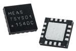
- 型号: TSYS01
- 制造商: MEASUREMENT SPECIALTIES
- 库位|库存: xxxx|xxxx
- 要求:
| 数量阶梯 | 香港交货 | 国内含税 |
| +xxxx | $xxxx | ¥xxxx |
查看当月历史价格
查看今年历史价格
TSYS01产品简介:
ICGOO电子元器件商城为您提供TSYS01由MEASUREMENT SPECIALTIES设计生产,在icgoo商城现货销售,并且可以通过原厂、代理商等渠道进行代购。 提供TSYS01价格参考¥123.02-¥147.63以及MEASUREMENT SPECIALTIESTSYS01封装/规格参数等产品信息。 你可以下载TSYS01参考资料、Datasheet数据手册功能说明书, 资料中有TSYS01详细功能的应用电路图电压和使用方法及教程。
| 参数 | 数值 |
| 产品目录 | |
| 描述 | IC TEMP SENSOR DGTL SMBUS 16QFN板上安装温度传感器 16/24bit Resolution SPI / I2C Interface |
| 产品分类 | 温度传感器,变送器温度传感器 |
| 品牌 | Measurement Specialties Inc. |
| 产品手册 | |
| 产品图片 |
|
| rohs | 符合RoHS无铅 / 符合限制有害物质指令(RoHS)规范要求 |
| 产品系列 | 板上安装温度传感器,Measurement Specialties, Inc. TSYS01- |
| 数据手册 | |
| 产品型号 | G-NICO-018 |
| 产品培训模块 | http://www.digikey.cn/PTM/IndividualPTM.page?site=cn&lang=zhs&ptm=26233 |
| 产品种类 | 板上安装温度传感器 |
| 供应商器件封装 | 16-QFN(4x4) |
| 其它名称 | 223-1134 |
| 准确性 | +/- 0.1 C |
| 包装 | 管件 |
| 商标 | Measurement Specialties, Inc. |
| 安装风格 | SMD/SMT |
| 封装/外壳 | 16-VQFN 裸露焊盘 |
| 封装/箱体 | QFN-16 |
| 感应温度 | -5°C ~ 50°C |
| 最大工作温度 | + 125 C |
| 最小工作温度 | - 40 C |
| 标准包装 | 90 |
| 特色产品 | http://www.digikey.com/product-highlights/cn/zh/measurement-specialties-tsys01-sensors/2982 |
| 电压-电源 | 2.2 V ~ 3.6 V |
| 电源电压-最大 | 3.6 V |
| 电源电压-最小 | 2.2 V |
| 电源电流 | 12.5 uA |
| 精度 | ±0.1°C |
| 设备功能 | Digital Temperature Sensor |
| 输出类型 | 数字 |
| 零件号别名 | G-NICO-018 |


- 商务部:美国ITC正式对集成电路等产品启动337调查
- 曝三星4nm工艺存在良率问题 高通将骁龙8 Gen1或转产台积电
- 太阳诱电将投资9.5亿元在常州建新厂生产MLCC 预计2023年完工
- 英特尔发布欧洲新工厂建设计划 深化IDM 2.0 战略
- 台积电先进制程称霸业界 有大客户加持明年业绩稳了
- 达到5530亿美元!SIA预计今年全球半导体销售额将创下新高
- 英特尔拟将自动驾驶子公司Mobileye上市 估值或超500亿美元
- 三星加码芯片和SET,合并消费电子和移动部门,撤换高东真等 CEO
- 三星电子宣布重大人事变动 还合并消费电子和移动部门
- 海关总署:前11个月进口集成电路产品价值2.52万亿元 增长14.8%


PDF Datasheet 数据手册内容提取
ADC1 S2PI 3I2C Q4FN TSYS01-FAMILY Digital Temperature Sensors SPECIFICATIONS High Accuracy Temperature Sensor TSYS01: ±0.1°C @ Temp.: -5°C … +50°C TSYS01-1: ±0.1°C @ Temp.: -20°C … +70°C 16/24 bit ADC1 Resolution Low Power SPI2/I2C3 Interface QFN416 Package The TSYS01 is a single device Temperature Sensing System (TSYS). The TSYS01 provides factory calibrated temperature information. It includes a temperature sensing chip and a 24-bit ΔΣ-ADC. The essence of the digital 24-bit temperature value and the internal calibration values lead to highly accurate temperature information accompanied by high measurement resolution. The TSYS01 can be interfaced to any microcontroller by an I2C or SPI interface. This microcontroller has to calculate the temperature result based on the ADC values and the calibration parameters. The basic operating principle is: Converting temperature into digital 16/24 bit ADC value Providing calibration coefficients Providing ADC value and calibration coefficients by SPI or I2C interface. 1 Analog tot Digital Conversion 2 Serial Peripheral Interface 3 Inter-Integrated Circuit 4 Quad Flat No-leads SENSOR SOLUTIONS ///TSYS01-FAMILY 09/2017 Page 1
TSYS01-FAMILY Digital Temperature Sensor FEATURES High Accuracy TSYS01: ±0.1°C @ Temp.: -5°C … +50°C TSYS01-1: ±0.1°C @ Temp.: -20°C … +70°C Adjustment of high accuracy temp. range on request Low Current, <12.5 μA (standby < 0.14 μA) SPI / I2C Interface Small Package: QFN16 Operating Temperature Range: -40°C … +125°C APPLICATIONS Industrial Control Replacement of Thermistors and NTCs Heating / Cooling Systems HVAC ABSOLUTE MAXIMUM RATINGS Absolute maximum ratings are limiting values of permitted operation and should never be exceeded under the worst possible conditions either initially or consequently. If exceeded by even the smallest amount, instantaneous catastrophic failure can occur. And even if the device continues to operate satisfactorily, its life may be considerably shortened. Parameter Symbol Conditions Min Typ Max Unit Supply Voltage VDD --- -0.3 --- +3.6 V Operating Temperature Top --- -40 --- +125 °C Storage temperature Tstor --- -55 --- +150 °C Human Body Model (HBM) ESD rating ESD -4 --- +4 kV pin to pin incl. VDD & GND Humidity Hum --- Non condensing --- OPERATING CONDITIONS Parameter Symbol Conditions Min Typ Max Unit Operating Supply Voltage VDD Stabilized 2.2 --- 3.6 V High Accuracy Supply Voltage VDD To achieve Acc1 3.2 --- 3.4 V Supply Current IDD 1 sample per second --- --- 12.5 µA No conversion, VDD = 3V Standby current IS T = 25°C --- 0.02 0.14 µA T = 85°C 0.70 1.40 µA Peak Supply Current IDD During conversion --- 1.4 --- mA Conversion time TCONV 7.40 8.22 9.04 ms Serial Data Clock SPI FSCLK --- --- 20 MHz Serial Data Clock I2C FSCL --- --- 400 kHz VDD Capacitor --- Place close to the chip --- 100nF --- --- SENSOR SOLUTIONS /// TSYS01-FAMILY 09/2017 Page 2
TSYS01-FAMILY Digital Temperature Sensor OPERATIONAL CHARACTERISTICS If not otherwise noted, 3.3V supply voltage is applied. Parameter Symbol Conditions Min Typ Max Unit Temp. Measurement Range TRANG --- -40 --- +125 °C -5°C < T < +50°C TSYS01 VDD = 3.2V – 3.4V Accuracy 1 TACC1 -0.1 --- +0.1 °C -20°C < T < +70°C TSYS01-1 VDD = 3.2V – 3.4V -40°C < T < +125°C Accuracy 2 TACC2 VDD = 3.2V – 3.4V -0.5 --- +0.5 °C Power Supply Reject Ratio PSRR VDD = 2.7 – 3.6 --- --- 0.2 °C T = 25°C, C = 100nF Temperature Resolution TRES --- --- --- 0.01 °C t63 (t1 t2) Tliquid t1t =2 =2 57°5C°C (a (ilriq 0umid/)s ) --- 3 --- s PCB 900mm2 x 1.5mm FR4 Time Constant t63 (t1 t2) Tair t2 = 7t15 =°C 2 5(a°iCr s(tareira 0mm 6/s0) m/s) --- 4 --- s PCB 900mm2 x 1.5mm FR4 Self Heating SH1 10 samples/s, 60s, still air --- --- 0.02 °C ANALOGUE TO DIGITAL CONVERTER Parameter Symbol Conditions Min Typ Max Unit Output Word --- --- 24 bit Conversion Time tc --- 7.40 8.22 9.04 ms DIGITAL INPUTS (SCLK, SDI, CSB, PS) Parameter Symbol Conditions Min Typ Max Unit Input High Voltage VIH VDD = 2.2…3.6V 0.7•VDD --- VDD V Input Low Voltage VIL VDD = 2.2…3.6V 0.0•VDD --- 0.3•VDD V CS5 low to first SCLK6 rising tCSL --- 21 --- --- ns CS high to first SCLK rising tCSH --- 21 --- --- ns SDI7 setup to first SCLK rising TDSO --- 6 --- --- ns SDI hold to first SCLK rising TDO --- 6 --- --- ns DIGITAL OUTPUTS (SDA, SDO) Parameter Symbol Conditions Min Typ Max Unit Output High Voltage VOH ISource = 1mA 0.8•VDD --- VDD V Output Low Voltage VOL ISink = 1mA 0.0•VDD --- 0.2•VDD V SDO8 setup to first SCLK rising tQS --- 10 --- --- ns SDO hold to first SCLK rising tQH --- 0 --- --- ns 5 Chip Select 6 Serial Clock 7 Serial Data Input 8 Serial Data Output SENSOR SOLUTIONS /// TSYS01-FAMILY 09/2017 Page 3
TSYS01-FAMILY Digital Temperature Sensor CONNECTION DIAGRAM PIN FUNCTION TABLE Pin Name Type Function 1 VSS G Ground SPI: Chip Select (active low) 2 CSB DI I2C: Address Selection SPI: Serial Data Clock 3 SCLK/SCL9 DI I2C: Serial Data Clock SPI: Serial Data Input 4 SDI/SDA10 DIO I2C: Data Input / Output 5 SDO DO SPI: Serial Data Output 6 – 14 NC --- Not connected / Do not connect 15 VDD P Supply Voltage 16 PS DI Communication protocol select (0=SPI, 1=I2C) --- DAP --- Die Attach Pad, suggested to connect to VSS 9 Serial Clock Line 10 Serial Data Line SENSOR SOLUTIONS /// TSYS01-FAMILY 09/2017 Page 4
TSYS01-FAMILY Digital Temperature Sensor INTERFACE DESCRIPTION PROTOCOL SELECTION PS pin input level has to be defined in dependence to protocol selection. PS = 0 activates SPI. PS = 1 activates I2C. I2C INTERFACE A I2C communication message starts with a start condition and it is ended by a stop condition. Each command consists of two bytes: the address byte and command byte. I2C ADDRESS SELECTION The I2C address can be selected by CSB pin. CSB=1 the address is 1110110x. CSB=0 the address is 1110111x. Therefore, two TSYS01 can be interfaced on the same I2C bus. SPI INTERFACE The serial interface is a 4-wire SPI bus, operating as a slave. CS (chip select), SCLK (serial clock), SDI (serial data in), and SDO (serial data out) are used to interact with the SPI master. Communication with the chip starts when CS is pulled to low and ends when CS is pulled to high. SCLK is controlled by the SPI master and idles low (SCLK low on CS transitions, mode 0). A mode where the clock alternatively idles high is also supported (mode 3). COMMANDS The commands are the same for SPI and I2C interface. There are four commands: Reset Read PROM (calibration parameters) Start ADC Temperature conversion Read ADC Temperature result Command Hex Value Reset 0x1E Start ADC Temperature Conversion 0x48 Read ADC Temperature Result 0x00 PROM Read Address 0 0xA0 PROM Read Address 1 (Coefficient k4) 0xA2 PROM Read Address 2 (Coefficient k3) 0xA4 PROM Read Address 3 (Coefficient k2) 0xA6 PROM Read Address 4 (Coefficient k1) 0xA8 PROM Read Address 5 (Coefficient k0) 0xAA PROM Read Address 6 (SN23...8) 0xAC PROM Read Address 7 (SN7...0 and Checksum) 0xAE SENSOR SOLUTIONS /// TSYS01-FAMILY 09/2017 Page 5
TSYS01-FAMILY Digital Temperature Sensor RESET SEQUENCE The Reset sequence has to be sent once after power-on. It also can be used to reset the device ROM from an unknown condition. SPI I2C PROM READ SEQUENCE The PROM Read command consists of two parts. First command sets up the system into PROM read mode. The second part gets the data from the system. Below examples are sequences to read address 3 (command 0xA6). SPI I2C SENSOR SOLUTIONS /// TSYS01-FAMILY 09/2017 Page 6
TSYS01-FAMILY Digital Temperature Sensor CONVERSION SEQUENCE A conversion has to be started by sending this command. The sensor stays busy until conversion is done. When conversion is finished the data can be accessed by using ADC read command SPI The last clock will start the conversion which TSYS01 indicates by pulling SDO low. SDO goes high when conversion is completed. I2C When the command is sent the TSYS01 stays busy until the conversion is done. All other commands except the reset command will not be executed during this time. When the conversion is finished the data can be accessed by sending a ADC read command, when an acknowledge appears from TSYS01. READ ADC RESULT After the conversion command the ADC result is read using ADC read command. Repeated ADC read commands, or command executed without prior conversion will return all 0 as result. SPI SENSOR SOLUTIONS /// TSYS01-FAMILY 09/2017 Page 7
TSYS01-FAMILY Digital Temperature Sensor I2C TEMPERATURE CALCULATION CALIBRATION PARAMETER Variable Description Command Size / bit Min Max Example k4 Coefficient k4 of polynomial 0xA2 16 0 65535 28446 k3 Coefficient k3 of polynomial 0xA4 16 0 65535 24926 k2 Coefficient k2 of polynomial 0xA6 16 0 65535 36016 k1 Coefficient k1 of polynomial 0xA8 16 0 65535 32791 k0 Coefficient k0 of polynomial 0xAA 16 0 65535 40781 SENSOR SOLUTIONS /// TSYS01-FAMILY 09/2017 Page 8
TSYS01-FAMILY Digital Temperature Sensor TEMPERATURE POLYNOMAL ADC24: ADC value ADC16: ADC24 / 256 T / °C = (-2) * k * 10-21 * ADC164 + 4 4 * k * 10-16 * ADC163 + 3 (-2) * k * 10-11 * ADC162 + 2 1 * k * 10-6 * ADC16 + 1 (-1.5) * k * 10-2 0 EXAMPLE ADC24: 9378708 ADC16: 9378708 / 256 = 36636 T / °C = (-2) * 28446 * 10-21 * 366364 + 4 * 24926 * 10-16 * 366363 + (-2) * 36016 * 10-11 * 366362 + 1 * 32791 * 10-6 * 36636 + (-1.5) * 40781 * 10-2 T / °C = 10.59 Serial number Content / Description Command Size / bit Example Bit 16 … 8 Bit 7 … 0 SN23...8 0xAC 16 0x0005 (H0 = 0x00, L0 = 0x05) SN7...0 Checksum 0xAE 16 0x96D9 (H0 = 0x96, L0 = 0xD9) Serial number = 28 x SN + SN 23...8 7...0 EXAMPLE Serial number: 28 x 5+ 150 = 1430 Checksum In order to check communication and integrity of PROM content, the PROM includes a checksum. By summarization of the complete PROM content in a byte by byte way, the verification can be performed. The lower byte of the sum result has to be 0x00. SENSOR SOLUTIONS /// TSYS01-FAMILY 09/2017 Page 9
TSYS01-FAMILY Digital Temperature Sensor DIMENSIONS TOP VIEW All dimensions shown in mm SIDE VIEW BOTTOM VIEW Die Attach Pad, suggested to connect to VSS MARKING Line Description Example 1 Manufacturer MEAS 2 Product Name TSYS01 3 Pin 1 Dot, Date Code YYWW 1141 SENSOR SOLUTIONS /// TSYS01-FAMILY 09/2017 Page 10
TSYS01-FAMILY Digital Temperature Sensor ORDER INFORMATION Please order this product using following: Part Number Part Description G-NICO-018 TSYS01 Digital Temperature Sensor G-NICO-023 TSYS01-1 Digital Temperature Sensor EMC Due to the use of these modules for OEM application no CE declaration is done. Especially line coupled disturbances like surge, burst, HF etc. cannot be removed by the module due to the small board area and low price feature. There is no protection circuit against reverse polarity or over voltage implemented. NORTH AMERICA EUROPE ASIA Measurement Specialties, Inc. Measurement Specialties (Europe), Ltd., Measurement Specialties (China), Ltd., a TE Connectivity Company A TE Connectivity Company a TE Connectivity Company Tel 800-522-6752 Tel 800-440-5100 Tel 0400-820-6049 customercare.hmpt@te.com customercare.dtmd@te.com customercare.shzn@te.com TE.com/sensorsolutions Measurement Specialties, Inc., a TE Connectivity company. TE Connectivity, TE connectivity (logo) are trademarks. All other logos, products and/or company names referred to herein might be trademarks of their respective owners. The information given herein, including drawings, illustrations and schematics which are intended for illustration purposes only, is believed to be reliable. However, TE Connectivity makes no warranties as to its accuracy or completeness and disclaims any liability in connection with its use. TE Connectivity‘s obligations shall only be as set forth in TE Connectivity‘s Standard Terms and Conditions of Sale for this product and in no case will TE Connectivity be liable for any incidental, indirect or consequential damages arising out of the sale, resale, use or misuse of the product. Users of TE Connectivity products should make their own evaluation to determine the suitability of each such product for the specific application. © 2017 TE Connectivity Ltd. family of companies All Rights Reserved. SENSOR SOLUTIONS /// TSYS01-FAMILY 09/2017 Page 11
Mouser Electronics Authorized Distributor Click to View Pricing, Inventory, Delivery & Lifecycle Information: T E Connectivity: TSYS01