ICGOO在线商城 > TSP6D138M010AH6510D540
 Datasheet下载
- 型号: TSP6D138M010AH6510D540
- 制造商: Kemet
- 库位|库存: xxxx|xxxx
- 要求:
| 数量阶梯 | 香港交货 | 国内含税 |
| +xxxx | $xxxx | ¥xxxx |
查看当月历史价格
查看今年历史价格
TSP6D138M010AH6510D540产品简介:
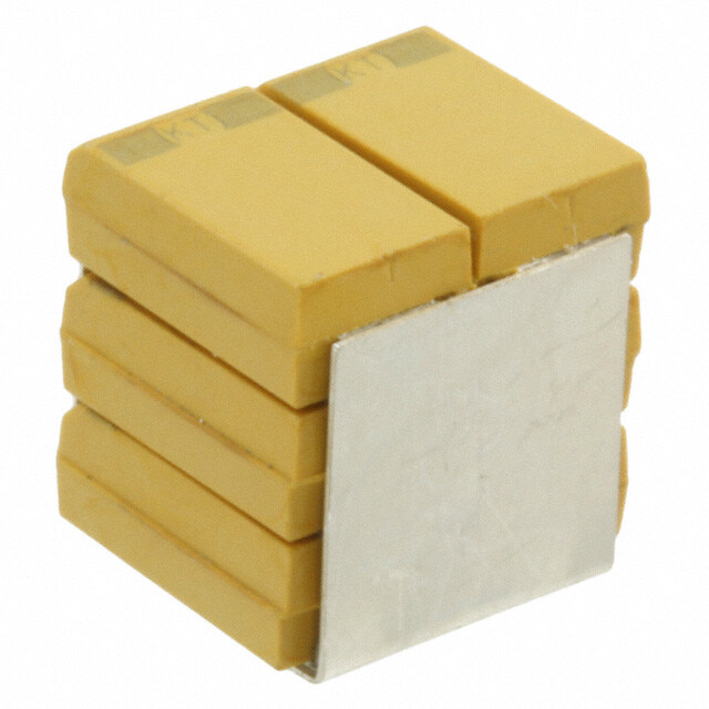
ICGOO电子元器件商城为您提供TSP6D138M010AH6510D540由Kemet设计生产,在icgoo商城现货销售,并且可以通过原厂、代理商等渠道进行代购。 提供TSP6D138M010AH6510D540价格参考以及KemetTSP6D138M010AH6510D540封装/规格参数等产品信息。 你可以下载TSP6D138M010AH6510D540参考资料、Datasheet数据手册功能说明书, 资料中有TSP6D138M010AH6510D540详细功能的应用电路图电压和使用方法及教程。
KEMET TSP6D138M010AH6510D540 是一款高性能表面贴装钽电容器,其标称容量为1300 µF(138即13×10⁸ pF = 1300 µF),额定电压10 V,容差±20%(M),符合AEC-Q200汽车级可靠性标准(后缀H表示符合汽车应用要求),封装为6D(尺寸约7.3×4.3×2.8 mm),低ESR(典型值约54 mΩ),采用导电聚合物阴极技术。

该器件主要应用于对可靠性、纹波电流耐受性及长期稳定性要求严苛的汽车电子系统,如:车载信息娱乐主机(IVI)的电源滤波;高级驾驶辅助系统(ADAS)中摄像头模组、雷达模块的供电去耦;车身控制模块(BCM)和网关控制器的DC-DC转换器输出端滤波;以及新能源车中BMS(电池管理系统)的信号调理与稳压电路。其高容值、小体积和低ESR特性,特别适合在空间受限且需抑制高频噪声的12 V/5 V/3.3 V多路电源轨中替代电解电容,提升系统能效与寿命。此外,亦可用于工业自动化PLC电源、医疗便携设备等高可靠性领域。不适用于高浪涌电流或反向电压场景,须严格遵守降额设计(建议电压降额至≤50%,即工作电压≤5 V)。
| 参数 | 数值 |
| 产品目录 | |
| 描述 | CAP TANT 1320UF 10V 20% SMD钽质电容器-SMD聚合物 10volts 1320uF 20% |
| ESR | 4.2 mOhms |
| ESR(等效串联电阻) | 4.2 毫欧 |
| 产品分类 | |
| 品牌 | Kemet |
| 产品手册 | |
| 产品图片 |
|
| rohs | 否含铅 / 不符合限制有害物质指令(RoHS)规范要求 |
| 产品系列 | 高分子电容器,钽质电容器-SMD聚合物,Kemet TSP6D138M010AH6510D540TSP |
| 数据手册 | |
| 产品型号 | TSP6D138M010AH6510D540 |
| 不同温度时的使用寿命 | - |
| 产品 | Tantalum Organic Polymer Standard Grade |
| 产品培训模块 | http://www.digikey.cn/PTM/IndividualPTM.page?site=cn&lang=zhs&ptm=25569 |
| 产品种类 | 钽质电容器-SMD聚合物 |
| 其它名称 | 399-6212 |
| 制造商尺寸代码 | 6D |
| 制造商库存号 | 6D Case |
| 包装 | 托盘 |
| 商标 | Kemet |
| 外壳代码-in | 3135 |
| 外壳代码-mm | 8089 |
| 外壳宽度 | 8.9 mm |
| 外壳长度 | 8 mm |
| 大小/尺寸 | 0.315" 长 x 0.350" 宽(8.00mm x 8.90mm) |
| 安装类型 | 表面贴装 |
| 容差 | 20 % |
| 封装 | Bulk |
| 封装/外壳 | 堆叠式 SMD,3 条 J 形引线 |
| 封装/箱体 | 3135 (8089 metric) |
| 工作温度 | -55°C ~ 125°C |
| 工作温度范围 | - 55 C to + 125 C |
| 工厂包装数量 | 50 |
| 引线间距 | - |
| 损耗因数DF | 10 |
| 标准包装 | 25 |
| 漏泄电流 | 1320 uA |
| 特性 | COTS(高可靠性) |
| 电压-额定 | 10V |
| 电压额定值 | 10 V |
| 电容 | 1320 uF |
| 端接类型 | SMD/SMT |
| 类型 | 模制 |
| 系列 | TSP |
| 高度 | 9.2 mm |
| 高度-安装(最大值) | 0.377"(9.58mm) |


- 商务部:美国ITC正式对集成电路等产品启动337调查
- 曝三星4nm工艺存在良率问题 高通将骁龙8 Gen1或转产台积电
- 太阳诱电将投资9.5亿元在常州建新厂生产MLCC 预计2023年完工
- 英特尔发布欧洲新工厂建设计划 深化IDM 2.0 战略
- 台积电先进制程称霸业界 有大客户加持明年业绩稳了
- 达到5530亿美元!SIA预计今年全球半导体销售额将创下新高
- 英特尔拟将自动驾驶子公司Mobileye上市 估值或超500亿美元
- 三星加码芯片和SET,合并消费电子和移动部门,撤换高东真等 CEO
- 三星电子宣布重大人事变动 还合并消费电子和移动部门
- 海关总署:前11个月进口集成电路产品价值2.52万亿元 增长14.8%

(SN).jpg)


PDF Datasheet 数据手册内容提取
KEMET Organic Capacitor (KO-CAP®) – Industrial Tantalum Stack Polymer (TSP) Electrolytic Stack, 3 – 63 VDC Overview The KEMET Tantalum Stack Polymer (TSP) Electrolytic The TSP series is the first polymer electrolytic capacitor Capacitor is designed to provide the highest CV available with failure rate options when utilizing KEMET's (capacitance/voltage) ratings in a surface mount T540 and T541 Series. The failure rate is determined by configuration. All of KEMET's Polymer Electrolytic Solutions utilizing accelerated conditions (voltage and temperature) are available in a stack configuration.The only exceptions applied to board mounted samples to assess long term are the facedown series (T523,T527,T528, and T529). device reliability. The failure rates available are B (0.1% per These capacitors are utilized in stacks of 2,3,4, and 6 1,000 hours), C (0.01% per 1,000 hours), and D (0.001% per components to achieve a broad range of capacitance, 1,000 hours). This method was developed based on over ten ESR, and voltage ratings. The TSP series may be operated (10) years of research and is described in numerous papers at steady state voltages up to 90% of rated voltage for available on www.kemet.com. part types with rated voltage less than or equal to 10 volts and up to 80% of rated voltage for part types greater Note: Custom stacking solutions are also available with other KEMET than 10 volts. Stacking configurations allow for custom Polymer Electrolytic Surface Mount products. Please contact KEMET Sales for availability. capacitance/voltage solutions and very low ESR options. Benefits • Polymer cathode technology • High capacitance • Surface mountable • Capacitance values of 20 – 6,000 µF • Capacitance can be custom specified • Voltage ratings of 3 – 63 VDC • High volumetric efficiency • Ultra low ESR • Surge capability • Operating temperature range of −55˚C to +125˚C • Laser-marked case • Use up to 90% of rated voltage for part types ≤ 10 V • Use up to 80% of rated voltage for part types > 10 V • KEMET's PERA method testing Applications Typical applications include decoupling and filtering in a variety of market segments. The T540 Polymer COTS stack devices can be utilized in defense and aerospace applications. Other KEMET series can be utilized in filtering and decoupling applications to service various market segments. Environmental Compliance RoHS Compliant (6/6) according to Directive 2002/95/EC when ordered with 100% Sn solder. One world. One KEMET © KEMET Electronics Corporation • KEMET Tower • One East Broward Boulevard T2029_TSP • 9/25/2019 1 Fort Lauderdale, FL 33301 USA • 954-766-2800 • www.kemet.com
KEMET Organic Capacitor (KO-CAP®) – Industrial Tantalum Stack Polymer (TSP) Electrolytic Stack, 3 – 63 VDC K-SIM For a detailed analysis of specific part numbers, please visit ksim.kemet.com to access KEMET's K-SIM software. KEMET K-SIM is designed to simulate behavior of components with respect to frequency, ambient temperature, and DC bias levels. Ordering Information T540/T541 Discrete Component T SP 2D 207 M 010 A H 65 20 D 540 Rated Failure Termination Termination Discrete Capacitor Case Capacitance Capacitance Surge ESR Series Voltage Rate Finish Finish Components Class Size Code (pF) Tolerance (Discrete) (Stack) (VDC) (Discrete) (Discrete) (Stack) Series T = Stacks 2B First two digits K = ±10% 003 = 3 A = N/A H = Standard 65 = 4 cycles at 25°C ±5°C 05 = ESR - High D = Silver-plated 540 = T540 Tantalum Polymer 3B represent M = ±20% 004 = 4 B = 0.1%/ solder 66 = 10 cycles at 25°C 10 = ESR - Standard (Ag) 541 = T541 Cathode 4B significant 006 = 6.3 KHrs coated 67 = 10 cycles at −55°C 20 = ESR-Low H = Solder-plated 6B figures. Third 010 = 10 C = 0.01%/ (SnPb 5% Pb +0°C/−5°C and 85°C (SnPb 5% Pb 2C digit specifies 016 = 16 KHrs minimum) minimum) 3C number of 025 = 25 D = 0.001%/ 85 = 4 cycles at 25°C ±5°C T = 100% Tin (Sn) 4C zeros. 035 = 35 KHrs T = 100% and improved humidity 6C 050 = 50 Matte Tin capability 2D 063 = 63 (Sn)-plated 86 = 10 cycles at 25°C ±5°C 3D and improved humidity 4D capability 6D 87 = 10 cycles at −55°C 2O +0°C/−5°C and +85°C ±5°C 3O and improved humidity 40 capability 6O 2X *** E = None 3X ** S = 10 cycles at 25°C 4X ** W = 10 cycles at −55°C 6X and 85°C T543 Discrete Component T SP 6X 207 M 050 A H E 040 D 543 Rated Failure Termination Termination Discrete Capacitor Case Capacitance Capacitance Surge ESR Series Voltage Rate Finish Finish Components Class Size Code (pF) Tolerance (Discrete) (Stack) (VDC) (Discrete) (Discrete) (Stack) Series T = Stacks 2B First two digits K = ±10% 003 = 3 A = N/A H = Standard E = None ESR in mΩ D = Silver-plated 543 = T543 Tantalum Polymer 3B represent M = ±20% 004 = 4 solder S = 10 cycles at 25°C (Ag) Cathode 4B significant 006 = 6.3 coated W = 10 cycles −55°C and H = Solder-plated 6B figures. Third 010 = 10 (SnPb 5% Pb 85°C (SnPb 5% Pb 2C digit specifies 016 = 16 minimum) minimum) 3C number of 025 = 25 T = 100% Tin (Sn) 4C zeros. 035 = 35 T = 100% 6C 050 = 50 Matte Tin 2D 063 = 63 (Sn)-plated 3D 4D 6D 2O 3O 4O 6O 2X 3X 4X 6X © KEMET Electronics Corporation • KEMET Tower • One East Broward Boulevard T2029_TSP • 9/25/2019 22 Fort Lauderdale, FL 33301 USA • 954-766-2800 • www.kemet.com
KEMET Organic Capacitor (KO-CAP®) – Industrial Tantalum Stack Polymer (TSP) Electrolytic Stack, 3 – 63 VDC Ordering Information cont. T520, T521, T525, T530, T545 Discrete Component T SP 2X 667 M 10 A T E 002 D 530 Rated Failure Termination Termination Discrete Capacitor Case Capacitance Capacitance Surge ESR Series Voltage Rate Finish Finish Components Class Size Code (pF) Tolerance (Discrete) (Stack) (VDC) (Discrete) (Discrete) (Stack) Series T = Stacks 2B First two digits K = ±10% 003 = 3 A = N/A H = Standard E = None ESR in mΩ D = Silver-plated (Ag) 520 = T520 Tantalum Polymer 3B represent M = ±20% 004 = 4 solder coated H = Solder-plated 521 = T521 Cathode 4B significant 006 = 6.3 (SnPb 5% Pb (SnPb 5% Pb minimum) 525 = T525 6B figures. Third 010 = 10 minimum) T = 100% Tin (Sn) 530 = T530 2C digit specifies 016 = 16 545 = T545 3C number of 025 = 25 T = 100% 4C zeros. 035 = 35 Matte Tin 6C 050 = 50 (Sn)-plated 2D 063 = 63 3D 4D 6D 2O 3O 4O 6O 2X 3X 4X 6X Note: Custom discrete component stacking solutions are also available with other KEMET Polymer Electrolytic Surface Mount series/products. Please contact KEMET Sales for availability. Performance Characteristics Item Performance Characteristics Operating Temperature −55°C to 125°C Rated Capacitance Range 20 – 6,000 μF at 120 Hz/25°C Capacitance Tolerance M Tolerance (20%) Rated Voltage Range 3 – 63 V DF (120 Hz) Refer to Part Number Electrical Specification Table ESR (100 kHz) Refer to Part Number Electrical Specification Table Leakage Current ≤ 0.1 CV (µA) at rated voltage after 5 minutes © KEMET Electronics Corporation • KEMET Tower • One East Broward Boulevard T2029_TSP • 9/25/2019 33 Fort Lauderdale, FL 33301 USA • 954-766-2800 • www.kemet.com
KEMET Organic Capacitor (KO-CAP®) – Industrial Tantalum Stack Polymer (TSP) Electrolytic Stack, 3 – 63 VDC Qualification Test Condition Characteristics Δ C/C Within −20/+10% of initial value 105°C at rated voltage, 2,000 hours DF ≤ initial limit Endurance 125°C at 2/3 rated voltage, 2,000 hours DCL 1.25 x IL at 125°C ESR 2 x initial limit Δ C/C Within ±5% of initial value KEMET specified test, mounted, −55°C to 125°C, DF Within initial limits Thermal Shock 5 cycles DCL Within 1.25 x initial limit ESR Within initial limits Δ C/C Within ±5% of initial value DF Within initial limits Surge Voltage 85°C, 1.15 x rated voltage 1,000 cycles DCL Within initial limits ESR Within initial limits Δ C/C Within ±5% of initial value DF Within initial limits Surge Voltage 125°C, 0.77 x rated voltage 1,000 cycles DCL Within initial limits ESR Within initial limits Δ C/C Within ±10 of initial value MIL–STD–202, Method 204, Condition D, Mechanical Vibration DF Within initial limits 10 Hz to 2,000 Hz, 20 G peak DCL Within initial limits © KEMET Electronics Corporation • KEMET Tower • One East Broward Boulevard T2029_TSP • 9/25/2019 44 Fort Lauderdale, FL 33301 USA • 954-766-2800 • www.kemet.com
KEMET Organic Capacitor (KO-CAP®) – Industrial Tantalum Stack Polymer (TSP) Electrolytic Stack, 3 – 63 VDC Reliability KO-CAP capacitors have an average failure rate of 0.5 %/1,000 hours at category voltage, U , and category temperature, T . C C These capacitors are qualified using industry test standards at U and T . The minimum test time (1,000 or 2,000 hours) is C C dependent on the product. The actual life expectancy of KO-CAP capacitors increases when application voltage, U , and application temperature, T , are A A lower than U and T . As a general guideline, when U < 0.9 * U and T < 85°C, the life expectancy will typically exceed the C C A C A useful lifetime of most hardware (> 10 years). The lifetime of a KO-CAP capacitor at a specific application voltage and temperature can be modeled using the equations below. A failure is defined as passing enough current to blow a 1-Amp fuse. The calculation is an estimation based on empirical results and is not a guarantee. (U )n [E ( 1 1 )] VAF = C a U TAF = e k 273+T 273+T A A C where: where: TAF = acceleration factor due to temperature, unitless VAF = acceleration factor due to voltage, unitless E = activation energy, 1.4 eV U = category voltage, volt a C k = Boltzmann’s constant, 8.617E-5 eV/K U = application voltage, volt T = application temperature, °C A A n = exponent, 16 T = category temperature, °C C AF = VAF * TAF Life = Life * AF U ,T U ,T A A C C where: where: Life = guaranteed life application voltage UA, TA AF = acceleration factor, unitless and temperature, years TAF = accerlation factor due to temperature, unitless Life = guaranteed life category voltage UC, TC and temperature, years VAF = acceleration factor due to voltage, unitless AF = acceleration factor, unitless Reliability Table 1 – Common temperature range classifications 85°C (TR) / Rated Voltage (UR) 2.5 4.0 6.3 8.0 10.0 12.5 16.0 20.0 25.0 35.0 50.0 63.0 75.0 85°C (TC) Category Voltage (UC) 2.5 4.0 6.3 8.0 10.0 12.5 16.0 20.0 25.0 35.0 50.0 63.0 75.0 105°C (TR) / Rated Voltage (UR) 2.5 4.0 6.3 8.0 10.0 12.5 16.0 20.0 25.0 35.0 50.0 63.0 75.0 105°C (TC) Category Voltage (UC) 2.5 4.0 6.3 8.0 10.0 12.5 16.0 20.0 25.0 35.0 50.0 63.0 75.0 105°C (TR) / Rated Voltage (UR) 2.5 4.0 6.3 8.0 10.0 12.5 16.0 20.0 25.0 35.0 50.0 63.0 75.0 125°C (TC) Category Voltage (UC) 1.7 2.7 4.2 5.4 6.7 8.4 10.7 13.4 16.8 23.5 33.5 42.2 50.3 Terms: Category Voltage, U : Maximum recommended peak DC operating voltage for continuous operation at the category temperature, T C C Rated Voltage, U : Maximum recommended peak DC operating voltage for continuous operation up to the rated temperature, T R R Category Temperature, T : Maximum recommended operating temperature; voltage derating may be required at T C C Rated Temperature, T : Maximum recommended operating temperature without voltage derating; T is equal to or lower than T R R C © KEMET Electronics Corporation • KEMET Tower • One East Broward Boulevard T2029_TSP • 9/25/2019 55 Fort Lauderdale, FL 33301 USA • 954-766-2800 • www.kemet.com
KEMET Organic Capacitor (KO-CAP®) – Industrial Tantalum Stack Polymer (TSP) Electrolytic Stack, 3 – 63 VDC Dimensions – Millimeters (Inches) TSM2 TSM4 Metric will govern TSP2 TSP4 SIDE VIEW ANODE (+) END VIEW SIDE VIEW ANODE (+) END VIEW TSM2 TSM4 TSP2 L W L W TSP2 TSP4 KEMET 2 Component Stack Dimensions SIDE VIEW ANODE (+) END VIEW SIDE VIEW ANODE (+) END VIEW Case L H W L H W Code L W H W2 H2 P H2 H2 6.5 ±0.38 3.3 ±0.2 5.3 ±0.38 2.5 ±0.2 4.5 ±0.38 1.4 ±0.38 2C (0.258 ±0.015) (0.130 ±0.008) (0.210 ±0.015) (0.100 ±0.008) (0.176 ±0.015) (0.055 ±0.015) P H W2 P H W2 2B 4.1 ±0.38 3.1 ±0.2 4.3 ±0.38 2.3 ±0.2 3.1 ±0.38 0.76 ±0.38 H2 H2 (0.162 ±0.015) (0.122 ±0.008) (0.170 ±0.015) (0.090 ±0.008) (0.124 ±0.015) (0.030 ±0.015) 8.0 ±0.38 4.4 ±0.2 6.2 ±0.38 3.0 ±0.2 4.8 ±0.38 1.9 ±0.38 2D (0.315 ±0.015) (0.174 ±0.008) (0.245 ±0.015) (0.120 ±0.008) (0.192 ±0.015) (0.075 ±0.015) P W2 P W2 TSM3 TSM6 8.0 ±0.38 4.4 ±0.2 8.9 ±0.38 3.0 ±0.2 6.9 ±0.38 1.9 ±0.38 2X (0.315 ±0.015) (0.174 ±0.008) (0.352 ±0.015) (0.120 ±0.008) (0.272 ±0.015) (0T.07S5 ±P0.0315) TSP6 SIDE VIEW ANODE (+) END VIEW SIDE VIEW ANODE (+) END VIEW TSM3 TSM6 TSP3 L W L W TSP3 TSP6 KEMET 3 Component Stack Dimensions SIDE VIEW ANODE (+) END VIEW SIDE VIEW ANODE (+) END VIEW Case L W H W H P L W L W Code 2 2 H H 4.1 ±0.38 3.1 ±0.2 6.3 ±0.38 2.3 ±0.2 5.3 ±0.38 0.76 ±0.38 3B (0.162 ±0.015) (0.122 ±0.008) (0.248 ±0.015) (0.090 ±0.008) (0.210 ±0.015) (0.030 ±0.015) H2 H2 8.0 ±0.38 4.4 ±0.2 9.2 ±0.38 3.0 ±0.2 7.7 ±0.38 1.9 ±0.38 3D (0.315 ±0.015) (0.174 ±0.008) (0.365 ±0.015) (0.120 ±0.008) (0.304 ±0.015) (0.075 ±0.015) H H TSM2 8.0 ±0.38 4.4 ±0.2 13.3 ±0.38 3.0 ±0.2 11.0 ±0.38 TS1M.9 ±04.38 H2 H2 3X (0.315 ±0.015) (0.174 ±0.008) (0.525 ±0.015) (0.120 ±0.008) (0.436 ±0.015) (0.075 ±0.015) P W2 P W2 TSP2 TSP4 TSM2 TSM4 SIDE VIEW ANODE (+) END VIEW SIDE VIEW ANODE (+) END VIEW TSP2TSP4 L W TSP4 L W P W2 P W2 SIDE VIEW ANODE (+) END VIEW SIDE VIEW ANODE (+) END VIEW KEMET 4 Component Stack Dimensions L W L W Case H H Code L W H H2 W2 H2 P H2 4.1 ±0.38 6.1 ±0.2 4.3 ±0.38 5.3 ±0.2 3.1 ±0.38 0.76 ±0.38 4B H H (0.162 ±0.015) (0.242 ±0.008) (0.170 ±0.015) (0.210 ±0.008) (0.124 ±0.015) (0.030 ±0.015) P W2 H2 P W2 H2 8.0 ±0.38 8.9 ±0.2 6.2 ±0.38 7.4 ±0.2 4.8 ±0.38 1.9 ±0.38 4D (0.315 ±0.015) (0.350 ±0.008) (0.245 ±0.015) (0.292 ±0.008) (0.192 ±0.015) (0.075 ±0.015) 4X P 8.0 ±0.38 8.9 ±0.2 8.9 ±0 W.32 8 7.4 ±0.2 6.9 ±0.38 1.9 ±0.38 P W2 (0.315 ±0.015) (0.350 ±0.008) (0.352 ±0.015) (0.292 ±0.008) (0.272 ±0.015) (0.075 ±0.015) TSM3 TSM6 TSP3TSP6 TSP6 TSM3 TSM6 SIDE VIEW ANODE (+) END VIEW SIDE VIEW ANODE (+) END VIEW TSP3 L KEMET 6 Componen Wt Stack Dimensions TSP6 L W Case SLIDE VIEW W ANODEH (+) END VIEW W2 H2 P SIDE VIEW ANODE (+) END VIEW Code L W L W 4.1 ±0.38 6.1 ±0.2 6.3 ±0.38 5.3 ±0.2 5.3 ±0.38 0.76 ±0.38 6B (0.162 ±0.015) (0.242 ±0.008) (0.248 ±0.015) (0.210 ±0.008) (0.210 ±0.015) (0.030 ±0.015) H H 8.0 ±0.38 8.9 ±0.2 9.2 ±0.38 7.4 ±0.2 7.7 ±0.38 1.9 ±0.38 6D (0.315 ±0.015) (0.350 ±0.008) (0.365 ±0.015) (0 H.22 92 ±0.008) (0.304 ±0.015) (0.075 ±0.015) H2 6X 8.0 ±0.38 8.9 ±0 H.2 13.3 ±0.38 7.4 ±0.2 11.0 ±0.38 1.9 ±0.38 H (0.315 ±0.015) (0.350 ±0.008) (0.525 ±0.015) (0 H.22 92 ±0.008) (0.436 ±0.015) (0.075 ±0.015) H2 P W2 P W2 © KEMET E Plectronics Corporation • KEMET TWo2 wer • One East Broward Boulevard P T2029_TSP • W9/2 25/2019 66 Fort Lauderdale, FL 33301 USA • 954-766-2800 • www.kemet.com
KEMET Organic Capacitor (KO-CAP®) – Industrial Tantalum Stack Polymer (TSP) Electrolytic Stack, 3 – 63 VDC Capacitance and Rated Voltage Chart Capacitance Rated Voltage µf Code 3V 4V 6.3V 10 16 25 35 50 63 20 206 2X 30 306 2X, 3X 40 406 4X 44 446 2X 45 456 3X 60 606 4X, 6X 66 666 2B 2X 2X, 3X 88 886 4X 90 906 6X 94 946 2D 2X 99 996 3B 100 107 3X 3X 130 137 2B 4B 2X 4X 4X, 6X 140 147 3D 3X 190 197 4D 4X 198 207 6B 200 207 2B 3B 2D 3X 6X 6X 260 267 4X 272 277 4B 280 287 6D 6X 300 307 3B 2D 2X 400 407 4B 6B 4D 6X 440 447 2D 2D 2X 450 457 3B 3X 600 607 4B 6B 4X 660 667 2D 2D 3D, 2X 2X, 3X 880 887 4D 4D 4X 900 907 6B 6D 6X 940 947 2D 2X 990 997 3D 3X 3X 1300 138 2X 4D 6D, 4X 4X, 6X 1360 148 2D 1400 148 3D 3X 1900 198 4D 4X 1980 208 6D 2000 208 3D 2X, 3X 6X 6X 2700 278 4D 4X 2800 288 6D 6X 3000 308 3X 4000 408 6D 4X, 6X 6000 608 6X © KEMET Electronics Corporation • KEMET Tower • One East Broward Boulevard T2029_TSP • 9/25/2019 77 Fort Lauderdale, FL 33301 USA • 954-766-2800 • www.kemet.com
KEMET Organic Capacitor (KO-CAP®) – Industrial Tantalum Stack Polymer (TSP) Electrolytic Stack, 3 – 63 VDC Table 1A – TSP2 Ratings & Part Number Reference Maximum Rated Rated Case Code/ DC Standard KEMET Part Number DF Low ESR Operating Voltage Capacitance Case Size Leakage ESR Temp (See below for µA at +25°C % at +25°C mΩ at +25°C mΩ at +25°C VDC at 105°C µF KEMET/EIA °C part options) Max/5 Min 120 Hz Max 100 kHz Max 100 kHz Max 4 200 2B TSP2B207(4)004(6)(3)(1)(2)(5)540 80 8 40 N/A 125 6.3 130 2B TSP2B137(4)006(6)(3)(1)(2)(5)540 86 8 40 N/A 125 10 66 2B TSP2B666(4)010(6)(3)(1)(2)(5)540 66 8 40 N/A 125 3 660 2D TSP2D667(4)003(6)(3)(1)(2)(5)540 198 10 13 N/A 125 3 1400 2D TSP2D148(4)003(6)(3)(1)(2)(5)540 408 10 13 N/A 125 4 440 2D TSP2D447(4)004(6)(3)(1)(2)(5)540 176 10 13 N/A 125 4 940 2D TSP2D947(4)004(6)(3)(1)(2)(5)540 376 10 20 13 125 6.3 660 2D TSP2D667(4)006(6)(3)(1)(2)(5)540 416 10 20 13 125 10 200 2D TSP2D207(4)010(6)(3)(1)(2)(5)540 200 10 28 13 125 10 300 2D TSP2D307(4)010(6)(3)(1)(2)(5)540 300 10 28 13 125 10 440 2D TSP2D447(4)010(6)(3)(1)(2)(5)540 440 10 13 N/A 125 16 94 2D TSP2D946(4)016(6)(3)(1)(2)(5)540 152 10 33 18 125 4 1300 2X TSP2X138(4)004(6)(3)(1)(2)(5)541 520 10 5 3 125 4 2000 2X TSP2X208(4)004(6)(3)(1)(2)(5)541 800 10 5 3 125 6.3 940 2X TSP2X947(4)006(6)(3)(1)(2)(5)541 564 10 5 3 125 10 660 2X TSP2X667(4)010(6)(3)(1)(2)(5)541 660 10 5 3 125 16 300 2X TSP2X307(4)016(6)(3)(1)(2)(5)541 480 10 20 12 125 16 440 2X TSP2X447(4)016(6)(3)(1)(2)(5)541 704 10 20 12 125 16 660 2X TSP2X667(4)016(6)(3)(1)(2)(5)541 1056 10 25 12 125 25 130 2X TSP2X137(4)025(6)(3)(1)(2)(5)541 325 10 25 N/A 125 35 66 2X TSP2X666(4)035(6)(3)(1)(2)(5)541 231 10 30 N/A 125 35 94 2X TSP2X946(4)035(6)(3)(1)(2)(5)541 329 10 30 N/A 125 50 44 2X TSP2X446(4)050(6)(3)(1)(2)(5)541 220 10 40 N/A 125 50 66 2X TSP2X666(4)050(6)(3)(1)(2)(5)541 330 10 40 N/A 125 63 20 2X TSP2X206(4)063(6)(3)(1)(2)(5)541 126 10 75 50 125 63 30 2X TSP2X306(4)063(6)(3)(1)(2)(5)541 189 10 25 N/A 125 (1) To complete KEMET part number, insert 65 = None, 66 = 10 cycles +25°C, 67 = 10 cycles −55°C +85°C. Designates surge current option. (2) To complete KEMET part number, insert 10 = Standard ESR, 20 = Low ESR. Designates ESR option. (3) To complete KEMET part number, insert H = Standard solder coated or T = 100% Tin (4) To complete KEMET part number, insert M for ±20%, K for ±10%. Designates Capacitance tolerance. (5) To complete KEMET part number, insert D = Silver-plated (Ag) , H = Solder-plated, or T = 100% Tin (Sn). Designates Termination Finish (stack) (6) To complete KEMET part number, insert D (0.001%/1,000 hours), C (0.01%/1,000 hours), B (0.1%/1,000 hours), or A = N/A. Designates Reliability Level. Refer to Ordering Information for additional detail. © KEMET Electronics Corporation • KEMET Tower • One East Broward Boulevard T2029_TSP • 9/25/2019 88 Fort Lauderdale, FL 33301 USA • 954-766-2800 • www.kemet.com
KEMET Organic Capacitor (KO-CAP®) – Industrial Tantalum Stack Polymer (TSP) Electrolytic Stack, 3 – 63 VDC Table 1B – TSP3 Ratings & Part Number Reference Maximum Rated Rated Case Code/ DC Standard KEMET Part Number DF Low ESR Operating Voltage Capacitance Case Size Leakage ESR Temp (See below for µA at +25°C % at +25°C mΩ at +25°C mΩ at +25°C VDC at 105°C µF KEMET/EIA °C part options) Max/5 Min 120 Hz Max 100 kHz Max 100 kHz Max 3 450 3B TSP3B457(4)003(6)(3)(1)(2)(5)540 135 8 27 N/A 125 4 300 3B TSP3B307(4)004(6)(3)(1)(2)(5)540 120 8 27 N/A 125 6.3 200 3B TSP3B207(4)006(6)(3)(1)(2)(5)540 129 8 27 N/A 125 10 99 3B TSP3B996(4)010(6)(3)(1)(2)(5)540 99 8 27 N/A 125 3 2000 3D TSP3D208(4)003(6)(3)(1)(2)(5)540 612 10 9 N/A 125 4 1400 3D TSP3D148(4)004(6)(3)(1)(2)(5)540 564 10 14 9 125 6.3 990 3D TSP3D997(4)006(6)(3)(1)(2)(5)540 624 10 14 9 125 10 660 3D TSP3D667(4)010(6)(3)(1)(2)(5)540 660 10 9 N/A 125 16 140 3D TSP3D147(4)016(6)(3)(1)(2)(5)540 226 10 22 12 125 4 2000 3X TSP3X208(4)004(6)(3)(1)(2)(5)541 800 10 3 2 125 4 3000 3X TSP3X308(4)004(6)(3)(1)(2)(5)541 1200 10 3 2 125 6.3 1400 3X TSP3X148(4)006(6)(3)(1)(2)(5)541 840 10 3 2 125 10 990 3X TSP3X997(4)010(6)(3)(1)(2)(5)541 990 10 3 2 125 16 450 3X TSP3X457(4)016(6)(3)(1)(2)(5)541 720 10 15 9 125 16 660 3X TSP3X667(4)016(6)(3)(1)(2)(5)541 1056 10 15 9 125 16 990 3X TSP3X997(4)016(6)(3)(1)(2)(5)541 1584 10 18 9 125 25 200 3X TSP3X207(4)025(6)(3)(1)(2)(5)541 500 10 18 N/A 125 35 100 3X TSP3X107(4)035(6)(3)(1)(2)(5)541 350 10 20 N/A 125 35 140 3X TSP3X147(4)035(6)(3)(1)(2)(5)541 490 10 20 N/A 125 50 66 3X TSP3X666(4)050(6)(3)(1)(2)(5)541 330 10 25 N/A 125 50 100 3X TSP3X107(4)050(6)(3)(1)(2)(5)541 500 10 25 N/A 125 63 30 3X TSP3X306(4)063(6)(3)(1)(2)(5)541 189 10 50 35 125 63 45 3X TSP3X456(4)063(6)(3)(1)(2)(5)541 283.5 10 18 N/A 125 (1) To complete KEMET part number, insert 65 = None, 66 = 10 cycles +25°C, 67 = 10 cycles −55°C +85°C. Designates surge current option. (2) To complete KEMET part number, insert 10 = Standard ESR, 20 = Low ESR. Designates ESR option. (3) To complete KEMET part number, insert H = Standard solder coated or T = 100% Tin (4) To complete KEMET part number, insert M for ±20%, K for ±10%. Designates Capacitance tolerance. (5) To complete KEMET part number, insert D = Silver-plated (Ag) , H = Solder-plated, or T = 100% Tin (Sn). Designates Termination Finish (stack) (6) To complete KEMET part number, insert D (0.001%/1,000 hours), C (0.01%/1,000 hours), B (0.1%/1,000 hours), or A = N/A. Designates Reliability Level. Refer to Ordering Information for additional detail. © KEMET Electronics Corporation • KEMET Tower • One East Broward Boulevard T2029_TSP • 9/25/2019 99 Fort Lauderdale, FL 33301 USA • 954-766-2800 • www.kemet.com
KEMET Organic Capacitor (KO-CAP®) – Industrial Tantalum Stack Polymer (TSP) Electrolytic Stack, 3 – 63 VDC Table 1C – TSP4 Ratings & Part Number Reference Maximum Rated Rated Case Code/ DC Standard KEMET Part Number DF Low ESR Operating Voltage Capacitance Case Size Leakage ESR Temp (See below for µA at +25°C % at +25°C mΩ at +25°C mΩ at +25°C VDC at 105°C µF KEMET/EIA °C part options) Max/5 Min 120 Hz Max 100 kHz Max 100 kHz Max 3 600 4B TSP4B607(4)003(6)(3)(1)(2)(5)540 180 8 20 N/A 125 4 400 4B TSP4B407(4)004(6)(3)(1)(2)(5)540 160 8 20 N/A 125 6.3 270 4B TSP4B277(4)006(6)(3)(1)(2)(5)540 172 8 20 N/A 125 10 130 4B TSP4B137(4)010(6)(3)(1)(2)(5)540 132 8 20 N/A 125 3 2700 4D TSP4D278(4)003(6)(3)(1)(2)(5)540 816 10 7 N/A 125 4 880 4D TSP4D887(4)004(6)(3)(1)(2)(5)540 352 10 7 N/A 125 4 1900 4D TSP4D198(4)004(6)(3)(1)(2)(5)540 752 10 10 7 125 6.3 1300 4D TSP4D138(4)006(6)(3)(1)(2)(5)540 832 10 10 7 125 10 400 4D TSP4D407(4)010(6)(3)(1)(2)(5)540 400 10 14 7 125 10 880 4D TSP4D887(4)010(6)(3)(1)(2)(5)540 880 10 7 N/A 125 16 190 4D TSP4D197(4)016(6)(3)(1)(2)(5)540 301 10 17 9 125 4 2700 4X TSP4X278(4)004(6)(3)(1)(2)(5)541 1080 10 3 2 125 4 4000 4X TSP4X408(4)004(6)(3)(1)(2)(5)541 1600 10 3 2 125 6.3 1900 4X TSP4X198(4)006(6)(3)(1)(2)(5)541 1140 10 3 2 125 10 1300 4X TSP4X138(4)010(6)(3)(1)(2)(5)541 1300 10 3 2 125 16 600 4X TSP4X607(4)016(6)(3)(1)(2)(5)541 960 10 10 8 125 16 880 4X TSP4X887(4)016(6)(3)(1)(2)(5)541 1408 10 10 8 125 16 1300 4X TSP4X138(4)016(6)(3)(1)(2)(5)541 2080 10 12 8 125 25 260 4X TSP4X267(4)025(6)(3)(1)(2)(5)541 650 10 12 N/A 125 35 130 4X TSP4X137(4)035(6)(3)(1)(2)(5)541 455 10 15 N/A 125 35 190 4X TSP4X197(4)035(6)(3)(1)(2)(5)541 665 10 15 N/A 125 50 88 4X TSP4X886(4)050(6)(3)(1)(2)(5)541 440 10 20 N/A 125 50 130 4X TSP4X137(4)050(6)(3)(1)(2)(5)541 650 10 20 N/A 125 63 40 4X TSP4X406(4)063(6)(3)(1)(2)(5)541 252 10 40 25 125 63 60 4X TSP4X606(4)063(6)(3)(1)(2)(5)541 378 10 12 N/A 125 (1) To complete KEMET part number, insert 65 = None, 66 = 10 cycles +25°C, 67 = 10 cycles −55°C +85°C. Designates surge current option. (2) To complete KEMET part number, insert 10 = Standard ESR, 20 = Low ESR. Designates ESR option. (3) To complete KEMET part number, insert H = Standard solder coated or T = 100% Tin (4) To complete KEMET part number, insert M for ±20%, K for ±10%. Designates Capacitance tolerance. (5) To complete KEMET part number, insert D = Silver-plated (Ag) , H = Solder-plated, or T = 100% Tin (Sn). Designates Termination Finish (stack) (6) To complete KEMET part number, insert D (0.001%/1,000 hours), C (0.01%/1,000 hours), B (0.1%/1,000 hours), or A = N/A. Designates Reliability Level. Refer to Ordering Information for additional detail. © KEMET Electronics Corporation • KEMET Tower • One East Broward Boulevard T2029_TSP • 9/25/2019 1100 Fort Lauderdale, FL 33301 USA • 954-766-2800 • www.kemet.com
KEMET Organic Capacitor (KO-CAP®) – Industrial Tantalum Stack Polymer (TSP) Electrolytic Stack, 3 – 63 VDC Table 1D – TSP6 Ratings & Part Number Reference Maximum Rated Rated Case Code/ DC Standard KEMET Part Number DF Low ESR Operating Voltage Capacitance Case Size Leakage ESR Temp (See below for µA at +25°C % at +25°C mΩ at +25°C mΩ at +25°C VDC at 105°C µF KEMET/EIA °C part options) Max/5 Min 120 Hz Max 100 kHz Max 100 kHz Max 3 900 6B TSP6B907(4)003(6)(3)(1)(2)(5)540 270 8 14 N/A 125 4 600 6B TSP6B607(4)004(6)(3)(1)(2)(5)540 240 8 14 N/A 125 6.3 400 6B TSP6B407(4)006(6)(3)(1)(2)(5)540 258 8 14 N/A 125 10 200 6B TSP6B207(4)010(6)(3)(1)(2)(5)540 198 8 14 N/A 125 3 4100 6D TSP6D418(4)003(6)(3)(1)(2)(5)540 1224 10 5 N/A 125 4 2800 6D TSP6D288(4)004(6)(3)(1)(2)(5)540 1128 10 7 5 125 6.3 2000 6D TSP6D208(4)006(6)(3)(1)(2)(5)540 1248 10 7 5 125 10 900 6D TSP6D907(4)010(6)(3)(1)(2)(5)540 900 10 10 5 125 10 1300 6D TSP6D138(4)010(6)(3)(1)(2)(5)540 1320 10 5 N/A 125 16 280 6D TSP6D287(4)016(6)(3)(1)(2)(5)540 452 10 11 6 125 4 4000 6X TSP6X408(4)004(6)(3)(1)(2)(5)541 1600 10 2 1 125 4 6000 6X TSP6X608(4)004(6)(3)(1)(2)(5)541 2400 10 2 1 125 6.3 2800 6X TSP6X288(4)006(6)(3)(1)(2)(5)541 1680 10 2 1 125 10 2000 6X TSP6X208(4)010(6)(3)(1)(2)(5)541 2000 10 2 1 125 16 900 6X TSP6X907(4)016(6)(3)(1)(2)(5)541 1440 10 8 5 125 16 1300 6X TSP6X138(4)016(6)(3)(1)(2)(5)541 2080 10 8 5 125 16 2000 6X TSP6X208(4)016(6)(3)(1)(2)(5)541 3200 10 9 5 125 25 400 6X TSP6X407(4)025(6)(3)(1)(2)(5)541 1000 10 9 N/A 125 35 200 6X TSP6X207(4)035(6)(3)(1)(2)(5)541 700 10 10 N/A 125 35 280 6X TSP6X287(4)035(6)(3)(1)(2)(5)541 980 10 10 N/A 125 50 130 6X TSP6X137(4)050(6)(3)(1)(2)(5)541 650 10 12 N/A 125 50 200 6X TSP6X207(4)050(6)(3)(1)(2)(5)541 1000 10 12 N/A 125 63 60 6X TSP6X606(4)063(6)(3)(1)(2)(5)541 378 10 25 20 125 63 90 6X TSP6X906(4)063(6)(3)(1)(2)(5)541 567 10 9 N/A 125 (1) To complete KEMET part number, insert 65 = None, 66 = 10 cycles +25°C, 67 = 10 cycles −55°C +85°C. Designates surge current option. (2) To complete KEMET part number, insert 10 = Standard ESR, 20 = Low ESR. Designates ESR option. (3) To complete KEMET part number, insert H = Standard solder coated or T = 100% Tin (4) To complete KEMET part number, insert M for ±20%, K for ±10%. Designates Capacitance tolerance. (5) To complete KEMET part number, insert D = Silver-plated (Ag) , H = Solder-plated, or T = 100% Tin (Sn). Designates Termination Finish (stack) (6) To complete KEMET part number, insert D (0.001%/1,000 hours), C (0.01%/1,000 hours), B (0.1%/1,000 hours), or A = N/A. Designates Reliability Level. Refer to Ordering Information for additional detail. © KEMET Electronics Corporation • KEMET Tower • One East Broward Boulevard T2029_TSP • 9/25/2019 1111 Fort Lauderdale, FL 33301 USA • 954-766-2800 • www.kemet.com
KEMET Organic Capacitor (KO-CAP®) – Industrial Tantalum Stack Polymer (TSP) Electrolytic Stack, 3 – 63 VDC Derating Guidelines 100% 95% Maximum Transient Voltage 90% Recommended Application Voltage ge 85% V ≤ 10 V a 80% R olt V 75% d e 70% at Recommended Application Voltage % R 65% V > 10 V R 60% 55% 50% −55 25 45 85 105 Temperature (ºC) Recommended Application Voltage KO-CAPs are solid state capacitors that demonstrate no wearout mechanism when operated within their recommended guidelines. While the KO-CAP can be operated at full rated voltage, most circuit designers seek a minimum level of assurance in long term reliability, which should be demonstrated with data. A voltage derating can provide the desired level of demonstrated reliability based on industry accepted acceleration models. Since most applications do require long term reliability, KEMET recommends that designers consider a voltage derating, according the graphic above, for the maximum steady state voltage. Maximum Recommended Voltage Rating Steady State Voltage −55°C to 105°C 10 V ≤ V 90% of V R R V > 10 80% of V R R V = Rated Voltage R Reverse Voltage Solid electrolytic capacitors are polar devices and may be permanently damaged or destroyed if connected with the wrong polarity. The positive terminal is identified on the capacitor body by a stripe plus in some cases a beveled edge. A small degree of transient reverse voltage is permissible for short periods per the table. The capacitors should not be operated continuously in reverse mode, even within these limits. Temperature Permissible Transient Reverse Voltage 25°C 15% of Rated Voltage 85°C 5% of Rated Voltage 125°C 1% of Rated Voltage © KEMET Electronics Corporation • KEMET Tower • One East Broward Boulevard T2029_TSP • 9/25/2019 1122 Fort Lauderdale, FL 33301 USA • 954-766-2800 • www.kemet.com
KEMET Organic Capacitor (KO-CAP®) – Industrial Tantalum Stack Polymer (TSP) Electrolytic Stack, 3 – 63 VDC Table 2 – Land Dimensions/Courtyard Density Level A: Density Level B: Density Level C: KEMET Maximum (Most) Land Protrusion Median (Nominal) Land Protrusion Minimum (Least) Land Protrusion (mm) (mm) (mm) Case L W S V1 V2 L W S V1 V2 L W S V1 V2 TSP2B 2.34 2.54 1.41 7.10 4.30 1.94 2.42 1.61 6.00 3.80 1.56 2.32 1.77 5.14 3.54 TSP2C 2.98 2.74 2.53 9.50 4.50 2.58 2.62 2.73 8.40 4.00 2.20 2.52 2.89 7.54 3.74 TSP2D 3.48 3.24 3.03 11.00 5.60 3.08 3.12 3.23 9.90 5.10 2.70 3.02 3.39 9.04 4.84 TSP2X 3.48 3.24 3.03 11.00 5.60 3.08 3.12 3.23 9.90 5.10 2.70 3.02 3.39 9.04 4.84 TSP3B 2.34 2.54 1.41 7.10 4.30 1.94 2.42 1.61 6.00 3.80 1.56 2.32 1.77 5.14 3.54 TSP3D 3.48 3.24 3.03 11.00 5.60 3.08 3.12 3.23 9.90 5.10 2.70 3.02 3.39 9.04 4.84 TSP3X 3.48 3.24 3.03 11.00 5.60 3.08 3.12 3.23 9.90 5.10 2.70 3.02 3.39 9.04 4.84 TSP4B 2.34 5.54 1.41 7.10 7.30 1.94 5.42 1.61 6.00 6.80 1.56 5.32 1.77 5.14 6.54 TSP4D 3.48 7.64 3.03 11.00 10.10 3.08 7.52 3.23 9.90 9.60 2.70 7.42 3.39 9.04 9.34 TSP4X 3.48 7.64 3.03 11.00 10.10 3.08 7.52 3.23 9.90 9.60 2.70 7.42 3.39 9.04 9.34 TSP6B 2.34 5.54 1.41 7.10 7.30 1.94 5.42 1.61 6.00 6.80 1.56 5.32 1.77 5.14 6.54 TSP6D 3.48 7.64 3.03 11.00 10.10 3.08 7.52 3.23 9.90 9.60 2.70 7.42 3.39 9.04 9.34 TSP6X 3.48 7.64 3.03 11.00 10.10 3.08 7.52 3.23 9.90 9.60 2.70 7.42 3.39 9.04 9.34 Density Level A: For low-density Product applications. Recommended for wave solder applications and provides a wider process window for reflow solder processes. Density Level B: For products with a moderate level of component density. Provides a robust solder attachment condition for reflow solder processes. Density Level C: For high component density product applications. Before adapting the minimum land pattern variations the user should perform qualification testing based on the conditions outlined in IPC standard 7351 (IPC-7351). 1 Height of these chips may create problems in wave soldering. V1 L L W W V2 S Grid Placement Courtyard © KEMET Electronics Corporation • KEMET Tower • One East Broward Boulevard T2029_TSP • 9/25/2019 1133 Fort Lauderdale, FL 33301 USA • 954-766-2800 • www.kemet.com
KEMET Organic Capacitor (KO-CAP®) – Industrial Tantalum Stack Polymer (TSP) Electrolytic Stack, 3 – 63 VDC Soldering Process KEMET’s families of surface mount capacitors are compatible Profile Feature SnPb Assembly Pb-Free Assembly with wave (single or dual), convection, IR, or vapor phase Preheat/Soak reflow techniques. Preheating of these components is Temperature Minimum (T ) 100°C 150°C recommended to avoid extreme thermal stress. KEMET's Smin Temperature Maximum (T ) 150°C 200°C recommended profile conditions for convection and IR Smax Time (t) from T to T ) 60 – 120 seconds 60 – 120 seconds reflow reflect the profile conditions of the IPC/J–STD–020D s smin smax Ramp-up Rate (T to T) 3°C/seconds maximum 3°C/seconds maximum standard for moisture sensitivity testing. The devices can L P Liquidous Temperature (T) 183°C 217°C safely withstand a maximum of three reflow passes at these L Time Above Liquidous (t) 60 – 150 seconds 60 – 150 seconds conditions. L Peak Temperature (T) 220°C 250°C P Time within 5°C of Maximum 20 seconds maximum 30 seconds maximum Please note that although the X/7343–43 case size can Peak Temperature (t) P Ramp-down Rate (T to T) 6°C/seconds maximum 6°C/seconds maximum withstand wave soldering, the tall profile (4.3 mm maximum) P L Time 25°C to Peak dictates care in wave process development. Temperature 6 minutes maximum 8 minutes maximum Note: All temperatures refer to the center of the package, measured on the package body surface that is facing up during assembly reflow. Hand soldering should be performed with care due to the difficulty in process control. If performed, care should be taken to avoid contact of the soldering iron to the molded T case. The iron should be used to heat the solder pad, applying P t Maximum Ramp-up Rate = 3°C/second P solder between the pad and the termination, until reflow Maximum Ramp-down Rate = 6°C/second T occurs. Once reflow occurs, the iron should be removed e L tL r immediately. “Wiping” the edges of a chip and heating the top ratu Tsmax surface is not recommended. e p m T e smin t T s 25 25°C to Peak Time Storage All KO-Cap Series are shipped in moisture barrier bags (MBBs) with desiccant and humidity indicator card (HIC). These parts are classified as MSL3 (Moisture Sensitivity Level 3) per IPC/JEDEC J-STD-020 and packaged per IPC/JEDEC J–STD–033 MSL3 specifies a floor time of 168H at 30°C maximum temperature and 60% relative humidity Unused capacitors should be sealed in a MBB with fresh desiccant. Calculated shelf life in sealed bag: – 12 months from bag seal date in a storage environment of <40°C and humidity <90% RH – 24 months from bag seal date in a storage environment of <30°C and humidity <70% RH If baking is required, refer to IPC/JEDEC J–STD–033 for bake procedure © KEMET Electronics Corporation • KEMET Tower • One East Broward Boulevard T2029_TSP • 9/25/2019 1144 Fort Lauderdale, FL 33301 USA • 954-766-2800 • www.kemet.com
KEMET Organic Capacitor (KO-CAP®) – Industrial Tantalum Stack Polymer (TSP) Electrolytic Stack, 3 – 63 VDC Construction Detailed Cross Section Silver Paint (Fourth Layer) Polarity Tantalum Wire Stripe (+) Molded Epoxy Leadframe Case (- Cathode) Polarity BeCu Alloy 190 Bevel (+) Lead Termination (- Cathode) Carbon Polymer (Third Layer) (Second Layer) Tantalum Wire Weld TaO Dielectric 2 5 (to attach wire) (First Layer) High Temperature Tantalum Solder High Temperature Solder Silver Adhesive Leadframe (+ Anode) Lead Termination BeCu Alloy 190 Molded Epoxy (+ Anode) Case Solder Coated Alloy 752 © KEMET Electronics Corporation • KEMET Tower • One East Broward Boulevard T2029_TSP • 9/25/2019 1155 Fort Lauderdale, FL 33301 USA • 954-766-2800 • www.kemet.com
KEMET Organic Capacitor (KO-CAP®) – Industrial Tantalum Stack Polymer (TSP) Electrolytic Stack, 3 – 63 VDC Capacitor Marking T540 KEMET Polymer Polarity Date Code * Indicator (+) 1st digit = Last number of Year 2 = 2012 Picofarad 3 = 2013 Code 4 = 2014 5 = 2015 6 = 2016 Rated KEMET 7 = 2017 Voltage ID 2nd and 3rd digit = Week of the 01 = 1st week of the Year to Year 52 = 52nd week of the Year Date Code* * 903 = 3rd week of 2019 T541 KEMET Polarity Polymer Indicator (+) Date Code * 1st digit = Last number of Year 2 = 2012 Picofarad 3 = 2013 Code 4 = 2014 5 = 2015 Rated KEMET 6 = 2016 Voltage ID 7 = 2017 2nd and 3rd digit = Week of the 01 = 1st week of the Year to Date Year 52 = 52nd week of the Year Code* * 903 = 3rd week of 2019 © KEMET Electronics Corporation • KEMET Tower • One East Broward Boulevard T2029_TSP • 9/25/2019 1166 Fort Lauderdale, FL 33301 USA • 954-766-2800 • www.kemet.com
KEMET Organic Capacitor (KO-CAP®) – Industrial Tantalum Stack Polymer (TSP) Electrolytic Stack, 3 – 63 VDC KEMET Electronics Corporation Sales Offi ces For a complete list of our global sales offi ces, please visit www.kemet.com/sales. Disclaimer All product specifi cations, statements, information and data (collectively, the “Information”) in this datasheet are subject to change. The customer is responsible for checking and verifying the extent to which the Information contained in this publication is applicable to an order at the time the order is placed. All Information given herein is believed to be accurate and reliable, but it is presented without guarantee, warranty, or responsibility of any kind, expressed or implied. Statements of suitability for certain applications are based on KEMET Electronics Corporation’s (“KEMET”) knowledge of typical operating conditions for such applications, but are not intended to constitute – and KEMET specifi cally disclaims – any warranty concerning suitability for a specifi c customer application or use. The Information is intended for use only by customers who have the requisite experience and capability to determine the correct products for their application. Any technical advice inferred from this Information or otherwise provided by KEMET with reference to the use of KEMET’s products is given gratis, and KEMET assumes no obligation or liability for the advice given or results obtained. Although KEMET designs and manufactures its products to the most stringent quality and safety standards, given the current state of the art, isolated component failures may still occur. Accordingly, customer applications which require a high degree of reliability or safety should employ suitable designs or other safeguards (such as installation of protective circuitry or redundancies) in order to ensure that the failure of an electrical component does not result in a risk of personal injury or property damage. Although all product–related warnings, cautions and notes must be observed, the customer should not assume that all safety measures are indicted or that other measures may not be required. KEMET is a registered trademark of KEMET Electronics Corporation. © KEMET Electronics Corporation • KEMET Tower • One East Broward Boulevard T2029_TSP • 9/25/2019 1177 Fort Lauderdale, FL 33301 USA • 954-766-2800 • www.kemet.com
Mouser Electronics Authorized Distributor Click to View Pricing, Inventory, Delivery & Lifecycle Information: K EMET: TSP2D447M010AH6510D540 TSP4D197M016AH6510D540 TSP4D887M010AH6510D541 TSP6D138M010AH6510D540