
 Datasheet下载
- 型号: TSCDRRN015PDUCV
- 制造商: Honeywell Solid State Electronics
- 库位|库存: xxxx|xxxx
- 要求:
| 数量阶梯 | 香港交货 | 国内含税 |
| +xxxx | $xxxx | ¥xxxx |
查看当月历史价格
查看今年历史价格
TSCDRRN015PDUCV产品简介:
ICGOO电子元器件商城为您提供TSCDRRN015PDUCV由Honeywell Solid State Electronics设计生产,在icgoo商城现货销售,并且可以通过原厂、代理商等渠道进行代购。 TSCDRRN015PDUCV价格参考¥157.01-¥199.74。Honeywell Solid State ElectronicsTSCDRRN015PDUCV封装/规格:压力传感器,变送器, Pressure Sensor ±15PSI (±103.42kPa) Differential Male - 0.08" (1.93mm) Tube, Dual 0 mV ~ 52.5 mV (5V) 8-DIP (0.524", 13.30mm), Dual Ports, Same Side。您可以下载TSCDRRN015PDUCV参考资料、Datasheet数据手册功能说明书,资料中有TSCDRRN015PDUCV 详细功能的应用电路图电压和使用方法及教程。
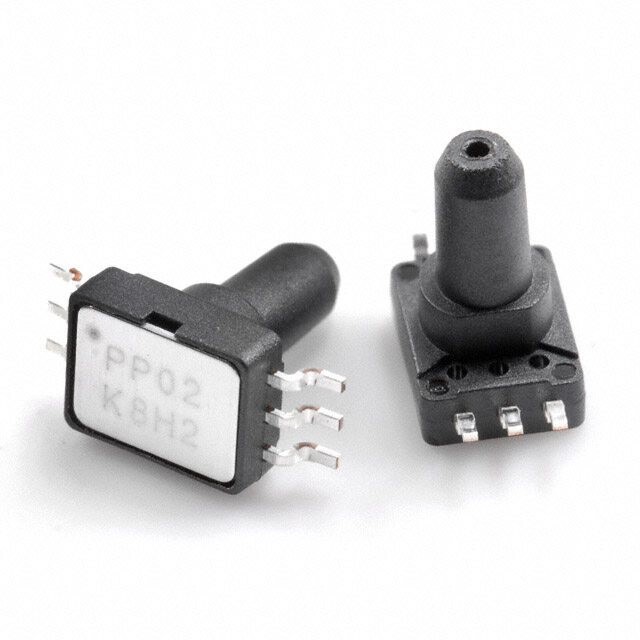
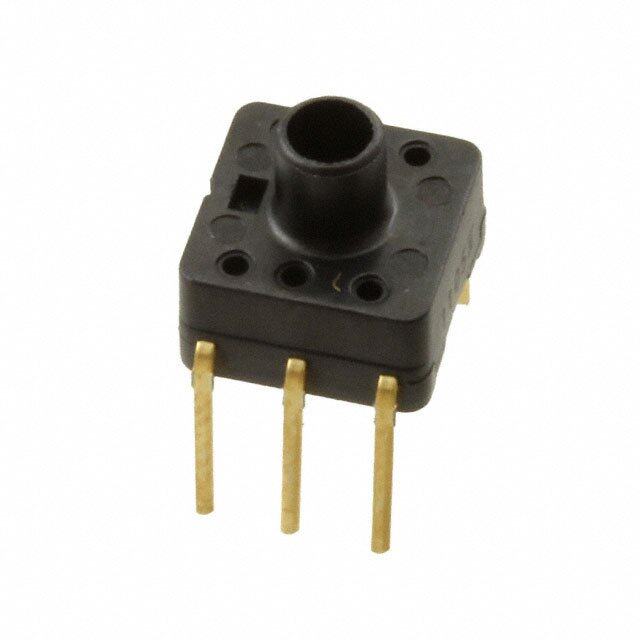
Honeywell Sensing and Productivity Solutions 的 TSCDRRN015PDUCV 是一款压力传感器/变送器,属于微型表压传感器系列,广泛应用于需要高精度、高稳定性和可靠性的工业与设备控制场景。该型号采用耐用的不锈钢结构和MEMS技术,具备良好的温度补偿性能,适用于测量正压范围(量程为0-15 psi),输出为比例电压信号。

典型应用场景包括:

1. 工业自动化:用于气动系统、液压系统或过程控制中监测压力变化,确保设备稳定运行。
2. 医疗设备:如呼吸机、麻醉机、输液泵等,对气体或液体压力进行精确监控,保障患者安全。
3. HVAC系统:用于楼宇通风、空调系统中的风压检测,优化空气流动与能效管理。
4. 测试与测量仪器:集成于便携式压力校准仪或数据采集系统中,提供可靠的测量基准。
5. 交通运输:在车辆制动系统、发动机管理系统中监测压力参数,提升运行效率与安全性。

该传感器具有紧凑尺寸、抗振动、耐腐蚀等特点,适合空间受限且环境较严苛的应用场合。其长期稳定性与低迟滞特性也使其成为高要求闭环控制系统中的理想选择。
| 参数 | 数值 |
| 产品目录 | |
| 描述 | SENSOR PRESS DIFFERENTIAL板机接口压力传感器 DIP DualRadBarb Same Side +/-15 psi Diff |
| 产品分类 | |
| 品牌 | Honeywell |
| 产品手册 | http://sensing.honeywell.com/index.php?ci_id=142173 |
| 产品图片 |
|
| rohs | 符合RoHS无铅 / 符合限制有害物质指令(RoHS)规范要求 |
| 产品系列 | 板机接口压力传感器,Honeywell TSCDRRN015PDUCVTSC |
| 数据手册 | |
| 产品型号 | TSCDRRN015PDUCV |
| 产品种类 | 板机接口压力传感器 |
| 其它名称 | 480-5825 |
| 准确性 | 0.15 % |
| 出厂设置 | - |
| 压力类型 | Differential |
| 商标 | Honeywell |
| 安装风格 | Through Hole |
| 封装 | Blister Card |
| 封装/外壳 | 8-DIP (0.524",13.30mm),双端口,同侧 |
| 封装/箱体 | DIP |
| 工作压力 | +/- 15 psi |
| 工作温度 | -40°C ~ 85°C |
| 工作电源电压 | 5 V |
| 最大工作温度 | + 85 C |
| 最小工作温度 | 0 C |
| 标准包装 | 25 |
| 特色产品 | http://www.digikey.cn/product-highlights/cn/zh/honeywell-trustability-pressure-sensors/637 |
| 电压-电源 | 1.5 V ~ 12 V |
| 电源电压-最大 | 12 V |
| 电源电压-最小 | 1.5 V |
| 电源电流 | 0.6 mA |
| 端口尺寸 | 公型,0.076"(1.93mm)双管 |
| 端口类型 | Dual Radial Barbed, Same Side |
| 端子类型 | 通孔 |
| 精度 | ±0.15%FSS |
| 输出 | 模拟,比率 |
| 输出类型 | Analog |


- 商务部:美国ITC正式对集成电路等产品启动337调查
- 曝三星4nm工艺存在良率问题 高通将骁龙8 Gen1或转产台积电
- 太阳诱电将投资9.5亿元在常州建新厂生产MLCC 预计2023年完工
- 英特尔发布欧洲新工厂建设计划 深化IDM 2.0 战略
- 台积电先进制程称霸业界 有大客户加持明年业绩稳了
- 达到5530亿美元!SIA预计今年全球半导体销售额将创下新高
- 英特尔拟将自动驾驶子公司Mobileye上市 估值或超500亿美元
- 三星加码芯片和SET,合并消费电子和移动部门,撤换高东真等 CEO
- 三星电子宣布重大人事变动 还合并消费电子和移动部门
- 海关总署:前11个月进口集成电路产品价值2.52万亿元 增长14.8%
PDF Datasheet 数据手册内容提取
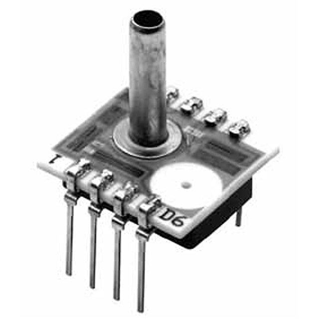
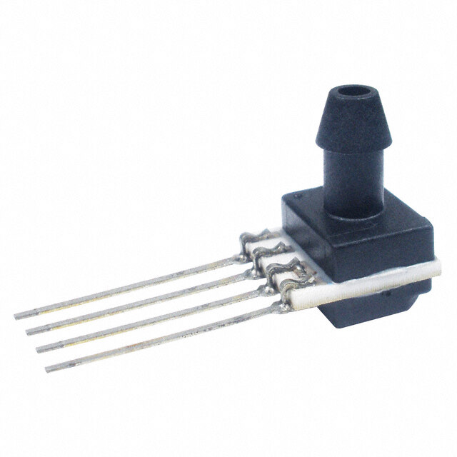
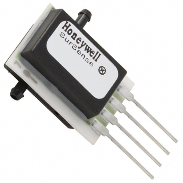
TruStability® Board Mount Pressure Sensors TSC Series, Compensated/Unamplified ±60 mbar to ±10 bar | ±6 kPa to ±1 MPa | ±1 psi to ±150 psi Millivolt Analog Output NSC Series, Uncompensated/Unamplified ±2.5 mbar to ±10 bar | ±250 Pa to ±1 MPa | ±1 inH O to ±150 psi 2 Millivolt Analog Output Datasheet
TruStability® Board Mount Pressure Sensors Honeywell’s TruStability® TSC Series and NSC Series are piezoresistive silicon pressure sensors offering a ratiometric analog output for reading pressure over the specified full scale pressure span and temperature range. TSC Series: • Temperature compensated and unamplified. • Compensation makes it easier to integrate the sensor into a system by eliminating the need to calibrate the system over temperature and also offers reduced part-to-part variation. • Compensated temperature range is 0 °C to 85 °C [-32 °F to 185 °F]. • Operating temperature range is -40 °C to 85 °C [-40 °F to 185 °F]. • Measures differential or gage pressures NSC Series: • Uncompensated and unamplified. • Allows customers the flexibility of performing their own calibration while still benefiting from the industry-leading stability, accuracy, and repeatability that the Honeywell TruStability® Pressure Sensors provide. • Operates as specified from -40 °C to 85 °C [-40 °F to 185 °F]. • Measures absolute, differential or gage pressures. The absolute versions have an internal vacuum reference and an output value proportional to absolute pressure. Differential versions allow measurement of pressure between two pressure ports. Gage versions are referenced to atmospheric pressure and provide an output proportional to pressure variations from atmosphere. The TSC Series and NSC Series sensors are intended for use with non-corrosive, non-ionic gases, such as air. Port 1 can also be used for non-corrosive, non-ionic liquids on sensors rated above 60 mbar | 6 kPa | 1 psi. The TSC and NSC Series offer numerous package styles and mounting options, making it easier for device manufacturers to integrate the product into their applications. These sensors offer infinite resolution on the pressure signal. Frequency response is also typically limited only by the end user’s system. All products are designed and manufactured according to ISO 9001. , What makes our sensors better? Table of Contents Features and Benefits .................. 3-4 • Stability and reliability you can count on Potential Applications ....................5 • Industry-leading accuracy down to ±0.15 %FSS BFSL TSC Series and NSC Series General Specifications ........................ 6-7 • Port and housing options simplify integration TSC Series Nomenclature and Order Guide ..8 • Wide pressure range from ±2.5 mbar to ±10 bar | NSC Series Nomenclature and Order Guide ..9 TSC Series Pressure Range Specifications ±250 Pa to ±1 MPa | ±1 inH O to ±150 psi 2 ±60 mbar to ±10 bar ..................10 • Small package size ±6 kPa to ±1 MPa .....................11 ±1 psi to ±150 psi .....................12 • Low power consumption NSC Series Pressure Range Specifications ±2.5 mbar to ±10 bar ..................13 ±250 Pa to ±1 MPa ....................14 ±1 inH O to ±150 psi ..................15 2 Available Standard Configurations .......16-17 Dimensional Drawings DIP Packages ..................... 18-20 SMT Packages ................... 21-23 SIP Packages ..................... 24-28 Pinouts, PCB Layouts, Circuit Examples ....29 TruStability® Board Mount Pressure Sensors Portfolio Overview ..............30 Additional Information. . . . . . . . . . . .back cover stability • accuracy • flexibility • small size 2 sensing.honeywell.com
Features INdUSTry-leadINg loNg-Term STabIlITy and Benefits Even after long-term use and thermal extremes, these sensors perform substantially better relative to stability than any other pressure sensor available in the industry today: • Minimizes system calibration needs and maximizes system performance. • Helps support system uptime by eliminating the need to service or replace the sensor during its application life. INdUSTry-leadINg aCCUraCy Extremely tight accuracy down to ±0.15 %FSS BFSL: • Reduces software needed to correct system inaccuracies, minimizing system design time. • Supports system accuracy and warranty requirements. Minimizes system calibration and design needs; supports system uptime. INdUSTry-leadINg flexIbIlITy • Modular, flexible design with numerous package styles, pressure ports, and options simplifies integration into the device manufacturer’s application. • Single side wet media allows the end customer to use one port of the sensor with condensing humidity or directly with non-corrosive liquid media. Simplifies product integration. INSeNSITIve To moUNTINg orIeNTaTIoN Allows flexibility of use within the application. Small SIze Miniature 10 mm x 10 mm [0.39 in x 0.39 in] package is very small when compared to most board mount pressure sensors: • Occupies less area on the PCB. • Typically allows for easy placement on crowded PCBs or in small devices. repeaTabIlITy Provides excellent repeatability, high accuracy and reliability under many demanding conditions. SUpporTS leaN maNUfaCTUrINg • J-STD-020-D MSL 1 unlimited shelf life after packaging is opened. • System can be calibrated within one hour after reflow solder. • Compatible with modern lead-free and no-clean solder processes. sensing.honeywell.com 3
Features exTremely low power CoNSUmpTIoN and Benefits • Operating supply voltage as low as 1.5 Vdc. • Reduces power consumption, provides extended battery life, and promotes energy efficiency. abSolUTe, dIffereNTIal aNd gage TypeS • Provides flexibility of use within the application. • Absolute type on NSC Series only. preSSUre raNgeS from ±2.5 mbar To ±10 bar | ±250 pa To ±1 mpa | ±1 INH o To ±150 pSI 2 Optimizes the customer’s system performance by maximizing pressure resolution with more available pressure ranges. roHS aNd ISo9001 ComplIaNCe 4 sensing.honeywell.com
Potential Applications medICal • NebUlIzerS • SpIromeTerS • paTIeNT moNITorINg eQUIpmeNT • THerapeUTIC HoSpITal bedS • HoSpITal gaS SUpply • oxygeN CoNCeNTraTorS • blood aNalySIS • gaS CHromaTograpHy • aNalyTICal INSTrUmeNTS INdUSTrIal • valveS • pUmpS • aCTUaTorS • HvaC TraNSmITTerS • aUTomaTed pNeUmaTIC aSSembly eQUIpmeNT • pNeUmaTIC operaTor CoNTrol SySTemS • INdUSTrIal gaS SUpply • baromeTry • gaS CHromaTograpHy • aNalyTICal INSTrUmeNT SamplINg SySTemS sensing.honeywell.com 5
TSC Series and NSC Series General Specifications Table 1. absolute maximum ratings1 Characteristic min. max. Unit Supply voltage (V )2: supply pressure ranges >60 mbar | 6 kPa | 1 psi -12.0 12.0 Vdc pressure ranges <40 mbar | 4 kPa | 20 inHO 0 7 2 Storage temperature -40 [-40] 85 [185] °C [°F] Soldering time and temperature: lead solder temperature (SIP, DIP) 4 s max. at 250 °C [482 °F] peak reflow temperature (SMT) 15 s max. at 250 °C [482 °F] 1Absolute maximum ratings are the extreme limits the device will withstand without damage. 2Incorrect application of supply voltage or ground to the wrong pin may cause electrical failure. Table 2. operating Specifications Characteristic min. Typ. max. Unit Supply voltage (V ):1, 2 supply pressure ranges >60 mbar | 6 kPa | 1 psi 1.5 5.0 12.0 Vdc pressure ranges <40 mbar | 4 kPa | 20 HO 2.7 5.0 6.5 2 Supply current (at 5.0 Vdc supply) TSC Series — 0.6 1 mA NSC Series — 1.5 2.2 Operating temperature range3 -40 [-40] — 85 [185] °C [°F] TSC Series compensated temperature range4 0 [32] — 85 [185] °C [°F] Startup time — — 5 ms TSC Series output resistance — 2.5 — kOhm 1Ratiometricity of the sensor (the ability of the device output to scale to the supply voltage) is achieved within the specified operating voltage. 2Incorrect application of supply voltage or ground to the wrong pin may cause electrical failure. 3Operating temperature range: The temperature range over which the sensor will produce an output proportional to pressure. 4Compensated temperature range: The temperature range over which the sensor will produce an output proportional to pressure within the specified performance limits. Table 3. environmental Specifications Characteristic parameter Humidity 0% to 95% RH, non-condensing Vibration MIL-STD-202G, Method 204D, Condition B (15 g, 10 Hz to 2 kHz) Shock MIL-STD-202G, Method 213B, Condition C (100 g, 6 ms duration) Life1 1 million pressure cycles minimum Solder reflow J-STD-020-D MSL1 (unlimited shelf life when stored at less than 30 °C and 85 %RH) 1Life may vary depending on the specific application in which the sensor is utilized. 6 sensing.honeywell.com
TSC Series and NSC Series General Specifications Table 4. wetted materials1 Component port 1 (pressure port) port 2 (reference port) Ports and covers high temperature polyamide high temperature polyamide Substrate alumina ceramic alumina ceramic Adhesives epoxy, RTV epoxy, RTV Electronic components silicon silicon, glass, gold 1Contact Honeywell Customer Service for detailed material information. CAUTION PRODUCT DAMAGE • Ensure liquid media is applied to Port 1 only; Port 2 is not compatible with liquids. • Ensure liquid media contains no particulates. All TruStability® sensors are dead-ended devices. Particulates can accumulate inside the sensor, causing damage or affecting sensor output. • Recommend that the sensor be positioned with Port 1 facing downwards; any particulates in the system are less likely to enter and settle within the pressure sensor if it is in this position. • Ensure liquid media does not create a residue when dried; build-up inside the sensor may affect sensor output. Rinsing of a dead-ended sensor is difficult and has limited effectiveness for removing residue. • Ensure liquid media are compatible with wetted materials. Non-compatible liquid media will degrade sensor performance and may lead to sensor failure. Failure to comply with these instructions may result in product damage. Table 5. Sensor pressure Types pressure Type description Absolute Output is proportional to the difference between applied pressure and a built-in reference to vacuum. Differential Output is proportional to the difference between the pressures applied to each port (Port 1 – Port 2). Gage Output is proportional to the difference between applied pressure and atmospheric (ambient) pressure. sensing.honeywell.com 7
TSC Series Nomenclature and Order Guide figure 1. TSC Series Nomenclature and order guide1 For example, TSCDNNN150PGUCV defines a TSC Series TruStability® Pressure Sensor, DIP package, NN pressure port, no special options,150 psi gage pressure range, unamplified, compensated, constant supply voltage. T S C D N N N 1 5 0 P G U C V Series Supply Voltage TSC Compensated/Unamplified V Constant Package Compensation D DIP (Dual Inline Pin) C Compensated M SMT (Surface Mount Technology) S SIP (Single Inline Pin) Output Type U Unamplified Pressure Port Pressure Range DIP SMT SIP 60 mbar to 10 bar 6 kPa to 1 MPa 1 psi to 150 psi NN No ports NN No ports NN No ports Differential Differential Differential 060MD ±60 mbar 006KD±6 kPa 001PD ±1 psi AA Dbaurable adx ipaolrts, 100MD ±100 mbar 010KD±10 kPa 005PD ±5 psi opposite sides 160MD ±160 mbar 016KD±16 kPa 015PD ±15 psi 250MD ±250 mbar 025KD±25 kPa 030PD ±30 psi AN Sbainrgbleed a pxoiartl AN Sbainrgbleed a pxoiartl AN Sbainrgbleed a pxoiartl 400MD ±400 mbar 040KD±40 kPa 060PD ±60 psi 600MD ±600 mbar 060KD±60 kPa 100PD ±100 psi LN Sbainrgbllees asx piaol rt LN Sbainrgbllees asx piaol rt LN Sbainrgbllees asx piaol rt 010.61BBDD ±±11. 6b abrar 110600KKDD±±110600 kkPPaa 150PD ±150 psi 2.5BD ±2.5 bar 250KD±250 kPa FF Fmaxaoisautlen bnt,ae drrbueadl 004BD ±4 bar 400KD ±400 kPa ports, opposite 006BD ±6 bar 600KD ±600 kPa sides 010BD ±10 bar 001GD ±1 MPa Fastener FN maxoiauln bt,a srbinegdle Gage Gage Gage port 060MG 0 mbar to 60 mbar 006KG0 kPa to 6 kPa 001PG 0 psi to 1 psi Ribbed 100MG 0 mbar to 100 mbar 010KG0 kPa to 10 kPa 005PG0 psi to 5 psi GNfastener mount, sbianrgbleed a pxioa0rlt08B 160MG 0 mbar to 160 mbar 016KG0 kPa to 16 kPa 015PG0 psi to 15 psi 250MG 0 mbar to 250 mbar 025KG0 kPa to 25 kPa 030PG 0 psi to 30 psi Fastener NB mount, dual 400MG 0 bar to 400 mbar 040KG0 kPa to 40 kPa 060PG 0 psi to 60 psi asaximale p soidrtes, 600MG 0 bar to 600 mbar 060KG0 kPa to 60 kPa 100PG 0 psi to 100 psi 001BG 0 bar to 1 bar 100KG0 kPa to 100 kPa 150PG 0 psi to 150 psi RN Single radial RN Single radial RN Single radial 1.6BG 0 bar to 1.6 bar 160KG0 kPa to 160 kPa barbed port barbed port barbed port 2.5BG 0 bar to 2.5 bar 250KG0 kPa to 250 kPa Dual radial Dual radial Dual radial 004BG 0 bar to 4 bar 400KG0 kPa to 400 kPa RR bsaamrbee ds ipdoerts, RR bsaamrbee ds ipdoerts, RR sbaamrbee ds ipdoerts, 006BG 0 bar to 6 bar 600KG0 kPa to 600 kPa 010BG 0 bar to 10 bar 001GG0 kPa to 1 MPa Dual radial Dual radial Dual radial DR barbed ports, DR barbed ports, DR barbed ports, opposite sides opposite sides opposite sides JN Sbainrgbllees rsa dpioarlt JN Sbainrgbllees rsa dpioarlt JN Sbainrgbllees rsa dpioarlt Dual radial Dual radial Dual radial JJ barbless ports, JJ barbless ports, JJ barbless ports, same side same side same side Fastener HHmraoduianl tb, adrubaeld ports, same side Fastener HNmount, single radial barbed port Manifold MNmount, outer diameter seal Manifold SN mount, inner diameter seal Options N No special options 1See Table 5 for an explanation of sensor pressure types. 8 sensing.honeywell.com
NSC Series Nomenclature and Order Guide figure 2. NSC Series Nomenclature and order guide1 For example, NSCDNNN150PGUNV defines an NSC Series TruStability® Pressure Sensor, DIP package, NN pressure port, no special options,150 psi gage pressure range, unamplified, uncompensated, constant supply voltage. N S C D N N N 1 5 0 P G U N V Supply Voltage Series V Constant NSC Uncompensated/Unamplified Compensation Package N Uncompensated D DIP (Dual Inline Pin) M SMT (Surface Mount Technology) Output Type S SIP (Single Inline Pin) U Unamplified Pressure Port Pressure Range DIP SMT SIP 2.5 mbar to 10 bar 400 Pa to 1 MPa 1 in H2O to 150 psi NN No ports NN No ports NN No ports Absolute Absolute Absolute 001BA 0 bar to 1 bar 100KA 0 kPa to 100 kPa 015PA0 psi to 15 psi Dual axial 1.6BA 0 bar to 1.6 bar 160KA 0 kPa to 160 kPa 030PA0 psi to 30 psi AA barbed ports, 2.5BA 0 bar to 2.5 bar 250KA 0 kPa to 250 kPa 060PA0 psi to 60 psi opposite sides 004BA 0 bar to 4 bar 400KA 0 kPa to 400 kPa 100PA0 psi to 100 psi AN Sbainrgbleed a pxoiartl AN Sbainrgbleed a pxoiartl AN Sbainrgbleed a pxoiartl 000160BBAA 00 bbaarr ttoo 610 b baarr 600001KGAA 00 kkPPaa ttoo 610 M0P kaPa 150PA0 psi to 150 psi Differential Differential Differential LN Sbainrgbllees asx piaol rt LN Sbainrgbllees asx piaol rt LN Sbainrgbllees asx piaol rt 2.5MD ±2.5 mbar 250LD ±250 Pa 001ND ±1 inH2O 004MD ±4 mbar 400LD ±400 Pa 002ND±2 inH2O FF Fmapxoaoirsauttslen ,bnt ,oae dprrbupeaodls ite 000160MMDD ±±610 m mbbaarr 600001LKDD ±±610 k0P Paa 000045NNDD ±±45 iinnHH22OO sides 016MD ±16 mbar 1.6KD ±1.6 kPa 010ND±10 inH2O FN Fmaosutennt,e sringle 025MD ±25 mbar 2.5KD ±2.5 kPa 020ND ±20 inH2O apxoiratl barbed 040MD ±40 mbar 004KD±4 kPa 030ND ±30 inH2O 060MD ±60 mbar 006KD±6 kPa 001PD ±1 psi Ribbed GNfastener mount, 100MD ±100 mbar 010KD±10 kPa 005PD ±5 psi single axial barbed po0rt08B 160MD ±160 mbar 016KD±16 kPa 015PD ±15 psi Fastener 250MD ±250 mbar 025KD±25 kPa 030PD ±30 psi NB maxoiauln pt,o drtusa, l 400MD ±400 mbar 040KD±40 kPa 060PD ±60 psi same side 600MD ±600 mbar 060KD±60 kPa 100PD ±100 psi 001BD ±1 bar 100KD±100 kPa 150PD ±150 psi RN Sbainrgbleed r apdoiratl RN Sbainrgbleed r apdoiratl RN Sbainrgbleed r apdoiratl 1.6BD ±1.6 bar 160KD±160 kPa 2.5BD ±2.5 bar 250KD±250 kPa Dual radial Dual radial Dual radial 004BD ±4 bar 400KD ±400 kPa RR barbed ports, RR barbed ports, RR barbed ports, same side same side same side 006BD ±6 bar 600KD ±600 kPa 010BD ±10 bar 001GD ±1 MPa Dual radial Dual radial Dual radial DR barbed ports, DR barbed ports, DR barbed ports, Gage Gage Gage opposite sides opposite sides opposite sides 004MG 0 mbar to 4 mbar 400LG0 Pa to 400 Pa 002NG0 inH2O to 2 inH2O JN Sbainrgbllees rsa dpioarlt JN Sbainrgbllees rsa dpioarlt JN Sbainrgbllees rsa dpioarlt 000160MMGG 00 mmbbaarr ttoo 610 m mbbaarr 600001LKGG00 PkPaa t oto 6 10 0k PPaa 000045NNGG00 iinnHH22OO ttoo 45 iinnHH22OO 016MG 0 mbar to 16 mbar 1.6KG 0 kPa to 1.6 kPa 010NG 0 inH2O to 10 inH2O JJ Dbaurabll erasds iaplorts, JJ Dbaurabll erasds iaplorts, JJ Dbaurabll erasds iaplorts, 025MG 0 mbar to 25 mbar 004KG0 kPa to 4 kPa 020NG0 inH2O to 20 inH2O same side same side same side 040MG 0 mbar to 40 mbar 006KG0 kPa to 6 kPa 030NG0 inH2O to 30 inH2O Fastener 060MG 0 mbar to 60 mbar 010KG0 kPa to 10 kPa 001PG 0 psi to 1 psi HHmraoduianl tb, adrubaeld 100MG 0 mbar to 100 mbar 016KG0 kPa to 16 kPa 005PG0 psi to 5 psi psiodrets, same 160MG 0 mbar to 160 mbar 025KG0 kPa to 25 kPa 015PG0 psi to 15 psi Fastener 250MG 0 mbar to 250 mbar 040KG0 kPa to 40 kPa 030PG 0 psi to 30 psi HNmraoduianl tb, asirnbgelde 400MG 0 bar to 400 mbar 060KG0 kPa to 60 kPa 060PG 0 psi to 60 psi port 600MG 0 bar to 600 mbar 100KG0 kPa to 100 kPa 100PG 0 psi to 100 psi Manifold 001BG 0 bar to 1 bar 160KG0 kPa to 160 kPa 150PG 0 psi to 150 psi MNmount, outer diameter seal 1.6BG 0 bar to 1.6 bar 250KG0 kPa to 250 kPa 2.5BG 0 bar to 2.5 bar 400KG0 kPa to 400 kPa SN Mmaonuinfot,l dinner 004BG 0 bar to 4 bar 600KG0 kPa to 600 kPa diameter seal 006BG 0 bar to 6 bar 001GG0 kPa to 1 MPa 010BG 0 bar to 10 bar Options N No special options 1See Table 5 for an explanation of sensor pressure types. sensing.honeywell.com 9
TSC Series Specifications ±60 mbar to ±10 bar Table 6. TSC Series pressure range Specifications for ±60 mbar to ±10 bar pressure range order Code (see figure 1) pmpirrnea.snsgpuemrea x. Unit over pressure burst pressure Common mode pressure pressure accuracy(%fSS) o(mffvs/evt)1 min.full S(mcaNom.vl/ev S)panmax. T 15h00toe o °°nr(CC%m o fafSlf se S8e0f)5tft °oe2 C °cC t T 15h00te o o°°r(CnC%m SfapSl aeS80nf)5tf 3° oe °CcC t long-Term Stability1000 hr, 25 °C(%fSS) 4Thermal Hysteresis (%fSS) differential 060MD -60 60 mbar 872 1370 10,000 ±0.20 ±0.075 2.46 2.60 2.80 ±0.60 ±1.15 ±1.00 ±2.00 ±0.15 ±0.15 100MD -100 100 mbar 872 1370 10,000 ±0.20 ±0.075 4.12 4.40 4.66 ±0.35 ±0.70 ±1.00 ±2.00 ±0.10 ±0.10 160MD -160 160 mbar 2000 4000 10,000 ±0.15 ±0.12 4.36 4.60 4.92 ±0.80 ±1.65 ±0.75 ±2.00 ±0.10 ±0.10 250MD -250 250 mbar 2000 4000 10,000 ±0.15 ±0.12 6.82 7.30 7.70 ±0.55 ±1.05 ±0.75 ±2.00 ±0.10 ±0.10 400MD -400 400 mbar 2000 4000 10,000 ±0.15 ±0.12 10.90 11.60 12.30 ±0.35 ±0.65 ±0.75 ±2.00 ±0.10 ±0.10 600MD -600 600 mbar 4000 8000 10,000 ±0.15 ±0.075 5.88 16.10 6.36 ±0.40 ±0.85 ±0.50 ±1.25 ±0.10 ±0.10 001BD -1 1 bar 4 8 10 ±0.15 ±0.075 9.80 10.20 10.60 ±0.25 ±0.50 ±0.50 ±1.25 ±0.10 ±0.10 1.6BD -1.6 1.6 bar 4 8 10 ±0.15 ±0.075 15.68 16.30 16.96 ±0.15 ±0.30 ±0.50 ±1.25 ±0.10 ±0.10 2.5BD -2.5 2.5 bar 8 17 10 ±0.15 ±0.075 12.20 12.70 13.18 ±0.20 ±0.40 ±0.50 ±1.50 ±0.10 ±0.10 004BD -4 4 bar 10 17 15 ±0.15 ±0.075 11.14 11.60 12.08 ±0.25 ±0.50 ±0.50 ±1.25 ±0.10 ±0.10 006BD -6 6 bar 17 17 15 ±0.15 ±0.075 10.16 10.60 11.08 ±0.35 ±0.50 ±0.50 ±1.00 ±0.10 ±0.10 010BD -10 10 bar 17 17 15 ±0.15 ±0.075 16.94 17.70 18.44 ±0.20 ±0.3 ±0.5 ±1.00 ±0.10 ±0.10 gage 060MG 0 60 mbar 872 1370 10,000 ±0.20 ±0.075 1.23 1.30 1.40 ±1.15 ±2.35 ±1.00 ±2.00 ±0.30 ±0.30 100MG 0 100 mbar 872 1370 10,000 ±0.20 ±0.075 2.06 2.20 2.33 ±0.70 ±1.40 ±1.00 ±2.00 ±0.20 ±0.20 160MG 0 160 mbar 2000 4000 10,000 ±0.15 ±0.12 2.18 2.30 2.46 ±1.65 ±3.30 ±0.75 ±2.00 ±0.20 ±0.20 250MG 0 250 mbar 2000 4000 10,000 ±0.15 ±0.12 3.41 3.65 3.85 ±1.05 ±2.10 ±0.75 ±2.00 ±0.15 ±0.15 400MG 0 400 mbar 2000 4000 10,000 ±0.15 ±0.12 5.45 5.80 6.15 ±0.65 ±1.30 ±0.75 ±2.00 ±0.10 ±0.10 600MG 0 600 mbar 4000 8000 10,000 ±0.15 ±0.075 2.94 3.05 3.18 ±0.85 ±1.65 ±0.50 ±1.25 ±0.15 ±0.15 001BG 0 1 bar 4 8 10 ±0.15 ±0.075 4.90 5.10 5.30 ±0.50 ±1.00 ±0.50 ±1.25 ±0.10 ±0.10 1.6BG 0 1.6 bar 4 8 10 ±0.15 ±0.075 7.84 8.15 8.48 ±0.30 ±0.65 ±0.50 ±1.25 ±0.10 ±0.10 2.5BG 0 2.5 bar 8 17 10 ±0.15 ±0.075 6.10 6.35 6.59 ±0.40 ±0.80 ±0.50 ±1.50 ±0.10 ±0.10 004BG 0 4 bar 10 17 15 ±0.15 ±0.075 5.57 5.80 6.04 ±0.50 ±1.00 ±0.50 ±1.25 ±0.10 ±0.10 006BG 0 6 bar 17 17 15 ±0.15 ±0.075 5.08 5.30 5.54 ±0.65 ±1.00 ±0.50 ±1.00 ±0.15 ±0.15 010BG 0 10 bar 17 17 15 ±0.15 ±0.075 8.47 8.85 9.22 ±0.40 ±0.60 ±0.50 ±1.00 ±0.10 ±0.10 1Offset: The output signal obtained when the reference pressure is applied to all available pressure ports. Also known as “null” or “zero”. 2Thermal effect on offset: The deviation in offset due to changes in temperature over the compensated temperature range, relative to offset measured at 25 ºC. 3Thermal effect on span: The deviation in full scale span due to changes in temperature over the compensated temperature range, relative to full sca le span measured at 25 ºC. 4Thermal hysteresis: The maximum difference between output readings when the same temperature is reached consecutively, under the sam e operating conditions, with temperature approaching from opposite directions within the operating temperature range. Validated over the full operatin g temperature and pressure ranges using a ~5 ºC/minute ramp and 30 minute dwell. Application performance may be affected by the thermal mass of the end user system. 10 sensing.honeywell.com
TSC Series Specifications ±6 kPa to ±1 MPa Table 7. TSC Series pressure range Specifications for ±6 kpa to ±1 mpa pressure range order Code (see figure 1) pmpirrnea.snsgpuemrea x. Unit over pressure burst pressure Common mode pressure pressure accuracy(%fSS) o(mffvs/evt)1 min.full S(mcaNom.vl/ev S)panmax. T 15h00toe o °°nr(CC%m o fafSlf se S8e0f)5tf t°oe2 C° cC t T 15h00te oo °°r(CnC%m SfapSl aeS80nf)5tf 3° oe °CcC t long-Term Stability1000 hr, 25 °C(%fSS) 4 Thermal Hysteresis(%fSS) differential 006KD -6 6 kPa 87 137 1000 ±0.20 ±0.075 2.46 2.60 2.80 ±0.60 ±1.15 ±1.00 ±2.00 ±0.15 ±0.15 010KD -10 10 kPa 87 137 1000 ±0.20 ±0.075 4.12 4.40 4.66 ±0.35 ±0.70 ±1.00 ±2.00 ±0.10 ±0.10 016KD -16 16 kPa 200 400 1000 ±0.15 ±0.12 4.36 4.60 4.92 ±0.80 ±1.65 ±0.75 ±2.00 ±0.10 ±0.10 025KD -25 25 kPa 200 400 1000 ±0.15 ±0.12 6.82 7.30 7.70 ±0.55 ±1.05 ±0.75 ±2.00 ±0.10 ±0.10 040KD -40 40 kPa 200 400 1000 ±0.15 ±0.12 10.90 11.60 12.30 ±0.35 ±0.65 ±0.75 ±2.00 ±0.10 ±0.10 060KD -60 60 kPa 400 800 1000 ±0.15 ±0.075 5.88 16.10 6.36 ±0.40 ±0.85 ±0.50 ±1.25 ±0.10 ±0.10 100KD -100 100 kPa 400 800 1000 ±0.15 ±0.075 9.80 10.20 10.60 ±0.25 ±0.50 ±0.50 ±1.25 ±0.10 ±0.10 160KD -160 160 kPa 400 800 1000 ±0.15 ±0.075 15.68 16.30 16.96 ±0.15 ±0.30 ±0.50 ±1.25 ±0.10 ±0.10 250KD -250 250 kPa 800 1700 1000 ±0.15 ±0.075 12.20 12.70 13.18 ±0.20 ±0.40 ±0.50 ±1.50 ±0.10 ±0.10 400KD -400 400 kPa 1000 1700 1600 ±0.15 ±0.075 11.14 11.60 12.08 ±0.25 ±0.50 ±0.50 ±1.25 ±0.10 ±0.10 600KD -600 600 kPa 1700 1700 1700 ±0.15 ±0.075 10.16 10.60 11.08 ±0.35 ±0.50 ±0.50 ±1.00 ±0.10 ±0.10 001GD -1 1 MPa 1.70 1.70 1.7 ±0.15 ±0.075 16.94 17.70 18.44 ±0.20 ±0.30 ±0.50 ±1.00 ±0.10 ±0.10 gage 006KG 0 6 kPa 87 137 1000 ±0.20 ±0.075 1.23 1.30 1.40 ±1.15 ±2.35 ±1.00 ±2.00 ±0.30 ±0.30 010KG 0 10 kPa 87 137 1000 ±0.20 ±0.075 2.06 2.20 2.33 ±0.70 ±1.40 ±1.00 ±2.00 ±0.20 ±0.20 016KG 0 16 kPa 200 400 1000 ±0.15 ±0.12 2.18 2.30 2.46 ±1.65 ±3.30 ±0.75 ±2.00 ±0.20 ±0.20 025KG 0 25 kPa 200 400 1000 ±0.15 ±0.12 3.41 3.65 3.85 ±1.05 ±2.10 ±0.75 ±2.00 ±0.15 ±0.15 040KG 0 40 kPa 200 400 1000 ±0.15 ±0.12 5.45 5.80 6.15 ±0.65 ±1.30 ±0.75 ±2.00 ±0.10 ±0.10 060KG 0 60 kPa 400 800 1000 ±0.15 ±0.075 2.94 3.05 3.18 ±0.85 ±1.65 ±0.50 ±1.25 ±0.15 ±0.15 100KG 0 100 kPa 400 800 1000 ±0.15 ±0.075 4.90 5.10 5.30 ±0.50 ±1.00 ±0.50 ±1.25 ±0.10 ±0.10 160KG 0 160 kPa 400 800 1000 ±0.15 ±0.075 7.84 8.15 8.48 ±0.30 ±0.65 ±0.50 ±1.25 ±0.10 ±0.10 250KG 0 250 kPa 800 1700 1000 ±0.15 ±0.075 6.10 6.35 6.59 ±0.40 ±0.80 ±0.50 ±1.50 ±0.10 ±0.10 400KG 0 400 kPa 1000 1700 1600 ±0.15 ±0.075 5.57 5.80 6.04 ±0.50 ±1.00 ±0.50 ±1.25 ±0.10 ±0.10 600KG 0 600 kPa 1700 1700 1700 ±0.15 ±0.075 5.08 5.30 5.54 ±0.65 ±1.00 ±0.50 ±1.00 ±0.15 ±0.15 001GG 0 1 MPa 1.70 1.70 1.7 ±0.15 ±0.075 8.47 8.85 9.22 ±0.40 ±0.60 ±0.50 ±1.00 ±0.10 ±0.10 1Offset: The output signal obtained when the reference pressure is applied to all available pressure ports. Also known as “null” or “zero”. 2Thermal effect on offset: The deviation in offset due to changes in temperature over the compensated temperature range, relative to offset measured at 25 ºC. 3Thermal effect on span: The deviation in full scale span due to changes in temperature over the compensated temperature range, relative to full sca le span measured at 25 ºC. 4Thermal hysteresis: The maximum difference between output readings when the same temperature is reached consecutively, under the sam e operating conditions, with temperature approaching from opposite directions within the operating temperature range. Validated over the full operatin g temperature and pressure ranges using a ~5 ºC/minute ramp and 30 minute dwell. Application performance may be affected by the thermal mass of the end user system. sensing.honeywell.com 11
TSC Series Specifications ±1 psi to ±150 psi Table 8. TSC Series pressure range Specifications for ±1 psi to ±150 psi pressure range order Code (see figure 1) pmpirrne.asnsgpuemrea x. Unit over pressure burst pressure Common mode pressure pressure accuracy(%fSS) o(mffvs/evt)1 min.full S(mcaNom.vl/ev S)panmax. T 15h00toe o °°nr(CC%m o fafSlf se S8e0f)5tft °oe2 C °cC t T 15h00te o o°°r(CnC%m SfapSl aeS80nf)5tf 3° oe °CcC t long-Term Stability1000 hr, 25 °C(%fSS) 4Thermal Hysteresis (%fSS) differential 001PD -1 1 psi 12.5 20 145 ±0.20 ±0.075 2.84 3.00 3.22 ±0.50 ±1.00 ±1.00 ±2.00 ±0.15 ±0.15 005PD -5 5 psi 30 60 145 ±0.15 ±0.12 9.40 10.00 10.60 ±0.40 ±0.75 ±0.75 ±2.00 ±0.10 ±0.10 015PD -15 15 psi 60 115 145 ±0.15 ±0.075 10.12 10.50 10.98 ±0.25 ±0.50 ±0.50 ±1.25 ±0.10 ±0.10 030PD -30 30 psi 115 245 145 ±0.15 ±0.075 10.10 10.50 10.90 ±0.25 ±0.50 ±0.50 ±1.50 ±0.10 ±0.10 060PD -60 60 psi 145 245 230 ±0.15 ±0.075 11.52 12.00 12.48 ±0.25 ±0.50 ±0.50 ±1.25 ±0.10 ±0.10 100PD -100 100 psi 245 245 245 ±0.15 ±0.075 11.66 12.00 12.72 ±0.30 ±0.45 ±0.50 ±1.00 ±0.10 ±0.10 150PD -150 150 psi 245 245 245 ±0.15 ±0.075 17.50 18.30 19.08 ±0.20 ±0.30 ±0.50 ±1.00 ±0.10 ±0.10 gage 001PG 0 1 psi 12.7 20 145 ±0.20 ±0.075 1.42 1.50 1.61 ±1.00 ±2.05 ±1.00 ±2.00 ±0.25 ±0.25 005PG 0 5 psi 30 60 145 ±0.15 ±0.12 4.70 5.00 5.30 ±0.75 ±1.50 ±0.75 ±2.00 ±0.10 ±0.10 015PG 0 15 psi 60 115 145 ±0.15 ±0.075 5.06 5.25 5.49 ±0.50 ±0.95 ±0.50 ±1.25 ±0.10 ±0.10 030PG 0 30 psi 115 245 145 ±0.15 ±0.075 5.05 5.25 5.45 ±0.50 ±0.95 ±0.50 ±1.50 ±0.10 ±0.10 060PG 0 60 psi 145 245 230 ±0.15 ±0.075 5.76 6.00 6.24 ±0.50 ±0.95 ±0.50 ±1.25 ±0.10 ±0.10 100PG 0 100 psi 245 245 245 ±0.15 ±0.075 5.83 6.10 6.36 ±0.60 ±0.85 ±0.50 ±1.00 ±0.10 ±0.10 150PG 0 150 psi 245 245 245 ±0.15 ±0.075 8.75 9.15 9.54 ±0.40 ±0.60 ±0.50 ±1.00 ±0.10 ±0.10 1Offset: The output signal obtained when the reference pressure is applied to all available pressure ports. Also known as “null” or “zero”. 2Thermal Effect on Offset: The deviation in offset due to changes in temperature over the compensated temperature range, relative to offset measure d at 25 ºC. 3Thermal Effect on Span: The deviation in full scale span due to changes in temperature over the compensated temperature range, relative to full sca le span measured at 25 ºC. 4Thermal Hysteresis: The maximum difference between output readings when the same temperature is reached consecutively, under the sam e operating conditions, with temperature approaching from opposite directions within the operating temperature range. Validated over the full operatin g temperature and pressure ranges using a ~5 ºC/minute ramp and 30 minute dwell. Application performance may be affected by the thermal mass of the end user system. figure 3. TSC Series Typical Temperature performance The graph below indicates typical error multipliers for Thermal Effect on Offset (TEO) and Thermal Effect on Span (TES) outside the Compensated Temperature Range. See Tables 6-8 for details of the specified maximum errors within the Compensated Temperature Range. 4 3 r e pli S 2 Multi d TE 1 Operating Temperature Range r n o a 0 al Err TEO -1 Compensated Temperature Range c r pi fo -2 y T -3 -4 -40 -20 0 10 50 85 [-40] [-4] [32] [50] [122] [185] Temperature (°C [°F]) 12 sensing.honeywell.com
NSC Series Specifications ±2.5 mbar to ±10 bar Table 9. NSC Series pressure range Specifications for ±2.5 mbar to ±10 bar pressure range order Code (see figure 2) pmin.pressure rangepmax. Unit working pressure over pressure burst pressure Common mode pressure min. o(mffNom.vs/evt1)max. min.fu(mSll pNom.vSa/cvna)lemax. (min.%fTSCSNom./o225 ºmax.C) (min.%fTSCSNom./S235 ºmax.C) min.re(skIniosNom.pthaumntc)emax.4 (min.-40(p ºCpTCm Nom.tor/ °25C5) ºCmax.) (min.25( pºCpT CmtNom.or/ 8°5C5 )ºmax.C) long-Term Stability1000 hr, 25 °C(%fSS)accuracy (%fSS) absolute 001BA 0 1 bar - 2 4.1 N/A -6.0 0.0 6.0 10.0 14.5 19.0 -3.8 0.0 3.8 -7.5 -5 -3.0 2.6 3.5 4.4 500 1000 1500 1500 20002500±0.25±0.25 1.6BA 0 1.6 bar - 4.1 8 N/A -6.0 0.0 6.0 7.7 11.4 15.2 -4.9 0.0 4.9 -7.5 -5 -3.0 2.6 3.5 4.4 500 1000 1500 1500 20002500±0.25±0.25 2.5BA 0 2.5 bar - 4.1 8 N/A -6.0 0.0 6.0 12.0 17.9 23.8 -3.1 0.0 3.1 -7.5 -5 -3.0 2.6 3.5 4.4 500 1000 1500 1500 20002500±0.20±0.25 004BA 0 4 bar - 8 17 N/A -6.0 0 6.0 10.3 14.7 19.0 -3.6 0.0 3.6 -7.5 -5 -3.0 2.6 3.5 4.4 500 1000 1500 1500 20002500±0.25±0.25 006BA 0 6 bar - 17 17 N/A -6.0 0.0 6.0 7.9 11.0 14.0 -4.8 0.0 4.8 -7.5 -5 -3.0 2.6 3.5 4.4 500 1000 1500 1500 20002500±0.25±0.25 010BA 0 10 bar - 17 17 N/A -6.0 0.0 6.0 13.2 18.3 23.4 -2.9 0.0 2.9 -7.5 -5 -3.0 2.6 3.5 4.4 500 1000 1500 1500 20002500±0.20±0.25 differential 2.5MD -2.5 2.5 mbar 335 675 1000 3450 -24 -4 16 10.5 15.8 21. -3.0 5.1 13.3 -8.9 -6 -3.8 2.5 3.3 4 1800 2175 2550 1300 1525 1750±0.50±0.25 004MD -4 4 mbar 335 675 1000 3450 -24 -4 16 16.9 25.3 33.7 -1.9 3.2 8.3 -8.9 -6 -3.8 2.5 3.3 4 1800 2175 2550 1300 1525 1750±0.30±0.25 006MD -6 6 mbar 335 675 1000 3450 -24 -4 16 25.3 37.9 50.6 -1.2 2.1 5.5 -8.9 -6 -3.8 2.5 3.3 4 1800 2175 2550 1300 1525 1750±0.20±0.25 010MD -10 10 mbar 375 745 1250 5450 -24 -4 16 35.2 52.6 70.0 -1.9 1.8 5.5 -8.9 -6 -3.8 2.5 3.3 4 1800 2175 2550 1300 1525 1750±0.25±0.25 016MD -16 16 mbar 435 850 1350 10,450 -8.0 -2.0 4.0 6.7 10.1 13.5 -3.1 0.8 4.7 -8.9 -6 -3.8 2.5 3.3 4 1800 2175 2550 1300 1525 1750±0.40±0.25 025MD -25 25 mbar 435 850 1350 10,450 -8.0 -2.0 4.0 10.5 15.8 21.1 -2.0 0.5 3.0 -8.9 -6 -3.8 2.5 3.3 4 1800 2175 2550 1300 1525 1750±0.25±0.25 040MD -40 40 mbar 435 850 1380 10,450 -8.5 -2.5 3.5 5.2 7.5 9.9 -1.9 0.9 1.9 -6.3 -5 -3.8 4 5 6 1200 1700 2550 2220 2700 3200±0.30±0.25 060MD -60 60 mbar 435 850 1380 10,450 -8.5 -2.5 3.5 7.8 11.3 14.8 -1.3 0.6 1.3 -6.3 -5 -3.8 4 5 6 1200 1700 2200 2220 2700 3200±0.20±0.25 100MD -100100mbar 435 850 1380 10,450 -8.5 -2.5 3.5 13.1 18.9 24.7 -0.8 0.3 0.8 -6.3 -5 -3.8 4 5 6 1200 1700 2200 2220 2700 3200±0.15±0.25 160MD -160160 mbar 435 850 1380 10,450 -8.5 -2.5 3.5 20.9 30.2 39.5 -0.5 0.2 0.5 -6.3 -5 -3.8 4 5 6 1200 1700 2200 2220 2700 3200±0.15±0.25 250MD -250250mbar - 1380 2760 10,000 -8.5 -2.5 3.5 14.5 21.8 29.0 -0.7 0.3 0.7 -6.3 -5 -3.8 4 5 6 1200 1700 2200 2220 2700 3200±0.25±0.25 400MD-400400mbar - 1380 2760 10,000 -8.5 -2.5 3.5 23.2 34.8 46.4 -0.4 0.2 0.4 -6.3 -5 -3.8 4 5 6 1200 1700 2200 2220 2700 3200±0.15±0.25 600MD-600600mbar - 2060 4100 10,000 -7.0 -0.85 5.3 12.0 18.0 24.0 -0.8 0.5 0.8 -6.0 -5 -3.8 2.4 3 5.5 1200 1700 2200 2220 2700 3200±0.20±0.25 001BD -1 1 bar - 2 4.1 10 -7.0 -0.85 5.3 20.0 30.0 40.0 -0.6 0.3 0.5 -6.0 -5 -3.8 2.4 3 5.5 1200 1700 2200 2220 2700 3200±0.15±0.25 1.6BD -1.6 1.6 bar - 4.1 8 10 -7.0 -0.85 5.3 24.0 32.0 40.0 -0.4 0.3 0.4 -6.0 -5 -3.8 2.4 3 5.5 1200 1700 2200 2220 2700 3200±0.15±0.25 2.5BD -2.5 2.5 bar - 4.1 8 10 -7.0 -0.85 5.3 37.5 50.0 62.5 -0.3 0.2 0.3 -6.0 -5 -3.8 2.4 3 5.5 1200 1700 2200 2220 2700 3200±0.10±0.25 004BD -4 4 bar - 8 17 17 -7.0 -0.85 5.3 33.6 40.0 46.4 -0.3 0.2 0.3 -6.0 -5 -3.8 2.4 3 5.5 1200 1700 2200 2220 2700 3200±0.15±0.25 006BD -6 6 bar - 17 17 17 -7.0 -0.85 5.3 25.2 30.0 34.8 -0.4 0.3 0.4 -6.0 -5 -3.8 2.4 3 5.5 1200 1700 2200 2220 2700 3200±0.15±0.25 010BD -10 10 bar - 17 17 17 -7.0 -0.85 5.3 42.0 50.0 58.0 -0.2 0.1 0.2 -6.0 -5 -3.8 2.4 3 5.5 1200 1700 2200 2220 2700 3200±0.10±0.25 gage 004MG 0 4 mbar 335 675 1000 3440 -24 -4 16 8.4 12.6 16.9 -3.7 6.4 16.6 -8.9 -6 -3.8 2.5 3.3 4 1800 2175 2550 1300 1525 1750±0.50±0.25 006MG 0 6 mbar 335 675 1000 3440 -24 -4 16 12.6 19.0 25.3 -2.5 4.3 11.0 -8.9 -6 -3.8 2.5 3.3 4 1800 2175 2550 1300 1525 1750±0.40±0.25 010MG 0 10 mbar 375 745 1245 5440 -24 -4 16 17.6 26.3 35.0 -3.8 3.6 11.0 -8.9 -6 -3.8 2.5 3.3 4 1800 2175 2550 1300 1525 1750±0.50±0.25 016MG 0 16 mbar 435 850 1350 10,440 -8.5 -2.0 4.0 3.4 5.1 6.7 -6.2 1.6 9.3 -8.9 -6 -3.8 2.5 3.3 4 1800 2175 2550 1300 1525 1750±0.50±0.25 025MG 0 25 mbar 435 850 1350 10,440 -8.5 -2.0 4.0 5.3 7.9 10.5 -4.0 1.0 6.0 -8.9 -6 -3.8 2.5 3.3 4 1800 2175 2550 1300 1525 1750±0.50±0.25 040MG 0 40 mbar 435 850 1380 10,440 -8.5 -2.5 3.5 2.6 3.8 4.9 -3.8 1.7 3.8 -6.3 -5 -3.8 4 5 6 1200 1700 2200 2220 2700 3200±0.50±0.25 060MG 0 60 mbar 435 850 1380 10,440 -8.5 -2.5 3.5 3.9 5.7 7.4 -2.6 1.1 2.6 -6.3 -5 -3.8 4 5 6 1200 1700 2200 2220 2700 3200±0.40±0.25 100MG 0 100mbar 435 850 1380 10,440 -8.5 -2.5 3.5 6.5 9.4 12.3 -1.5 0.7 1.5 -6.3 -5 -3.8 4 5 6 1200 1700 2200 2220 2700 3200±0.25±0.25 160MG 0 160 mbar 435 850 1380 10,440 -8.5 -2.5 3.5 10.4 15.1 19.7 -1.0 0.4 1.0 -6.3 -5 -3.8 4 5 6 1200 1700 2200 2220 2700 3200±0.15±0.25 250MG 0 250mbar - 1380 2760 10,000 -8.5 -2.5 3.5 7.3 10.9 14.5 -1.4 0.6 1.4 -6.3 -5 -3.8 4 5 6 1200 1700 2200 2220 2700 3200±0.35±0.25 400MG 0 400mbar - 1380 2760 10,000 -8.5 -2.5 3.5 11.6 17.4 23.2 -0.9 0.3 0.9 -6.3 -5 -3.8 4 5 6 1200 1700 2200 2220 2700 3200±0.30±0.25 600MG 0 600mbar - 2060 4100 10,000 -7.0 -0.85 5.3 6.0 9.0 12.0 -1.7 1.0 1.7 -6.0 -5 -3.8 2.4 3 5.5 1200 1700 2200 2220 2700 3200±0.25±0.25 001BG 0 1 bar - 2 4.1 10 -7.0 -0.85 5.3 10.0 15.0 20.0 -1.0 0.6 1.0 -6.0 -5 -3.8 2.4 3 5.5 1200 1700 2200 2220 2700 3200±0.25±0.25 1.6BG 0 1.6 bar - 4.1 8 10 -7.0 -0.85 5.3 12.0 16.0 20.0 -0.8 0.5 0.8 -6.0 -5 -3.8 2.4 3 5.5 1200 1700 2200 2220 2700 3200±0.25±0.25 2.5BG 0 2.5 bar - 4.1 8 10 -7.0 -0.85 5.3 18.8 25.0 31.3 -0.6 0.3 0.5 -6.0 -5 -3.8 2.4 3 5.5 1200 1700 2200 2220 2700 3200±0.20±0.25 004BG 0 4 bar - 8 17 17 -7.0 -0.85 5.3 16.8 20.0 23.2 -0.6 0.4 0.6 -6.0 -5 -3.8 2.4 3 5.5 1200 1700 2200 2220 2700 3200±0.25±0.25 006BG 0 6 bar - 17 17 17 -7.0 -0.85 5.3 12.6 15.0 17.4 -0.8 0.6 0.8 -6.0 -6 -3.8 2.4 3 5.5 1200 1700 2200 2220 2700 3200±0.25±0.25 010BG 0 10 bar - 17 17 17 -7.0 -0.85 5.3 21.0 25.0 29.0 -0.5 0.4 0.5 -6.0 -6 -3.8 2.4 3 5.5 1200 1700 2200 2220 2700 3200±0.20±0.25 1Offset: The output signal obtained when the reference pressure is applied to all available pressure ports. Also known as “null” or “zero”. 2TCO (Thermal Coefficient of Offset): The deviation in offset due to changes in temperature over the compensated temeprature range, relative to offset measure d at 25 ºC. 3TCS (Thermal Coefficient of Span): The deviation in full scale span due to changes in temperature over the compensated temeprature range, relative to full sca le span measured at 25 ºC. 4Input Resistance at 25 ºC, 5 Vdc supply. 5TCR (Thermal Coefficient of Resistance): The deviation in input resistance due to changes in temperature over the specified temperature range, relative to inp ut resistance measured at 25 ºC. sensing.honeywell.com 13
NSC Series Specifications ±250 Pa to ±1 Mpa Table 10. NSC Series pressure range Specifications for ±250 pa to ±1 mpa pressure range order Code (see figure 2) pmin.pressure rangepmax. Unit working pressure over pressure burst pressure Common mode pressure min. o(mffNom.vs/evt1)max. min.fu(mSll pNom.vSa/cvna)lmax.e (min.%fTSCSNom./o252 ºmax.C) (min.%fTSCSNom./S253 ºmax.C) rmin.e(skIinosNom.pthaumntc)max.e4 min.(-40(p ºCpTCm Nom.tor/ °25C5) ºCmax.) (min.25( pºCpT CmtNom.or/ 8°5C5 )ºCmax.) long-Term Stability1000 hr, 25 °C(%fSS) accuracy (%fSS) absolute 100KA 0 100 kPa - 200 400 N/A -6 0 6 10.014.5 19.0 -3.8 0.0 3.8 -7.5 -5 -3.0 2.6 3.5 4.4 500 1000 1500 1500 2000 2500 ±0.25±0.25 160KA 0 160 kPa - 400 800 N/A -6 0 6 7.7 11.4 15.2 -4.9 0.0 4.9 -7.5 -5 -3.0 2.6 3.5 4.4 500 1000 1500 1500 2000 2500 ±0.25±0.25 250KA 0 250 kPa - 400 800 N/A -6 0 6 12.0 17.9 23.8 -3.1 0.0 3.1 -7.5 -5 -3.0 2.6 3.5 4.4 500 1000 1500 1500 2000 2500 ±0.20±0.25 400KA 0 400kPa - 800 1700 N/A -6 0 6 10.314.7 19.0 -3.6 0.0 3.6 -7.5 -5 -3.0 2.6 3.5 4.4 500 1000 1500 1500 2000 2500 ±0.25±0.25 600KA 0 600kPa - 1700 1700 N/A -6 0 6 7.9 11.0 14.0 -4.8 0.0 4.8 -7.5 -5 -3.0 2.6 3.5 4.4 500 1000 1500 1500 2000 2500 ±0.25±0.25 001GA 0 1 MPa - 1.7 1.7 N/A -6 0 6 13.218.3 23.4 -2.9 0.0 2.9 -7.5 -5 -3.0 2.6 3.5 4.4 500 1000 1500 1500 2000 2500 ±0.20±0.25 differential 250LD -250250 Pa 33,500 67,500 100,000345,000 -24 -4 16 10.515.8 21.1 -3.0 5.1 13.3 -8.9 -6 -3.8 2.5 3.3 4 1800 2175 2550 1300 1525 1750 ±0.50±0.25 400LD -400400 Pa 33,500 67,500 100,000345,000 -24 -4 16 16.925.3 33.7 -1.9 3.2 8.3 -8.9 -6 -3.8 2.5 3.3 4 1800 2175 2550 1300 1525 1750 ±0.30±0.25 600LD -600600 Pa 33,500 67,500 100,000345,000 -24 -4 16 25.337.9 50.6 -1.2 2.1 5.5 -8.9 -6 -3.8 2.5 3.3 4 1800 2175 2550 1300 1525 1750 ±0.20±0.25 001KD -1 1 kPa 40 75 125 560 -24 -4 16 35.252.6 70.0 -1.9 1.8 5.5 -8.9 -6 -3.8 2.5 3.3 4 1800 2175 2550 1300 1525 1750 ±0.25±0.25 1.6KD -1.6 1.6 kPa 40 75 125 560 -24 -4 16 56.384.1112.0-1.2 1.1 3.4 -8.9 -6 -3.8 2.5 3.3 4 1800 2175 2550 1300 1525 1750 ±0.15±0.25 2.5KD -2.5 2.5 kPa 45 85 135 1040 -8 -2 -4 10.515.8 21.1 -2.0 0.5 3.0 -8.9 -6 -3.8 2.5 3.3 4 1800 2175 2550 1300 1525 1750 ±0.25±0.25 004KD -4 4 kPa 45 85 140 1040 -8.5 -2.5 3.5 5.2 7.5 9.9 -1.9 0.9 1.9 -6.3 -5 -3.8 4 5 6 1200 1700 2200 2220 2700 3200 ±0.30±0.25 006KD -6 6 kPa 45 85 140 1040 -8.5 -2.5 3.5 7.8 11.3 14.8 -1.3 0.6 1.3 -6.3 -5 -3.8 4 5 6 1200 1700 2200 2220 2700 3200 ±0.20±0.25 010KD -10 10 kPa 45 85 140 1040 -8.5 -2.5 3.5 13.1 18.9 24.7 -0.8 0.3 0.8 -6.3 -5 -3.8 4 5 6 1200 1700 2200 2220 2700 3200 ±0.15±0.25 016KD -16 16 kPa 45 85 140 1040 -8.5 -2.5 3.5 20.930.239.5 -0.5 0.2 0.5 -6.3 -5 -3.8 4 5 6 1200 1700 2200 2220 2700 3200 ±0.15±0.25 025KD -25 25 kPa - 140 275 1000 -8.5 -2.5 3.5 14.521.8 29.0 -0.7 0.3 0.7 -6.3 -5 -3.8 4 5 6 1200 1700 2200 2220 2700 3200 ±0.25±0.25 040KD -40 40 kPa - 140 275 1000 -8.5 -2.5 3.5 23.234.846.4 -0.4 0.2 0.4 -6.3 -5 -3.8 4 5 6 1200 1700 2200 2220 2700 3200 ±0.15±0.25 060KD -60 60 kPa - 200 400 1000 -7 -0.855.3 12.018.0 24.0 -0.8 0.5 0.8 -6.0 -5 -3.8 2.4 3 5.5 1200 1700 2200 2220 2700 3200 ±0.20±0.25 100KD -100100 kPa - 200 400 1000 -7 -0.855.3 20.030.040.0 -0.5 0.3 0.5 -6.0 -5 -3.8 2.4 3 5.5 1200 1700 2200 2220 2700 3200 ±0.15±0.25 160KD -160160 kPa - 410 800 1000 -7 -0.855.3 24.032.040.0 -0.4 0.3 0.4 -6.0 -5 -3.8 2.4 3 5.5 1200 1700 2200 2220 2700 3200 ±0.15±0.25 250KD -250250 kPa - 410 800 1000 -7 -0.855.3 37.550.062.5 -0.2 0.2 0.2 -6.0 -5 -3.8 2.4 3 5.5 1200 1700 2200 2220 2700 3200 ±0.10±0.25 400KD-400400kPa - 800 1700 1700 -7 -0.855.3 33.640.046.4 -0.3 0.2 0.3 -6.0 -5 -3.8 2.4 3 5.5 1200 1700 2200 2220 2700 3200 ±0.15±0.25 600KD-600600kPa - 1700 1700 1700 -7 -0.855.3 25.230.034.8 -0.4 0.3 0.4 -6.0 -5 -3.8 2.4 3 5.5 1200 1700 2200 2220 2700 3200 ±0.15±0.25 001GD -1 1 MPa - 1.7 1.7 17 -7 -0.855.3 42.050.058.0 -0.2 0.2 0.2 -6.0 -5 -3.8 2.4 3 5.5 1200 1700 2200 2220 2700 3200 ±0.10±0.25 gage 400LG 0 400 Pa 33,500 67,500 100,000345,000 -24 -4 16 8.4 12.6 16.9 -3.7 6.4 16.6 -8.9 -6 -3.8 2.5 3.3 4 1800 2175 2550 1300 1525 1750 ±0.50±0.25 600LG 0 600 Pa 33,500 67,500 100,000345,000 -24 -4 16 12.619.0 25.3 -2.5 4.3 11.0 -8.9 -6 -3.8 2.5 3.3 4 1800 2175 2550 1300 1525 1750 ±0.40±0.25 001KG 0 1 kPa 40 75 125 560 -24 -4 16 17.6 26.335.0 -3.8 3.6 11.0 -8.9 -6 -3.8 2.5 3.3 4 1800 2175 2550 1300 1525 1750 ±0.50±0.25 1.6KG 0 1.6 kPa 40 75 125 560 -24 -4 16 28.1 42.1 56.0 -2.4 2.2 6.9 -8.9 -6 -3.8 2.5 3.3 4 1800 2175 2550 1300 1525 1750 ±0.30±0.25 004KG 0 4 kPa 45 85 140 1040 -8.5 -2.5 3.5 2.6 3.8 4.9 -3.8 1.7 3.8 -6.3 -5 -3.8 4 5 6 1200 1700 2200 2220 2700 3200 ±0.50±0.25 006KG 0 6 kPa 45 85 140 1040 -8.5 -2.5 3.5 3.9 5.7 7.4 -2.5 1.1 2.5 -6.3 -5 -3.8 4 5 6 1200 1700 2200 2220 2700 3200 ±0.35±0.25 010KG 0 10 kPa 45 85 140 1040 -8.5 -2.5 3.5 6.5 9.4 12.3 -1.5 0.7 1.5 -6.3 -5 -3.8 4 5 6 1200 1700 2200 2220 2700 3200 ±0.25±0.25 016KG 0 16 kPa 45 85 140 1040 -8.5 -2.5 3.5 10.4 15.1 19.7 -0.9 0.4 0.9 -6.3 -5 -3.8 4 5 6 1200 1700 2200 2220 2700 3200 ±0.15±0.25 025KG 0 25 kPa - 140 275 1000 -8.5 -2.5 3.5 7.3 10.9 14.5 -1.4 0.6 1.4 -6.3 -5 -3.8 4 5 6 1200 1700 2200 2220 2700 3200 ±0.35±0.25 040KG 0 40 kPa - 140 275 1000 -8.5 -2.5 3.5 11.6 17.4 23.2 -0.9 0.3 0.9 -6.3 -5 -3.8 4 5 6 1200 1700 2200 2220 2700 3200 ±0.30±0.25 060KG 0 60 kPa - 200 400 1000 -7 -0.855.3 6.0 9.0 12.0 -1.7 1.0 1.7 -6 -5 -3.8 2.4 3 5.5 1200 1700 2200 2220 2700 3200 ±0.25±0.25 100KG 0 100 kPa - 200 400 1000 -7 -0.855.3 10.015.0 20.0 -1.0 0.6 1.0 -6 -5 -3.8 2.4 3 5.5 1200 1700 2200 2220 2700 3200 ±0.25±0.25 160KG 0 160 kPa - 410 800 1000 -7 -0.855.3 12.016.0 20.0 -0.8 0.5 0.8 -6 -5 -3.8 2.4 3 5.5 1200 1700 2200 2220 2700 3200 ±0.25±0.25 250KG 0 250 kPa - 410 800 1000 -7 -0.855.3 18.825.0 31.3 -0.5 0.3 0.5 -6 -5 -3.8 2.4 3 5.5 1200 1700 2200 2220 2700 3200 ±0.20±0.25 400KG 0 400kPa - 800 1800 1720 -7 -0.855.3 16.820.023.2 -0.6 0.4 0.6 -6 -5 -3.8 2.4 3 5.5 1200 1700 2200 2220 2700 3200 ±0.25±0.25 600KG 0 600kPa - 1700 1800 1720 -7 -0.855.3 12.615.0 17.4 -0.8 0.6 0.8 -6 -6 -3.8 2.4 3 5.5 1200 1700 2200 2220 2700 3200 ±0.25±0.25 001GG 0 1 MPa - 1.7 1.8 1.7 -7 -0.855.3 21.025.0 29.0 -0.5 0.3 0.5 -6 -6 -3.8 2.4 3 5.5 1200 1700 2200 2220 2700 3200 ±0.20±0.25 1Offset: The output signal obtained when the reference pressure is applied to all available pressure ports. Also known as “null” or “zero”. 2TCO (Thermal Coefficient of Offset): The deviation in offset due to changes in temperature over the compensated temeprature range, relative to offset measure d at 25 ºC. 3TCS (Thermal Coefficient of Span): The deviation in full scale span due to changes in temperature over the compensated temeprature range, relative to full sca le span measured at 25 ºC. 4Input Resistance at 25 ºC, 5 Vdc supply. 5TCR (Thermal Coefficient of Resistance): The deviation in input resistance due to changes in temperature over the specified temperature range, relative to inp ut resistance measured at 25 ºC. 14 sensing.honeywell.com
NSC Series Specifications ±1 in H O to ±150 psi 2 Table 11. NSC Series pressure range Specifications for ±1 inHo to ±150 psi 2 pressure range order Code (see figure 2) pmin.pressure rangepmax. Unit working pressure over pressure burst pressure Common mode pressure min.o(mffvNom.s/evt)1 max. fmin.ull S(mcaNom.vl/ev S)pmax.an (%min.fSTSCNom./o225 ºmax.C) (%min.fSTSCNom./S235 ºmax.C) rmin.e(skIinosNom.pthaumnt c)emax.3 min.(-40(p ºCpTCm Nom.tor/ °24C5) ºCmax.) (min.25( pºCpT CmtNom.or/ 8°5C5 )ºCmax.) long-Term Stability1000 hr, 25 °C(%fSS) accuracy (%fSS) absolute 015PA 0 15 psi - 30 60 N/A -6.0 0 6.0 10.3 15.0 19.7 -3.6 0.0 3.6 -7.5 -5.0 -3.0 2.6 3.5 4.4 500 10001500 150020002500±0.25±0.25 030PA 0 30 psi - 60 120 N/A -6.0 0 6.0 9.9 14.8 19.7 -3.8 0.0 3.8 -7.5 -5.0 -3.0 2.6 3.5 4.4 500 10001500 150020002500±0.25±0.25 060PA 0 60 psi - 120 250 N/A -6.0 0 6.0 10.7 15.2 19.7 -3.5 0.0 3.5 -7.5 -5.0 -3.0 2.6 3.5 4.4 500 10001500 150020002500±0.25±0.25 100PA 0 100 psi - 250 250 N/A -6.0 0 6.0 9.1 12.6 16.1 -4.10 0.0 4.10 -7.5 -5.0 -3.0 2.6 3.5 4.4 500 10001500 150020002500±0.25±0.25 150PA 0 150 psi - 250 250 N/A -6.0 0 6.0 13.6 18.9 24.2 -2.8 0.0 2.8 -7.5 -5.0 -3.0 2.6 3.5 4.4 500 10001500 150020002500±0.20±0.25 differential 001ND -1 1 inH2O 135 270 415 1400 -24 -4 16 10.5 15.7 21.0 -3.0 5.2 13.3-8.9 -6 -3.8 2.5 3.3 4 18002175255013001525 1750 0.50 ±0.25 002ND -2 2 inH2O 135 270 415 1400 -24 -4 16 21.0 31.5 42.0 -1.5 2.6 6.7 -8.9 -6 -3.8 2.5 3.3 4 18002175255013001525 1750 0.25 ±0.25 004ND -4 4 inH2O 150 300 500 2200 -24 -4 16 35.0 52.4 69.8 -1.3 1.8 5.5 -8.9 -6 -3.8 2.5 3.3 4 18002175255013001525 1750 0.25 ±0.25 005ND -5 5 inH2O 150 300 500 2200 -24 -4 16 43.8 65.5 87.2 -1.5 1.4 4.4 -8.9 -6 -3.8 2.5 3.3 4 18002175255013001525 1750 0.20 ±0.25 010ND -10 10 inH2O 175 340 550 4200 -8.0 -2.0 4.0 10.5 15.7 21.0 -2.0 0.5 3.0 -8.9 -6 -3.8 2.5 3.3 4 18002175255013001525 1750 0.25 ±0.25 020ND -20 20 inH2O 175 340 550 4200 -8.5 -2.5 3.5 6.5 9.4 12.3 -1.5 0.7 1.5 -6.3 -5 -3.8 4 5 6 120017002200220027003200 0.25 ±0.25 030ND -30 30 inH2O 175 340 550 4200 -8.5 -2.5 3.5 9.8 14.1 18.4 -1.0 0.5 1.0 -6.3 -5 -3.8 4 5 6 120017002200220027003200 0.15 ±0.25 001PD -1 1 psi 5 10 20 150 -8.5 -2.5 3.5 9.0 13.0 17.0 -1.1 0.5 1.1 -6.3 -5 -3.8 4 5 6 120017002200220027003200 0.20 ±0.25 005PD -5 5 psi - 20 40 150 -8.5 -2.5 3.5 20.0 30.0 40.0 -0.5 0.2 0.5 -6.3 -5 -3.8 4 5 6 120017002200220027003200 0.20 ±0.25 015PD -15 15 psi - 30 60 150 -7.0 -0.855.3 20.7 31.0 41.4 -0.5 0.3 0.5 -6 -5 -3.8 2.4 3 5.5 120017002200220027003200 0.15 ±0.25 030PD -30 30 psi - 60 120 150 -7.0 -0.855.3 31.0 41.4 51.7 -0.3 0.2 0.3 -6 -5 -3.8 2.4 3 5.5 120017002200220027003200 0.15 ±0.25 060PD -60 60 psi - 120 250 250 -7.0 -0.855.3 34.8 41.4 48.0 -0.3 0.2 0.3 -6 -5 -3.8 2.4 3 5.5 120017002200220027003200 0.15 ±0.25 100PD -100100 psi - 250 250 250 -7.0 -0.855.3 29.0 34.5 40.0 -0.3 0.3 0.3 -6 -5 -3.8 2.4 3 5.5 120017002200220027003200 0.15 ±0.25 150PD -150150 psi - 250 250 250 -7.0 -0.855.3 43.4 51.7 60.0 -0.2 0.2 0.2 -6 -5 -3.8 2.4 3 5.5 120017002200220027003200 0.10 ±0.25 gage 002NG 0 2 inH2O 135 270 415 1400 -24 -4 16 10.5 15.7 21.0 -3.0 5.2 13.3-8.9 -6 -3.8 2.5 3.3 4 18002175255013001525 1750 0.50 ±0.25 004NG 0 4 inH2O 150 300 500 2200 -24 -4 16 17.5 26.2 34.9 -3.8 3.6 11.0 -8.9 -6 -3.8 2.5 3.3 4 18002175255013001525 1750 0.50 ±0.25 005NG 0 5 inH2O 150 300 500 2200 -24 -4 16 21.9 32.7 43.6 -3.0 2.9 8.8 -8.9 -6 -3.8 2.5 3.3 4 18002175255013001525 1750 0.40 ±0.25 010NG 0 10 inH2O 175 340 550 4200 -8.0 -2.0 4.0 5.2 7.9 10.5 -4.0 1.0 6.0 -8.9 -6 -3.8 2.5 3.3 4 18002175255013001525 1750 0.50 ±0.25 020NG 0 20 inH2O 175 340 550 4200 -8.5 -2.5 3.5 3.3 4.7 6.1 -3.0 1.4 3.0 -6.3 -5 -3.8 4 5 6 120017002200220027003200 0.50 ±0.25 030NG 0 30 inH2O 175 340 550 4200 -8.5 -2.5 3.5 4.9 7.0 9.2 -2.0 0.9 2.0 -6.3 -5 -3.8 4 5 6 120017002200220027003200 0.30 ±0.25 001PG 0 1 psi 5 10 20 150 -8.5 -2.5 3.5 4.5 6.5 8.5 -2.2 1.0 2.2 -6.3 -5 -3.8 4 5 6 120017002200220027003200 0.35 ±0.25 005PG 0 5 psi - 20 40 150 -8.5 -2.5 3.5 10.0 15.0 20.0 -1.0 0.4 1.0 -6.3 -5 -3.8 4 5 6 120017002200220027003200 0.35 ±0.25 015PG 0 15 psi - 30 60 150 -7.0 -0.855.3 10.3 15.5 20.7 -1.0 0.6 1.0 -6.0 -5 -3.8 2.4 3 5.5 120017002200220027003200 0.25 ±0.25 030PG 0 30 psi - 60 120 150 -7.0 -0.855.3 15.5 20.7 25.9 -0.6 0.4 0.6 -6.0 -5 -3.8 2.4 3 5.5 120017002200220027003200 0.25 ±0.25 060PG 0 60 psi - 120 250 250 -7.0 -0.855.3 17.4 20.7 24.0 -0.6 0.4 0.6 -6.0 -5 -3.8 2.4 3 5.5 120017002200220027003200 0.25 ±0.25 100PG 0 100 psi - 250 250 250 -7.0 -0.855.3 14.5 17.2 20.0 -0.7 0.5 0.7 -6.0 -5 -3.8 2.4 3 5.5 120017002200220027003200 0.25 ±0.25 150PG 0 150 psi - 250 250 250 -7.0 -0.855.3 21.7 25.9 30.0 -0.6 0.3 0.6 -6.0 -5 -3.8 2.4 3 5.5 120017002200220027003200 0.20 ±0.25 1Offset: The output signal obtained when the reference pressure is applied to all available pressure ports. Also known as “null” or “zero”. 2TCO (Thermal Coefficient of Offset): The deviation in offset due to changes in temperature over the compensated temeprature range, relative to offset measure d at 25 ºC. 3TCS (Thermal Coefficient of Span): The deviation in full scale span due to changes in temperature over the compensated temeprature range, relative to full sca le span measured at 25 ºC. 4Input Resistance at 25 ºC, 5 Vdc supply. 5TCR (Thermal Coefficient of Resistance): The deviation in input resistance due to changes in temperature over the specified temperature range, relative to inp ut resistance measured at 25 ºC. sensing.honeywell.com 15
Available Standard Configurations figure 4. all available Standard Configurations (dimensional drawings on pages noted below.) pressure port package Code dIp SmT SIp NN page 18 page 20 page 23 AA — — page 23 AN page 18 page 21 page 24 LN page 18 page 21 page 24 FF — — page 24 FN — — page 25 GN — — page 25 NB — — page 25 RN page 19 page 21 page 26 16 sensing.honeywell.com
Available Standard Configurations figure 4. all available Standard Configurations (Continued; dimensional drawings on pages noted below.) pressure port package Code dIp SmT SIp RR page 19 page 22 page 26 DR page 19 page 22 page 26 JN — — page 20 page 22 page 27 JJ page 20 page 23 page 27 HH — — page 27 HN — — page 28 MN — — page 28 SN — — page 28 sensing.honeywell.com 17
Dimensional Drawings DIP Packages figure 5. dIp package dimensional drawings (for reference only: mm [in]) dimensions dIp NN: No ports 0,25 5,44 [0.010] 10,0 [0.214] [0.39] 8 7 6 5 PORT 1 PORT 2 [06.,29795] [103.5,33] PIN 1 INDICATOR 1 2 3 4 9,24 2,54 TYP. [0.364] [0.100] 10,85 [0.427] 8X 0,46 [0.018] DIP AN: SIngle axial barbed port [10.35,4751] [00.,02150] 10,0 [0.39] 8 7 6 5 7,95 [0.313] 6,2 [0.24] 13,3 [04.,19934 ] PORT 2 [06.,29795] [0.53] PIN 1 PORT 1 INDICATOR 1 2 3 4 9,24 2,54 TYP. [0.364] [0.100] 11,21 [0.441] 8X 0,46 [0.018] dIp lN: Single axial barbless 13,75 port [0.541] 0,25 5,80 [0.010] 10,0 [0.228] [0.39] 8 7 6 5 6,99 13,3 PORT 2 [0.275] [0.53] PORT 1 PIN 1 INDICATOR [ 0 2.0,4977 ] 1 2 [ 0 2 .,315 0 4 0 4T] YP. [09.,32644] 11,21 [0.441] 6,95 [0.274] 1,00 [0.039] 8X 0,46 [0.018] 18 sensing.honeywell.com
Dimensional Drawings DIP Packages figure 5. dIp package dimensional drawings (continued) dimensions DIP RN: Single radial barbed port 0,25 5,80 [0.010] 10,0 [0.228] [0.39] 8 7 6 5 4,2 13,3 [0.17] [0.53] PORT 1 PORT 2 6,99 [0.275] 1,93 [0.076] 1 2 3 4 9,24 2,54 TYP. [0.364] [0.100] 11,21 [0.441] 8X 0,46 [0.018] dIp rr: Dual radial barbed ports, same side 0,25 6,16 [0.010] 10,0 4,0 8 7 6 5 [0.242] [0.39] [0.16] 2X 1,93 PORT 1 13,3 [0.076] [0.53] 6,99 PORT 2 PORT 1 PORT 2 [0.275] 4,65 [0.183] 1 2 3 4 9,24 2,54 TYP. [0.364] [0.100] 11,21 [0.441] 3,78 [0.149] 8X 0,46 [0.018] DIP DR: Dual radial barbed ports, opposite sides [01.56,2706] [06.,21462] [00.,02150] [100.3,09] 8 7 6 5 2X 1,93 [0.076] 13,3 PORT 1 PORT 2 [06.,29795] [0.53] PORT 2 PORT 1 9,24 1 2 3 4 [0.364] [ 0 2.1,5040 ]TYP. [101.4,2411] 3,78 [0.149] 8X 0,46 [0.018] sensing.honeywell.com 19
Dimensional Drawings DIP and SMT Packages figure 5. dIp package dimensional drawings (continued) dimensions dIp JN: Single radial barbless port 9,91 7,58 [0.390] 6,75 [0.298] 1,9 [0.266] 3,28 3,28 9,40 [0.07] [0.129] [0.129] [0.370] 8 7 6 5 2,34 4,1 [0.092] PORT 1 13,3 [0.16] PORT 1 PORT 2 [0.53] 7,00 [0.276] 1 2 3 4 9,24 0,25 [0.364] [0.010] 11,92 [0.469] 6,70 [0.264] 8 X 0,461 [0.018] DIP JJ: Dual radial radial barbless ports, same side 9,91 6,51 [0.390] [0.256] 4,76 2 X [0 6.2,7656] 8 7 6 5 [03.,12289] [02.,02817] [09.,34700] [0.187] [01.0,97] 2X 2,34 4,1 [0.092] PORT 1 13,3 [0.16] PORT 1 PORT 2 [0.53] 7,00 [0.276] 4,1 4,2 [0.16] [0.16] 1 2 [ 0 23. ,1 5 0 440] [09.,32644] [00.,02150] 11,92 [0.469] 1,94 [0.076] 8 X 0,46 [0.018] figure 6. SmT package dimensional drawings (for reference only: mm [in]) dimensions SmT NN: No ports 5,44 10,0 [0.214] [0.39] 8 7 6 5 PORT 1 PORT 2[06.,29795] [103.5,33] PIN 1 INDICATOR 1 2 2 3,5 4 T4Y P. [04.,18809] 8 X [0 0.0,4168] [0.100] 6,41 [0.252] 20 sensing.honeywell.com
Dimensional Drawings SMT Packages figure 6. SmT package dimensional drawings (continued) dimensions SmT aN: Single axial barbless port 13,75 [0.541] 10,0 [0.39] 8 7 6 5 7,95 [0.313] [ 04.,19934 D]IA. PORT 2[06.,29795] [103.5,33] PIN 1 PORT 1 INDICATOR 1 2 3 4 4,80 8X 0,46 2,54 TYP. [0.189] [0.018] [0.100] 6,77 [0.266] SmT lN: Single axial barbless port 13,75 [0.541] 5,80 10,0 8 7 6 5 [0.228] [0.394] 13,3 6,99 [0.53] PORT 2[0.275] PORT 1 PIN 1 2,47 DIA. INDICATOR [0.097] 1 2 3 4 4,80 8X 0,46 2,54 TYP. [0.189] [0.018] [0.100] 6,77 [0.266] SmT rN: Single radial barbed port 5,80 10,0 [0.228] [0.39] 8 7 6 5 [01.35,33] [04.,127] 6,99 PORT 1 PORT 1 PORT 2 [0.275] 1,93 DIA. [0.076] 1 2 3 4 4,80 8X 0,46 2,54 TYP. [0.189] [0.018] [0.100] 6,77 [0.266] sensing.honeywell.com 21
Dimensional Drawings SMT Packages figure 6. SmT package dimensional drawings (continued) dimensions SmT rr: Dual radial barbed ports, same side 6,16 10,0 4,0 [0.242] [0.39] [0.16] 8 7 6 5 2X 1,93 DIA. PORT 1 13,3 [0.076] [0.53] 6,99 PORT 2 PORT 1 PORT 2 [0.275] 4,6 [0.18] 1 2 3 4 4,80 8X 0,46 2,54 TYP. [0.189] [0.018] [0.100] 6,77 [0.266] 3,78 [0.149] SMT DR: Dual radial barbed ports, opposite sides 15,8 [0.62] 2X 2,93 6,16 10,0 [0.115] [0.242] [0.39] 8 7 6 5 2X[ 01.,09736 D]IA. [06.,29795] [103.5,33] PORT 1 PORT 2 1 2 3 4 4,80 8X 0,46 2,54 TYP. [0.189] [0.018] [0.100] 3,78 6,77 [0.149] [0.266] SmT JN: Single radial barbless port 6,51 9,91 [0.256] [0.390] 6,75 3,28 2,21 9,40 1,87 [0.266] [0.129] [0.087] [0.370] [0.074] 8 7 6 5 2,34 4,15 [0.092] PORT 1 13,3 [0.163] PORT 1 [0.53] 7,00 6,98 PORT 2 [0.276] [0.275] 1 2 [ 0 2 3.,1 5 0 4 04] 7,48 [04.,18809] 8 X[0 0.0,41681] 8 X[0 1.0,2580] [0.294] 5,38 [0.212] 22 sensing.honeywell.com
Dimensional Drawings SMT and SIP Packages figure 6. SmT package dimensional drawings (continued) dimensions SMT JJ: Dual radial barbless ports, same side 9,91 7,58 [0.390] 2X 6,75 [0.298] 9,40 4,76 [0.266] 3,28 [0.370] [0.187] 8 7 6 5 [0.129] 2X 2,34 4,15 [0.092] PORT 1 PORT 1 PORT 2 [0.163] 7,00 6,98 13,3 [0.276] [0.275] [0.53] 4,162 [0.1639] 1 2 [ 0 23. ,1 5 0 440] 8,36 [05.,16889] 8 X[0 0.0,41681] 8 X[0 1.0,2580] [0.329] 5,38 [0.212] figure 7. SIp package dimensional drawings (for reference only: mm [in].) dimensions SIp NN: No ports 10,0 4,87 [0.39] [0.192] 10,0 PORT 1 PORT 2 [0.39] 15,2 [0.60] 1 2 3 4 0,25 4X 0,51 [0.010] 2,54 TYP. [0.020] [0.100] SIP AA: Dual axial barbed ports, opposite sides 10,0 22,06 [0.39] [0.869] 10,0 PORT 1 PORT 2 [0.39] 2X 4.93 DIA. [0.194] 15,2 [0.60] (cid:20)(cid:3)(cid:3)(cid:3)(cid:3)(cid:21)(cid:3)(cid:3)(cid:3)(cid:3)(cid:22)(cid:3)(cid:3)(cid:3)(cid:3)(cid:23)(cid:3)(cid:3) 0,25 4X 0,51 [0.010] 2,54 TYP. [0.020] [0.100] sensing.honeywell.com 23
Dimensional Drawings SIP Packages figure 7. SIp package dimensional drawings (continued) dimensions SIp aN: Single axial barbed port 13,75 10,0 [0.541] [0.39] 10,0 PORT 1 PORT 2 [0.39] 4.93 DIA. [0.194] 15,2 [0.60] (cid:20)(cid:3)(cid:3)(cid:3)(cid:3)(cid:21)(cid:3)(cid:3)(cid:3)(cid:3)(cid:22)(cid:3)(cid:3)(cid:3)(cid:3)(cid:23)(cid:3)(cid:3) 0,25 4X 0,51 [0.010] 2,54 TYP. [0.020] [0.100] SIP LN: Single axial barbless port 10,0 13,75 [0.39] [0.541] 10,0 PORT 2 [0.39] PORT 1 2,47 DIA. [0.097] 15,2 [0.60] 1 2 3 4 0,25 4X 0,51 [0.010] 2,54 TYP. [0.020] [0.100] SIp ff: Fastener mount, dual axial barbed ports, opposite sides 29,48 27,20 [1.161] [1.071] 23,12 10,44 [0.910] [0.411] 17,78 [0.700] PORT 2 PORT 1 2X 3.94 DIA. [0.155] 2X 4,78 DIA. [0.188] 20,16 [0.794] (cid:20)(cid:3)(cid:3)(cid:3)(cid:3)(cid:21)(cid:3)(cid:3)(cid:3)(cid:3)(cid:22)(cid:3)(cid:3)(cid:3)(cid:3)(cid:23)(cid:3)(cid:3) 0,25 2,54 TYP. 4X 0,51 [0.010] [0.100] [0.020] 24 sensing.honeywell.com
Dimensional Drawings SIP Packages figure 7. SIp package dimensional drawings (continued) dimensions SIp fN: Fastener mount, single axial barbed port 29,48 [1.161] 16,38 23,12 [0.645] [0.910] 17,78 [0.700] (cid:51)(cid:50)(cid:53)(cid:55)(cid:3)(cid:21) (cid:51)(cid:50)(cid:53)(cid:55)(cid:3)(cid:20) 2X 3.94 DIA. 4.78 DI.A [0.155] [0.188] 20,16 [0.794] (cid:20)(cid:3)(cid:3)(cid:3)(cid:3)(cid:21)(cid:3)(cid:3)(cid:3)(cid:3)(cid:22)(cid:3)(cid:3)(cid:3)(cid:3)(cid:23)(cid:3)(cid:3) 0,25 2,54 TYP. 4X 0,51 [0.010] [0.100] [0.020] SIp gN: Ribbed fastener mount, single axial barbed 27,96 port [1.101] 21,60 16,51 [0.850] [0.650] 19,06 [0.750] PORT 2 PORT 1 2X 3,94 DIA. [0.155] 4.78 DIA. [0.188] 10,63 [0.418] (cid:20)(cid:3)(cid:3)(cid:3)(cid:3)(cid:21)(cid:3)(cid:3)(cid:3)(cid:3)(cid:22)(cid:3)(cid:3)(cid:3)(cid:23)(cid:3)(cid:3) 0,25 4X 0,51 [0.010] 2,54 TYP. [0.020] [0.100] SIp Nb: Fastener mount, dual axial ports, same side 27,31 [1.075] 25,3 21,60 [0.996] [0.850] 2X 4,80 DIA. [0.189] PORT 2 22,87 [0.900] 2X 3.50 DIA. [0.138] PORT 1 13 [0.52] (cid:23)(cid:3)(cid:3)(cid:3)(cid:3)(cid:22)(cid:3)(cid:3)(cid:3)(cid:3)(cid:21)(cid:3)(cid:3)(cid:3)(cid:3)(cid:20)(cid:3)(cid:3) 0,25 4X 0,51 [0.010] 2,54 TYP. [0.020] [0.100] sensing.honeywell.com 25
Dimensional Drawings SIP Packages figure 7. SIp package dimensional drawings (continued) dimensions SIP RN: Single radial barbed port 10,0 5,80 [0.39] [0.228] PORT 1 PORT 1 10,0 [0.39] PORT 2 1,92 DIA. [0.076] 15,2 [0.60] 1 2 3 4 0,25 4X 0,51 [0.010] 2,54 TYP. [0.020] [0.100] SIP RR: Dual radial barbed ports, same side 10,0 6,16 [0.39] [0.243] PORT 1 PORT 1 10,0 PORT 2 [0.39] PORT 2 2X 1,92 DIA. [0.076] 15,2 [0.60] 1 2 3 4 0,25 4X 0,51 [0.010] 2,54 TYP. [0.020] [0.100] SIP DR: Dual radial barbed ports, opposite sides 15,8 [0.62] 10,0 6,16 [0.39] [0.243] 10,0 [0.39] PORT 2 PORT 1 2X 4.93 DIA. [0.194] 15,2 [0.60] 1 2 3 4 0,25 4X 0,51 [0.010] 2,54 TYP. [0.020] [0.100] 26 sensing.honeywell.com
Dimensional Drawings SIP Packages figure 7. SIp package dimensional drawings (continued) dimensions SIP JN: Single radial barbless port 7,58 10,0 6,75 [0.298] [0.39] 1,7 [0.266] 3,28 2,2 9,40 [0.07] 1,9 [ 0 2.0,3942] PORT 1 [0.129] [0.087] [0.370] [0.07] 7,00 [0.276] PORT 2 10,0 [0.39] 25,0 [0.98] 15,20 [0.598] [ 0 1.0,1445] 1 2 3 4 4 X[0 0.0,5210] [ 0 2.0,18] [ 0 2.1,5040 ]TYP. SIP JJ: Dual radial barbless ports, same side 7,58 6,75 [0.298] 1,7 4,76 2 X [ 0 2.0,3942] P[0O.2R6T6 ]1 [03.,12289] [010.3,09] [0.07] [0.187] [01.,097] 5,8 7,00 [0.276] 10,0 [0.23] [0.39] 4,2 PORT 2 [0.16] 25,0 [0.98] 15,20 [0.598] [ 0 1.0,1445] 1 2 3 4 4 X[0 0.0,5210] [ 0 2.0,18] [ 0 2.1,5040 ]TYP. SIP HH: Fastener mount dual 29,62 10,58 radial barbed ports, same side [1.166] [0.416] 23,12 [0.910] 6,64 [0.261] PORT 2 PORT 1 PORT 2 PORT 1 28,96 [1.140] 11,27 [0.444] (cid:20)(cid:3)(cid:3)(cid:3)(cid:3)(cid:21)(cid:3)(cid:3)(cid:3)(cid:3)(cid:22)(cid:3)(cid:3)(cid:3)(cid:23)(cid:3)(cid:3) 0,25 2,54 TYP. 4X 0,51 [0.010] [0.100] [0.020] sensing.honeywell.com 27
Dimensional Drawings SIP Packages figure 7. SIp package dimensional drawings (continued) dimensions SIP HN: Fastener mount single radial barbed port 23,12 [0.910] 7,97 [0.314] 4,78 DIA. [0.188] (cid:51)(cid:50)(cid:53)(cid:55)(cid:3)(cid:20) 28,96 [1.140] PORT 2 2X 3,94 DIA. [0.155] 11,27 [0.444] (cid:20)(cid:3)(cid:3)(cid:3)(cid:3)(cid:21)(cid:3)(cid:3)(cid:3)(cid:22)(cid:3)(cid:3)(cid:3)(cid:23)(cid:3)(cid:3) 0,25 2,54 TYP. 4X 0,51 [0.010] [0.100] [0.020] SIP MN: Manifold mount, outer diameter seal 5,36 PORT 2 [0.211] PORT 1 15,24 .DIA [0.600] 12,5 [0.49] 0,25 (cid:20)(cid:3)(cid:3)(cid:3)(cid:3)(cid:21)(cid:3)(cid:3)(cid:3)(cid:3)(cid:22)(cid:3)(cid:3)(cid:3)(cid:3)(cid:23)(cid:3)(cid:3) 4X 0,51 [0.010] 2,54 TYP. [0.020] [0.100] SIP SN: Manifold mount, inner diameter seal PORT 2 5,1 12,57 [0.495] [0.20] PORT 1 13,11 [0.516] 15,6 [0.61] 1 2 3 4 4X 0,51 2,54 TYP. [0.020] [0.100] 28 sensing.honeywell.com
Pinout, PCB Pad Layout, Circuit Examples Table 12. pinout for dIp and SmT packages output Type pin 1 pin 2 pin 3 pin 4 pin 5 pin 6 pin 7 pin 8 analog GND Vout+ V Vout- NC NC NC NC supply Table 13. pinout for SIp packages output Type pin 1 pin 2 pin 3 pin 4 analog GND Vout+ V Vout- supply figure 8. recommended pCb pad layouts dIp SmT SIp 1,143 [0.045] 0,813 0,914 [0.032] 13,08 2,032 [0.036] [0.515] [0.080] 9,40 [0.370] 2,54 [0.100] 2,54 2,54 [0.100] [0.100] figure 9. Circuit examples amplification Circuit Using discrete op-amps amplification Circuit Using an Instrumentation amplifier V Excitation s Vs Exci tation 3 3 Vout2+ STerSieCs o Sr eNnSsCor 4 Vout- 2 TSC or NSC 4 V - V + Series Sensor out out 1 + R3 R4 Op-Amp 1 - +V s R2 - - Op-Amp Vout Rg Inst-Amp Vout R1Gain + V + Ref Vs V s R2 R5 -V - s Op-Amp + R3 R4 + R6Offset Op-Amp R Off - sensing.honeywell.com 29
TruStability® Board Mount Pressure Sensors Portfolio Overview Table 14. TruStability® board mount pressure Sensors portfolio overview Series Characteristic HSC SSC TSC NSC package: DIP (Dual In-Line Pin) SMT (Surface Mount Technology) SIP (Single In-Line Pin) option: dry gases only, no diagnostics (all pressure ranges) dry gases only, diagnostics on (all pressure ranges) — — liquid media on port 1, no diagnostics (±60 mbar to ±10 bar | ±6 kPa to ±1 MPa | ±1 psi to ±150 ps)i liquid media on port 1, diagnostics on (±60 mbar to ±10 bar | ±6 kPa to ±1 MPa | ±1 psi to ±150 ps)i — — pressure range: Absolute: 1 bar to 10 bar | 100 kPa to 1 MPa | 15 psi to 150 psi — Differential: ±60 mbar to ±10 bar | ±6 kPa to ±1 MPa | ±1 psi to ±150 psi ±1.6 mbar to ±40 mbar | ±160 Pa to ±4 kPa | ±0.5 inHO to ±30 inHO — 2 2 Gage: 60 mbar to 10 bar | 6 kPa to 1 MPa | 1 psi to 150 psi 2.5 mbar to 40 mbar | 250 Pa to 4 kPa | 1 inHO to 30 inHO — 2 2 Temperature compensated — amplified — — output type: analog digital (SPI and I2C) — — Transfer function: 10% to 90% of Vsupply — — Supply voltage: 3.3 Vdc — — 5.0 Vdc — — 1.5 Vdc to 12.0 Vdc (for pressure ranges >60 mbar | 6 kPa | 1 psi) — — 2.7 Vdc to 6.5 Vdc (for pressure ranges <40 mbar | 4 kPa | 20 inHO) — — — 2 accuracy < 0.25 %fSS bfSl Compensated temperature range: -20 °C to 85 °C [-4 °F to 185 °F] — — — 0 °C to 85 °C [32 °F to 185 °F] — — — 0 °C to 50 °C [32 °F to 122 °F] — — — operating temperature range: -20 °C to 85 °C [-4 °F to 185 °F] — — — -40 °C to 85 °C [-40 °F to 185 °F] — Total error band:1 down to ±1% Full Scale Span max. — — — down to ±2% Full Scale Span max. — — — 1Applies only to pressure ranges >16 mbar | 1.6 kPa | 5 inHO. For complete Total Error Band information, please see the specification tables in the HSC 2 Series and the SSC Series published datasheets. 30 sensing.honeywell.com
addITIoNal INformaTIoN WARNING The following associated literature is available at sensing.honeywell.com: PERSONAL INJURY • Board Mount Pressure Sensors Line Guide • Airflow, Force, and Pressure Sensors Product Range Guide DO NOT USE these products as safety or emergency stop • Product Installation Instructions devices or in any other application where failure of the product could result in personal injury. • Product Nomenclature Tree and Order Guide • Selection Guides Failure to comply with these instructions could result in • Application-specific Information death or serious injury. WARNING MISUSE OF DOCUMENTATION • The information presented in this product sheet is for reference only. Do not use this document as a product installation guide. • Complete installation, operation, and maintenance information is provided in the instructions supplied with each product. Failure to comply with these instructions could result in death or serious injury. warraNTy/remedy Honeywell warrants goods of its manufacture as being free of defective materials and faulty workmanship. Honeywell’s standard product warranty applies unless agreed to otherwise by Honeywell in writing; please refer to your order acknowledgement or consult your local sales office for specific warranty details. If warranted goods are returned to Honeywell during the period of coverage, Honeywell will repair or replace, at its option, without charge those items it finds defective. The foregoing is buyer’s sole remedy and is in lieu of all other warranties, expressed or implied, including those of merchantability and fitness for a particular purpose. In no event shall Honeywell be liable Find out more for consequential, special, or indirect damages. Honeywell serves its customers through a worldwide network While we provide application assistance personally, through our of sales offices, representatives literature and the Honeywell website, it is up to the customer to and distributors. For application determine the suitability of the product in the application. assistance, current specifications, pricing or name of the nearest Specifications may change without notice. The information we Authorized Distributor, contact supply is believed to be accurate and reliable as of this printing. your local sales office. However, we assume no responsibility for its use. To learn more about Honeywell’s sensing and control products, call +1-815-235-6847 or 1-800-537-6945, visit sensing.honeywell.com, or e-mail inquiries to info.sc@honeywell.com Sensing and Control Honeywell 1985 Douglas Drive North Golden Valley, MN 55422 50064366-D-EN IL50 October 2014 honeywell.com © 2014 Honeywell International Inc. All rights reserved.