 Datasheet下载
- 型号: HSCMRRD006MD2A3
- 制造商: Honeywell Solid State Electronics
- 库位|库存: xxxx|xxxx
- 要求:
| 数量阶梯 | 香港交货 | 国内含税 |
| +xxxx | $xxxx | ¥xxxx |
查看当月历史价格
查看今年历史价格
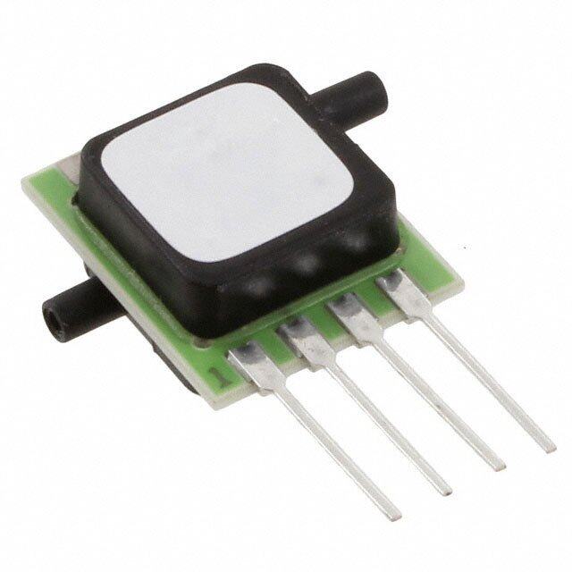
HSCMRRD006MD2A3产品简介:
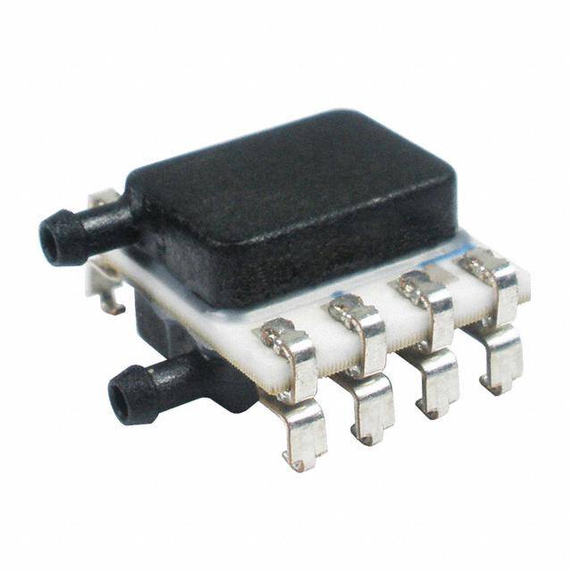
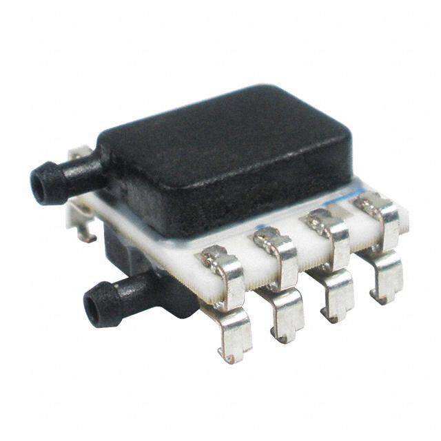
ICGOO电子元器件商城为您提供HSCMRRD006MD2A3由Honeywell Solid State Electronics设计生产,在icgoo商城现货销售,并且可以通过原厂、代理商等渠道进行代购。 HSCMRRD006MD2A3价格参考。Honeywell Solid State ElectronicsHSCMRRD006MD2A3封装/规格:压力传感器,变送器, 差分 压力 传感器 ±0.09 PSI(±0.6 kPa) 公型 - 0.08"(1.93mm) 双管 12 b 8-SMD,J 引线,双端口,同侧。您可以下载HSCMRRD006MD2A3参考资料、Datasheet数据手册功能说明书,资料中有HSCMRRD006MD2A3 详细功能的应用电路图电压和使用方法及教程。
Honeywell Sensing and Productivity Solutions旗下的型号HSCMRRD006MD2A3是一种压力传感器/变送器,广泛应用于工业自动化与控制系统中。该产品适用于测量气体或液体的压力,并将压力信号转换为标准的电信号输出,便于监测与控制。

其主要应用场景包括:

1. 工业设备:如空压机、液压系统、气动系统等,用于实时监控系统压力,保障设备安全运行;
2. 暖通空调(HVAC)系统:用于检测风压、水压,实现对风机、水泵等设备的智能控制;
3. 过程控制系统:在化工、制药、食品加工等行业中,用于精确控制生产流程中的压力参数;
4. 医疗设备:如呼吸机、麻醉机等需要高精度压力监测的设备中;
5. 测试与测量设备:用于实验室或现场的压力校准与数据采集系统。

该传感器具备高精度、稳定性强、耐腐蚀等特点,适合在较为复杂的工业环境中使用。
| 参数 | 数值 |
| 产品目录 | |
| 描述 | SENSOR PRES 6PSI DIFF 3.3V SMT板机接口压力传感器 SMT Radial Differential 3.3V |
| 产品分类 | |
| 品牌 | Honeywell |
| 产品手册 | http://sensing.honeywell.com/index.php?ci_id=151133 |
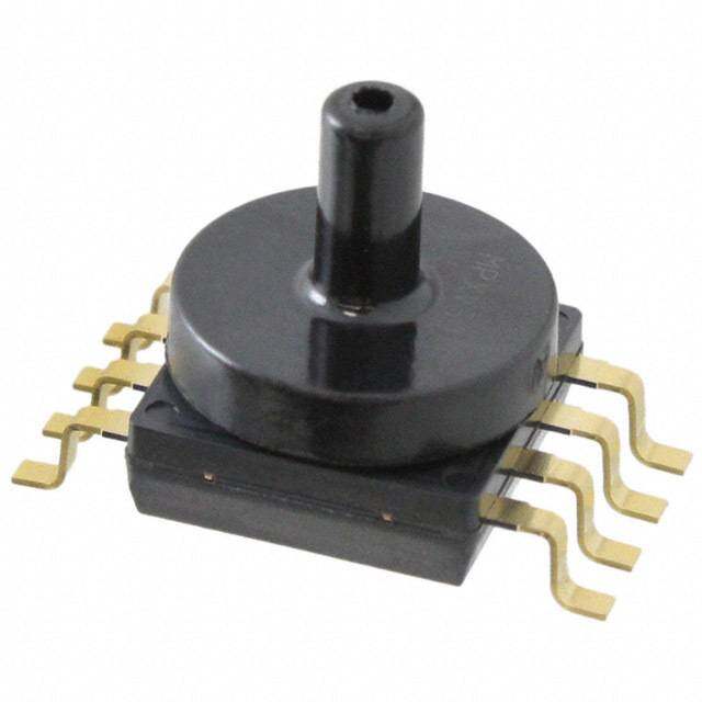
| 产品图片 |
|
| 产品系列 | 板机接口压力传感器,Honeywell HSCMRRD006MD2A3TruStability™ HSC |
| 数据手册 | 点击此处下载产品Datasheet点击此处下载产品Datasheet点击此处下载产品Datasheet点击此处下载产品Datasheet |
| 产品型号 | HSCMRRD006MD2A3 |
| rohs | 无铅 / 符合限制有害物质指令(RoHS)规范要求 |
| 产品种类 | 板机接口压力传感器 |
| 准确性 | 0.25 % |
| 出厂设置 | * |
| 压力类型 | Differential |
| 商标 | Honeywell |
| 安装风格 | SMD/SMT |
| 封装/外壳 | 8-SMD 模块 |
| 工作压力 | +/- 6 mbar |
| 工作温度 | -20°C ~ 85°C |
| 工作电源电压 | 3.3 V |
| 应用说明 | |
| 数字输出-总线接口 | I2C, SPI |
| 最大工作温度 | + 85 C |
| 最小工作温度 | - 20 C |
| 标准包装 | 1 |
| 电压-电源 | 3.3V |
| 电源电压-最大 | 5.25 V |
| 电源电压-最小 | 3 V |
| 电源电流 | 2.1 mA |
| 端口尺寸 | 公型,0.076"(1.93mm)双管 |
| 端口类型 | Dual Radial Barbed |
| 端子类型 | 表面贴装型 |
| 精度 | ±0.25%FSS |
| 系列 | HSC |
| 输出 | I²C, 0 x 28 |
| 输出类型 | Digital |


- 商务部:美国ITC正式对集成电路等产品启动337调查
- 曝三星4nm工艺存在良率问题 高通将骁龙8 Gen1或转产台积电
- 太阳诱电将投资9.5亿元在常州建新厂生产MLCC 预计2023年完工
- 英特尔发布欧洲新工厂建设计划 深化IDM 2.0 战略
- 台积电先进制程称霸业界 有大客户加持明年业绩稳了
- 达到5530亿美元!SIA预计今年全球半导体销售额将创下新高
- 英特尔拟将自动驾驶子公司Mobileye上市 估值或超500亿美元
- 三星加码芯片和SET,合并消费电子和移动部门,撤换高东真等 CEO
- 三星电子宣布重大人事变动 还合并消费电子和移动部门
- 海关总署:前11个月进口集成电路产品价值2.52万亿元 增长14.8%

PDF Datasheet 数据手册内容提取
TruStability® Board Mount Pressure Sensors HSC Series—High Accuracy, Compensated/Amplified ±1.6 mbar to ±10 bar | ±160 Pa to ±1 MPa | ±0.5 inH O to ±150 psi 2 Digital or Analog Output Datasheet
TruStability® Board Mount Pressure Sensors The TruStability® High Accuracy Silicon Ceramic (HSC) Series is a piezoresistive silicon pressure sensor offering a ratiometric analog or digital output for reading pressure over the specified full scale pressure span and temperature range. The HSC Series is fully calibrated and temperature compensated for sensor offset, sensitivity, temperature effects, and non- linearity using an on-board Application Specific Integrated Circuit (ASIC). Calibrated output values for pressure are updated at approximately 1 kHz for analog and 2 kHz for digital. The HSC Series is calibrated over the temperature range of 0 °C to 50 °C [32 °F to 122 °F]. The sensor is characterized for operation from a single power supply of either 3.3 Vdc or 5.0 Vdc. These sensors measure absolute, gage, or differential pressures. The absolute versions have an internal vacuum reference and an output value proportional to absolute pressure. Gage versions are referenced to atmospheric pressure and provide an output proportional to pressure variations from atmosphere. Differential versions allow measurement of pressure between the two pressure ports. The TruStability® pressure sensors are intended for use with non-corrosive, non-ionic gases, such as air and other dry gases. Available options extend the performance of these sensors to non-corrosive, non-ionic liquids for pressure ranges above 40 mbar | 4 kPa | 20 inH O. 2 All products are designed and manufactured according to ISO 9001 standards. , What makes our sensors better? Table of Contents • Stability and reliability Features and Benefits .................. 3-5 • Industry-leading accuracy of ±0.25 %FSS BFSL Potential Applications ....................6 General Specifications ................. 7-8 • Port and housing options simplify integration Analog Operating Specifications ...........9 • Wide pressure range, from ±1.6 mbar to ±10 bar | ±160 Pa to ±1 MPa | ±0.5 inH O to ±150 psi Digital Operating Specifications ...........10 2 • Small package size Transfer Function Limits .................11 • Extremely low power consumption Total Error Band Values .................12 Nomenclature and Order Guide ...........13 Pressure Range Specifications ±1.6 mbar to ±10 bar ..................14 ±160 Pa to ±1 MPa ....................15 ±0.5 inHO to ±150 psi .................16 2 Available Standard Configurations .......17-18 Dimensional Drawings DIP Packages ..................... 19-21 SMT Packages ................... 21-24 SIP Packages ..................... 24-29 Pinouts, PCB Layouts ...................30 TruStability® Board Mount Pressure Sensors Portfolio Overview .....................31 Additional Information. . . . . . . . . . . . . . . . . . .32 stability • accuracy • flexibility • small size 2 sensing.honeywell.com
Features ProPrietAry Honeywell teCHnology Combines high sensitivity with high overpressure and burst pressure while and Benefits providing industry leading stability—performance factors that are difficult to achieve in the same product; this gives the customer more flexibility in sensor implementation and reduces the customer design requirements for protecting the sensor without sacrificing the ability to sense very small changes in pressure. ProteCteD By MUltiPle gloBAl PAtentS inDUStry-leADing long-terM StABility Even after long-term use and thermal extremes, the sensor’s stability remains best in class: • Minimizes system calibration needs. • Improves system performance. • Helps support system uptime by minimizing the need to service or replace the sensor during its application life. totAl error BAnD (teB) Honeywell specifies TEB—the most comprehensive, clear, and meaningful measurement—that provides the sensor’s true performance over a compensated range of 0 °C to 50 °C [32 °F to 122 °F] (see Figure 1): • Minimizes individually testing and calibrating every sensor, decreasing manufacturing time and process costs. • Improves system accuracy. • Provides enhanced sensor interchangeability—there is minimal part-to-part variation in accuracy. All Possible Errors Offset +++ Full Scale Span ++ Pressure Non-Linearity ++ Pressure Hysteresis = Accuracy Total +++ = Error Band Pressure Non-Repeatability +++ Thermal Effect on Offset +++ Thermal Effect on Span +++ Thermal Hysteresis Figure 1. TEB Components for TruStability® Board Mount Pressure Sensors sensing.honeywell.com 3
Features inDUStry-leADing ACCUrACy and Benefits Extremely tight accuracy of ±0.25 %FSS BFSL (Full Scale Span Best Fit Straight Line) reduces software needed to correct system inaccuracies, minimizing system design time: • Avoids additional customer calibration. • Helps to improve system efficiency. • Often simplifies software development. HigH BUrSt PreSSUreS • Promotes system reliability and reduces potential system downtime. • Can simplify the design process. HigH working PreSSUre rAngeS Allows ultra-low pressure sensors to be used continuously well above the calibrated pressure range. inDUStry-leADing flexiBility Modular, flexible design with many package styles (with the same industry- leading stability), pressure ports, and options simplify integration into the device manufacturer’s application. wiDe vAriety of PreSSUre rAngeS From ±1.6 mbar to ±10 bar | ±160 Pa to ±1 MPa | ±0.5 inH O to 150 psi provide 2 support for many unique applications. MeetS iPC/JeDeC J-StD-020D.1 MoiStUre SenSitivity level 1 reqUireMentS • Allows the customer to avoid the thermal and mechanical damage during solder reflow attachment and/or repair that lesser rated products would incur. • Allows unlimited floor life when stored as specified (<30 ºC/85 %RH), simplifying storage and reducing scrap. • Never requires lengthy bakes prior to reflow. • Stable and usable shortly after reflow process allows for lean manufacturing. oPtionAl internAl DiAgnoStiC fUnCtionS • May reduce the need for redundant sensors in the system. • Detects most internal failures including burst sensors. energy effiCient Extremely low power consumption (less than 10 mW, typ.): • Reduces system power requirements. • Enables extended battery life. • Optional sleep mode available upon special request. 4 sensing.honeywell.com
Features oUtPUt: rAtioMetriC AnAlog; i2C- or SPi-CoMPAtiBle 14-Bit DigitAl oUtPUt (Min. 12-Bit SenSor reSolUtion) and Benefits Accelerates performance through reduced conversion requirements and the convenience of direct interface to microprocessors. SMAll Size Miniature 10 mm x 10 mm [0.39 in x 0.39 in] package is very small when compared to many board mount pressure sensors: • Occupies less area on the PCB. • Typically allows for easy placement on crowded PCBs or in small devices. reACH AnD roHS CoMPliAnt liqUiD MeDiA oPtion • Provides robustness in environments with condensing humidity. • Compatible with a variety of non-ionic fluids. • Available for pressure ranges above 40 mbar | 4 kPa | 20 inH 0. 2 sensing.honeywell.com 5
Potential Applications MeDiCAl • Airflow MonitorS • AneStHeSiA MACHineS • BlooD AnAlySiS MACHineS • gAS CHroMAtogrAPHy • gAS flow inStrUMentAtion • kiDney DiAlySiS MACHineS • oxygen ConCentrAtorS • PneUMAtiC ControlS • reSPirAtory MACHineS • SleeP APneA eqUiPMent • ventilAtorS • SPiroMeterS • neBUlizerS • HoSPitAl rooM Air PreSSUre inDUStriAl • BAroMetry • flow CAliBrAtorS • gAS CHroMAtogrAPHy • gAS flow inStrUMentAtion • HvAC • life SCienCeS • PneUMAtiC Control • vAv (vAriABle Air volUMe) Control • CloggeD HvAC filter DeteCtion • HvAC trAnSMitterS • inDoor Air qUAlity 6 sensing.honeywell.com
General Specifications table 1. Absolute Maximum ratings1 Characteristic Min. Max. Unit Supply voltage (V ) -0.3 6.0 Vdc supply Voltage on any pin -0.3 V + 0.3 V supply Digital interface clock frequency: I2C 100 400 kHz SPI 50 800 ESD susceptibility (human body model) 3 — kV Storage temperature -40 [-40] 85 [185] °C [°F] Soldering time and temperature: lead solder temperature (SIP, DIP) 4 s max. at 250 °C [482 °F] peak reflow temperature (SMT) 15 s max. at 250 °C [482 °F] 1Absolute maximum ratings are the extreme limits the device will withstand without damage. table 2. environmental Specifications Characteristic Parameter Humidity: gases only (See “Options N and D” in Figure 4.) 0% to 95% RH, non-condensing liquid media (See “Options T and V” in Figure 4.) 100% condensing or direct liquid media on Port 1 Vibration MIL-STD-202G, Method 204D, Condition B (15 g, 10 Hz to 2 Hz) Shock MIL-STD-202G, Method 213B, Condition C (100 g, 6 ms duration) Life1 1 million pressure cycles minimum J-STD-020-D.1 Moisture Sensitivity Level 1 Solder reflow (unlimited shelf life when stored at <30 °C/85 % RH) 1Life may vary depending on specific application in which the sensor is utilized. sensing.honeywell.com 7
General Specifications table 3. wetted Materials1 Component Port 1 (Pressure Port) Port 2 (reference Port) Ports and covers high temperature polyamide high temperature polyamide Substrate alumina ceramic alumina ceramic Adhesives epoxy, silicone epoxy, silicone Electronic components ceramic, silicon, glass, solder silicon, glass, gold 1Contact Honeywell Customer Service for detailed material information. CAUTION PRODUCT DAMAGE FOR SENSORS WITH LIQUID MEDIA OPTION (ONLY AVAILABLE 60 MBAR | 6 KPA | 1 PSI AND ABOVE) • Ensure liquid media is applied to Port 1 only; Port 2 is not compatible with liquids. • Ensure liquid media contains no particulates. All TruStability® sensors are dead-ended devices. Particulates can accumulate inside the sensor, causing damage or affecting sensor output. • Recommend that the sensor be positioned with Port 1 facing downwards; any particulates in the system are less likely to enter and settle within the pressure sensor if it is in this position. • Ensure liquid media does not create a residue when dried; build-up inside the sensor may affect sensor output. Rinsing of a dead-ended sensor is difficult and has limited effectiveness for removing residue. • Ensure liquid media are compatible with wetted materials. Non-compatible liquid media will degrade sensor performance and may lead to sensor failure. Failure to comply with these instructions may result in product damage. table 4. Sensor Pressure types Pressure type Description Absolute Output is proportional to the difference between applied pressure and a built-in vacuum reference. Differential Output is proportional to the difference between the pressures applied to each port (Port 1 – Port 2). Gage Output is proportional to the difference between applied pressure and atmospheric (ambient) pressure. 8 sensing.honeywell.com
Analog Operating Specifications table 5. Analog operating Specifications Characteristic Min. typ. Max. Unit Supply voltage (V ):1, 2, 3 supply pressure ranges >60 mbar | 6 kPa | 1 psi: 3.3 Vdc 3.0 3.3 3.6 5.0 Vdc 4.75 5.0 5.25 Vdc pressure ranges <40 mbar | 4 kPa | 20 inHO: 2 3.3 Vdc 3.27 3.3 3.33 5.0 Vdc 4.95 5.0 5.05 Supply current: 3.3 Vdc — 2.1 2.8 mA 5.0 Vdc — 2.7 3.5 Operating temperature range4 -20 [-4] — 85 [185] °C [°F] Compensated temperature range5 0 [-32] — 50 [122] °C [°F] Startup time (power up to data ready) — — 5 ms Response time — 1 — ms Clipping limit: upper — — 97.5 %Vsupply lower 2.5 — — Accuracy6 — — ±0.25 %FSS BFSL8 Output resolution 0.03 — — %FSS Orientation sensitivity (±1 g):7, 9 pressure ranges <40 mbar | 4 kPa | 20 inHO — ±0.1 — %FSS8 2 pressure ranges <2.5 mbar | 250 Pa | 1 inHO — ±0.2 — 2 1Sensors are either 3.3 Vdc or 5.0 Vdc based on the catalog listing selected. 2Ratiometricity of the sensor (the ability of the device output to scale to the supply voltage) is achieved within the specified operating voltage. 3The sensor is not reverse polarity protected. Incorrect application of supply voltage or ground to the wrong pin may cause electrical failure. 4Operating temperature range: The temperature range over which the sensor will produce an output proportional to pressure. 5Compensated temperature range: The temperature range over which the sensor will produce an output proportional to pressure within the specified performance limits. 6Accuracy: The maximum deviation in output from a Best Fit Straight Line (BFSL) fitted to the output measured over the pressure range at 25 °C [77 °F]. Includes all errors due to pressure non-linearity, pressure hysteresis, and non-repeatability. 7Orientation sensitivity: The maximum change in offset of the sensor due to a change in position or orientation relative to Earth’s gravitational field. 8Full Scale Span (FSS): The algebraic difference between the output signal measured at the maximum (Pmax.) and minimum (Pmin.) limits of the pressure range. (See Figure 4 for ranges.) 9Insignificant for pressure ranges above 40 mbar | 4 kPa | 20 inHO. 2 sensing.honeywell.com 9
Digital Operating Specifications table 6. Digital operating Specifications Characteristic Min. typ. Max. Unit Supply voltage (V ):1, 2, 3 supply pressure ranges >60 mbar | 6 kPa | 1 psi: 3.3 Vdc 3.0 3.3 3.6 5.0 Vdc 4.75 5.0 5.25 Vdc pressure ranges <40 mbar | 4 kPa | 20 inHO: 2 3.3 Vdc 3.27 3.3 3.33 5.0 Vdc 4.95 5.0 5.05 Supply current: 3.3 Vdc — 3.1 3.9 mA 5.0 Vdc — 3.7 4.6 Operating temperature range4 -20 [-4] — 85 [185] °C [°F] Compensated temperature range5 0 [-32] — 50 [122] °C [°F] Startup time (power up to data ready) — — 3 ms Response time — 0.46 — ms SPI/I2C voltage level: low — — 20 %Vsupply high 80 — — Pull up on SDA/MISO, SCL/SCLK, SS 1 — — kOhm Accuracy6 — — ±0.25 %FSS BFSL8 Output resolution 12 — — bits Orientation sensitivity (±1 g):7, 9 pressure ranges <40 mbar | 4 kPa | 20 inHO — ±0.1 — %FSS8 2 pressure ranges <2.5 mbar | 250 Pa | 1 inHO — ±0.2 — 2 1Sensors are either 3.3 Vdc or 5.0 Vdc based on the catalog listing selected. 2Ratiometricity of the sensor (the ability of the device output to scale to the supply voltage) is achieved within the specified operating voltage. 3The sensor is not reverse polarity protected. Incorrect application of supply voltage or ground to the wrong pin may cause electrical failure. 4Operating temperature range: The temperature range over which the sensor will produce an output proportional to pressure. 5Compensated temperature range: The temperature range over which the sensor will produce an output proportional to pressure within the specified performance limits. 6Accuracy: The maximum deviation in output from a Best Fit Straight Line (BFSL) fitted to the output measured over the pressure range at 25 °C [77 °F]. Includes all errors due to pressure non-linearity, pressure hysteresis, and non-repeatability. 7Orientation sensitivity: The maximum change in offset of the sensor due to a change in position or orientation relative to Earth’s gravitational field. 8Full Scale Span (FSS): The algebraic difference between the output signal measured at the maximum (Pmax.) and minimum (Pmin.) limits of the pressure range. (See Figure 4 for ranges.) 9Insignificant for pressure ranges above 40 mbar | 4 kPa | 20 inHO. 2 table 7. Sensor output at Significant Percentages (Digital versions only) % output Digital Counts (decimal) Digital Counts (hex) 0 0 0x0000 10 1638 0x0666 50 8192 0x2000 90 14746 0x399A 100 16383 0x3FFF 10 sensing.honeywell.com
Transfer Function Limits figure 2. transfer function limits1 Analog versions Compensated Pressure Range 100 90 ) y l 80 p p 70 u s 60 Ideal V % 50 1% Total Error Band ( 40 t u p 30 t u 20 O 10 0 0 1 2 3 4 5 6 7 8 9 10 P P min. max. Pressure (example unit) 0.8 x Vsupply Output (V) = x (Pressure – P ) + 0.10 x Vsupply applied min. P – P max. min. Digital versions Compensated Pressure Range 100 ) s t 90 n u 80 o c 70 4 1 60 Ideal 2 f 50 o 1% Total Error Band % 40 ( 30 t u 20 p ut 10 O 0 0 1 2 3 4 5 6 7 8 9 10 P P min. max. Pressure (example unit) 80% Output (% of 214 counts) = x (Pressure – P ) + 10% applied min. P – P max. min. 1Transfer Function “A” is shown. See Figure 4 for other available transfer function options. sensing.honeywell.com 11
550 inH20 500 inH20 18x 1000 mbar 50x 250x Pressure11x 16x 30x CalibrB(amutirensditm PPurmrees)ssusruere Range 159x Overpressure (maximum) Working Pressure Range 5x 15x CPraelisbsruarteed R ange (x) 84x Total Error Band Values 30 inH20 10 inH20 4 mbar figure 3. total error Band values for full Scale Span Pressure ranges Differential Gage 150 psi 10 bar | 1 MPa 150 psi 10 bar | 1 MPa Low to Mid Low to Mid Pressure Pressure 1 psi 1 psi 60 mbar | 6 kPa 60 mbar | 6 kPa 20 inHO 20 inHO 2 2 Ultra-Low Ultra-Low Pressure 40 mbar | 4 kPa Pressure 40 mbar | 4 kPa 10 inHO 25 mbar | 2.5 kPa 10 inHO 25 mbar | 2.5 kPa 2 2 16 mbar | 1.6 kPa 16 mbar | 1.6 kPa 5 inHO 5 inHO 2 2 10 mbar | 1 kPa 10 mbar | 1 kPa 6 mbar | 600 Pa 2 inHO 2 inHO 2 4 mbar | 400 Pa 2 2.5 mbar | 250 Pa 2.5 mbar | 250 Pa 0 inHO 1.6 mbar | 160 Pa 0 mbar | 0 Pa 0 inHO 0 mbar | 0 Pa 2 0% 2 0% ±1 Ideal ±1 ±1.5 Accuracy (%FSS) ±1.5 ±2 ±2 Total Error Band (%FSS) ±2.5 ±3 12 sensing.honeywell.com
Nomenclature and Order Guide figure 4. nomenclature and order guide For example, HSCDNNN150PGAA3 defines an HSC Series TruStability® Pressure Sensor, DIP package, NN pressure port, no special options,150 psi gage pressure range, analog output type, 10% to 90% of Vsupply transfer function, 3.3 Vdc supply voltage. H S C D N N N 1 5 0 P G A A 3 Supply Voltage Product Series 3 3.3 Vdc HSC High Accuracy, Compensated/Amplified 5 5.0 Vdc Transfer Function1 Package A 10% to 90% of Vsupply (analog), 214 counts (digital) D DIP (Dual Inline Pin) B 5% to 95% of Vsupply (analog), 214 counts (digital) M SMT (Surface Mount Technology) C 5% to 85% of Vsupply (analog), 214 counts (digital) S SIP (Single Inline Pin) F 4% to 94% of Vsupply (analog), 214 counts (digital) Pressure Port Output Type2 DIP SMT SIP A Analog 4 I2C, Address 0x48 NN No ports NN No ports NNNo ports S2 IS2CP,I Address 0x28 56 II22CC,, AAddddrreessss 00xx5688 Dual axial Pressure Range3, 4 3 I2C, Address 0x38 7 I2C, Address 0x78 AA barbed ports, opposite sides ±1.6 mbar to ±10 bar ±160 Pa to ±1 MPa ±0.5 inH2O to ±150 psi Absolute Absolute Absolute AN Sbainrgbleed a pxoiartl ANSbainrgbleed a pxoiartl ANSbainrgbleed a pxoiartl 010.61BBAA 00 bbaarr ttoo 11. 6b abrar 110600KKAA 00 kkPPaa ttoo 110600 kkPPaa 001350PPAA00 ppssii ttoo 1350 ppssii 2.5BA 0 bar to 2.5 bar 250KA 0 kPa to 250 kPa 060PA0 psi to 60 psi LN Sbainrgbllees asx piaol rt LN Sbainrgbllees asx piaol rt LN Sbainrgbllees asx piaol rt 004BA 0 bar to 4 bar 400KA 0 kPa to 400 kPa 100PA0 psi to 100 psi 006BA 0 bar to 6 bar 600KA 0 kPa to 600 kPa 150PA0 psi to 150 psi FF Fmaxaoisautlen bnt,ae drrbueadl 010BA 0 bar to 10 bar 001GA 0 kPa to 1 MPa psiodretss, opposite Differential Differential Differential Fastener 1.6MD ±1.6 mbar 160LD ±160 Pa 0.5ND ±0.5 inH2O FN maxoiauln bt,a srbinegdle 2.5MD ±2.5 mbar 250LD ±250 Pa 001ND ±1 inH2O port 004MD ±4 mbar 400LD ±400 Pa 002ND±2 inH2O GNRfaisbtebneedr mount, 006MD ±6 mbar 600LD ±600 Pa 004ND ±4 inH2O sbianrgbleed a pxioa0rlt08B 010MD ±10 mbar 001KD ±1 kPa 005ND ±5 inH2O 016MD ±16 mbar 1.6KD ±1.6 kPa 010ND±10 inH2O NB Fmaosutennt,e drual 025MD ±25 mbar 2.5KD ±2.5 kPa 020ND ±20 inH2O asaximale p soidrtes, 040MD ±40 mbar 004KD ±4 kPa 030ND ±30 inH2O 060MD ±60 mbar 006KD ±6 kPa 001PD ±1 psi RNSingle radial RN Single radial RNSingle radial 100MD ±100 mbar 010KD ±10 kPa 005PD ±5 psi barbed port barbed port barbed port 160MD ±160 mbar 016KD ±16 kPa 015PD ±15 psi Dual radial Dual radial Dual radial 250MD ±250 mbar 025KD ±25 kPa 030PD ±30 psi RR bsaamrbee ds ipdoerts, RR bsaamrbee ds ipdoerts, RR bsaamrbee ds ipdoerts, 400MD ±400 mbar 040KD ±40 kPa 060PD ±60 psi 600MD ±600 mbar 060KD ±60 kPa Dual radial Dual radial Dual radial 001BD ±1 bar 100KD ±100 kPa DR barbed ports, DR barbed ports, DR barbed ports, opposite sides opposite sides opposite sides 1.6BD ±1.6 bar 160KD ±160 kPa 2.5BD ±2.5 bar 250KD ±250 kPa JN Sbainrgbllees rsa dpioarlt JN Sbainrgbllees rsa dpioarlt JN Sbainrgbllees rsa dpioarlt 004BD ±4 bar 400KD ±400 kPa Gage Gage Gage JJ Dbsaaumrablel er assdisd iaeplorts, JJ Dbsaaumrablel er assdisd iaeplorts, JJ Dbsaaumrablel er assdisd iaeplorts, 20.054MMGG 00 mmbbaarr ttoo 24. 5m bmabrar 245000LLGG 00 PPaa ttoo 245000 PPaa 000012NNGG00 iinnHH22OO ttoo 12 iinnHH22OO HHFmraaodsuitaenln tb,e adrrubaeld 000160MMGG 00 mmbbaarr ttoo 610 m mbbaarr 600001LKGG 00 PkPaa t oto 6 10 0k PPaa 000045NNGG00 iinnHH22OO ttoo 45 iinnHH22OO psiodrets, same 016MG 0 mbar to 16 mbar 1.6KG 0 kPa to 1.6 kPa 010NG 0 inH2O to 10 inH2O Fastener 025MG 0 mbar to 25 mbar 2.5KG 0 kPa to 2.5 kPa 020NG0 inH2O to 20 inH2O HNmraoduianl tb, asirnbgelde 040MG 0 mbar to 40 mbar 004KG 0 kPa to 4 kPa 030NG0 inH2O to 30 inH2O port 060MG 0 mbar to 60 mbar 006KG 0 kPa to 6 kPa 001PG 0 psi to 1 psi 100MG 0 mbar to 100 mbar 010KG 0 kPa to 10 kPa 005PG0 psi to 5 psi Manifold MNmount, outer 160MG 0 mbar to 160 mbar 016KG 0 kPa to 16 kPa 015PG0 psi to 15 psi diameter seal 250MG 0 mbar to 250 mbar 025KG 0 kPa to 25 kPa 030PG 0 psi to 30 psi Manifold 400MG 0 bar to 400 mbar 040KG 0 kPa to 40 kPa 060PG 0 psi to 60 psi SN mount, inner diameter seal 600MG 0 bar to 600 mbar 060KG 0 kPa to 60 kPa 100PG 0 psi to 100 psi 001BG 0 bar to 1 bar 100KG 0 kPa to 100 kPa 150PG 0 psi to 150 psi Options5, 6 1.6BG 0 bar to 1.6 bar 160KG 0 kPa to 160 kPa 2.5BG 0 bar to 2.5 bar 250KG 0 kPa to 250 kPa N Dry gases only, no diagnostics 004BG 0 bar to 4 bar 400KG 0 kPa to 400 kPa D Dry gases only, diagnostics on 006BG 0 bar to 6 bar 600KG 0 kPa to 600 kPa T Liquid media on Port 1, no diagnostics 010BG 0 bar to 10 bar 001GG 0 kPa to 1 MPa V Liquid media on Port 1, diagnostics on 1The transfer function limits define the output of the sensor at a given pressure input. By specifying Pmin. and Pmax., the output at Pmin. and Pmax., the complete transfer function of the 1The trans f esre fnusnocrt ioisn d liemfiintse dd.e Sfineee tthhee ogurtappuhti coaf lt hreep sreensseonrt aatti oan gsi voefn t hpere tsrasnusrefe irn pfuunt.c Btioyn s pine tchifey ipnrgo Pdumcitn .d aantads Phemeat,x .F, itghuer eo u2t.p Fuot ra ot tPhmerin a. vaanilda bPlme atrxa.n, sthfeer c foumncptiloentes t craonnstfaecrt fHunocnteioynw oefl lt hCeu ssetonmsoerr iSs edrevfiicnee.d . See the graph2SicPaIl roeuptrpeuste fnutnactitoionns iosf nthoet atrvaanislafebrl efu innc StiIoPn pina cFkigaugree. 2. For other available transfer functions contact Honeywell Customer Service. 2SPI outpu3Ct fuusntcotmio np rise snsout raev arailanbglees i na rSeI Pa vpaaiclakbalgee. .Contact Honeywell Customer Service for more information. 3Custom p4Sreeses uthree reaxnpgleasn aatrieo nav oafi lasebnles. oCr opnrteascstu Hreo ntyepyewse ilnl C thuest opmroedru Scte drvaictaes fhoer emt,o Traeb inlefo 4rm. ation. 5See the CAUTION in this document. 4See the explanation of sensor pressure types in Table 4. 6Options T and V are only available on pressure ranges ±60 mbar to ±10 bar | ±6 kPa to ±1 MPa | ±1 psi to ±150 psi. 5See the CAUTION in this document. 6Options T and V are only available on pressure ranges ±60 mbar to ±10 bar | ±6 kPa to ±1 MPa | ±1 psi to ±150 psi. sensing.honeywell.com 13
Pressure Range Specifications ±1.6 mbar to ±10 bar table 8. Pressure range Specifications for ±1.6 mbar to ±10 bar Pressure Pressure total error long-term range Common total error range working over Burst Band after Stability (see n. x. Unit Pressure1 Pressure2 Pressure3 Mode Band5 Auto-zero6 1000 hr, 25 °C figure 4) mi ma Pressure4 (%fSS) (%fSS) (%fSS) P P Absolute 001BA 0 1 bar - 2 4 - ±1% - ±0.25% 1.6BA 0 1.6 bar - 4 8 - ±1% - ±0.25% 2.5BA 0 2.5 bar - 6 8 - ±1% - ±0.25% 004BA 0 4 bar - 8 16 - ±1% - ±0.25% 006BA 0 6 bar - 17 17 - ±1% - ±0.25% 010BA 0 10 bar - 17 17 - ±1% - ±0.25% Differential 1.6MD -1.6 1.6 mbar 335 675 1000 3450 ±2.5% ±1.75% ±0.5% 2.5MD -2.5 2.5 mbar 335 675 1000 3450 ±2% ±1.25% ±0.35% 004MD -4 4 mbar 335 675 1000 3450 ±1.5% ±0.75% ±0.35% 006MD -6 6 mbar 335 675 1000 3450 ±1% ±0.75% ±0.35% 010MD -10 10 mbar 375 750 1250 5450 ±1% ±0.5% ±0.25% 016MD -16 16 mbar 375 750 1250 5450 ±1% ±0.5% ±0.25% 025MD -25 25 mbar 435 850 1350 10450 ±1% ±0.5% ±0.25% 040MD -40 40 mbar 435 850 1350 10450 ±1% ±0.5% ±0.25% 060MD -60 60 mbar - 850 1000 10000 ±1% - ±0.25% 100MD -100 100 mbar - 1400 2500 10000 ±1% - ±0.25% 160MD -160 160 mbar - 1400 2500 10000 ±1% - ±0.25% 250MD -250 250 mbar - 1400 2500 10000 ±1% - ±0.25% 400MD -400 400 mbar - 2000 4000 10000 ±1% - ±0.25% 600MD -600 600 mbar - 2000 4000 10000 ±1% - ±0.25% 001BD -1 1 bar - 4 8 10 ±1% - ±0.25% 1.6BD -1.6 1.6 bar - 8 16 10 ±1% - ±0.25% 2.5BD -2.5 2.5 bar - 8 16 10 ±1% - ±0.25% 004BD -4.0 4.0 bar - 16 17 10 ±1% - ±0.25% gage 2.5MG 0 2.5 mbar 335 675 1000 3450 ±3% ±2% ±0.5% 004MG 0 4 mbar 335 675 1000 3450 ±2% ±1.25% ±0.5% 006MG 0 6 mbar 335 675 1000 3450 ±2% ±1% ±0.35% 010MG 0 10 mbar 335 675 1000 3450 ±1.5% ±0.75% ±0.35% 016MG 0 16 mbar 335 675 1000 3450 ±1% ±0.75% ±0.25% 025MG 0 25 mbar 375 750 1250 5450 ±1% ±0.5% ±0.25% 040MG 0 40 mbar 375 750 1250 5450 ±1% ±0.5% ±0.25% 060MG 0 60 mbar - 850 1000 5450 ±1% ±0.5% ±0.25% 100MG 0 100 mbar - 850 1000 10000 ±1% - ±0.25% 160MG 0 160 mbar - 850 1000 10000 ±1% - ±0.25% 250MG 0 250 mbar - 1400 2500 10000 ±1% - ±0.25% 400MG 0 400 mbar - 2000 4000 10000 ±1% - ±0.25% 600MG 0 600 mbar - 2000 4000 10000 ±1% - ±0.25% 001BG 0 1 bar - 2 4 10 ±1% - ±0.25% 1.6BG 0 1.6 bar - 4 8 10 ±1% - ±0.25% 2.5BG 0 2.5 bar - 8 16 10 ±1% - ±0.25% 004BG 0 4 bar - 8 16 16 ±1% - ±0.25% 006BG 0 6 bar - 17 17 17 ±1% - ±0.25% 010BG 0 10 bar - 17 17 17 ±1% - ±0.25% 1Working pressure: The maximum pressure that may be applied to any port of the sensor in continuous use. This pressure may be outside the operating pressure range limits (Pmin. to Pmax.) in which case the sensor may not provide a valid output until presssure is returned to within the operating pressure range. Tested to 1 million cycles, minimum. 2Overpressure: The maximum pressure which may safely be applied to the product for it to remain in specification once pressure is returned to the operating pressure range. Exposure to higher pressures may cause permanent damage to the product. Unless otherwise specified this applies to all available pressure ports at any temperature with the operating temperature range. 3Burst pressure: The maximum pressure that may be applied to any port of the product without causing escape of pressure media. Product should not be expected to function after exposure to any pressure beyond the burst pressure. 4Common mode pressure: The maximum pressure that can be applied simultaneously to both ports of a differential pressure sensor without causing changes in specified performance. 5Total Error Band: The maximum deviation from the ideal transfer function over the entire compensated temperature and pressure range. Includes all errors due to offset, full scale span, pressure non-linearity, pressure hysteresis, repeatability, thermal effect on offset, thermal effect on span, and thermal hysteresis (see Figure 1). 6Total Error Band after Auto-Zero: The maximum deviation from the ideal transfer function over the entire compensated pressure range at a constant temperature and supply voltage for a minimum of 24 hours after an auto-zero operation. Includes all errors due to full scale span, pressure non-linearity, pressure hysteresis, and thermal effect on span. 14 sensing.honeywell.com
Pressure Range Specifications ±160 Pa to ±1 MPa table 9. Pressure range Specifications for ±160 Pa to ±1 MPa Pressure Pressure total error long-term range Common total error range working over Burst Band after Stability (see n. x. Unit Pressure1 Pressure2 Pressure3 Mode Band5 Auto-zero6 1000 hr, 25 °C figure 4) mi ma Pressure4 (%fSS) (%fSS) (%fSS) P P Absolute 100KA 0 100 kPa - 200 400 - ±1% - ±0.25% 160KA 0 160 kPa - 400 800 - ±1% - ±0.25% 250KA 0 250 kPa - 600 800 - ±1% - ±0.25% 400KA 0 400 kPa - 800 1600 - ±1% - ±0.25% 600KA 0 600 kPa - 1700 1700 - ±1% - ±0.25% 001GA 0 1 MPa - 1700 1700 - ±1% - ±0.25% Differential 160LD -160 160 Pa 33500 67500 100000 345000 ±2.5% ±1.75% ±0.5% 250LD -250 250 Pa 33500 67500 100000 345000 ±2% ±1.25% ±0.35% 400LD -400 400 Pa 33500 67500 100000 345000 ±1.5% ±0.75% ±0.35% 600LD -600 600 Pa 33500 67500 100000 345000 ±1% ±0.75% ±0.35% 001KD -1 1 kPa 37.5 75 125 545 ±1% ±0.5% ±0.25% 1.6KD -1.6 1.6 kPa 37.5 75 125 545 ±1% ±0.5% ±0.25% 2.5KD -2.5 2.5 kPa 43.5 85 135 1045 ±1% ±0.5% ±0.25% 004KD -4 4 kPa 43.5 85 135 1045 ±1% ±0.5% ±0.25% 006KD -6 6 kPa - 85 100 1000 ±1% - ±0.25% 010KD -10 10 kPa - 140 250 1000 ±1% - ±0.25% 016KD -16 16 kPa - 140 250 1000 ±1% - ±0.25% 025KD -25 25 kPa - 140 250 1000 ±1% - ±0.25% 040KD -40 40 kPa - 200 400 1000 ±1% - ±0.25% 060KD -60 60 kPa - 200 400 1000 ±1% - ±0.25% 100KD -100 100 kPa - 400 800 1000 ±1% - ±0.25% 160KD -160 160 kPa - 800 1600 1000 ±1% - ±0.25% 250KD -250 250 kPa - 800 1600 1000 ±1% - ±0.25% 400KD -400 400 kPa - 1600 1700 1000 ±1% - ±0.25% gage 250LG 0 250 Pa 33500 67500 100000 345000 ±3% ±2% ±0.5% 400LG 0 400 Pa 33500 67500 100000 345000 ±2% ±1.25% ±0.5% 600LG 0 600 Pa 33500 67500 100000 345000 ±2% ±1% ±0.35% 001KG 0 1 kPa 33.5 67.5 100 345 ±1.5% ±0.75% ±0.35% 1.6KG 0 1.6 kPa 33.5 67.5 100 345 ±1% ±0.75% ±0.25% 2.5KG 0 2.5 kPa 37.5 75 125 545 ±1% ±0.5% ±0.25% 004KG 0 4 kPa 37.5 75 125 545 ±1% ±0.5% ±0.25% 006KG 0 6 kPa - 85 100 545 ±1% ±0.5% ±0.25% 010KG 0 10 kPa - 85 100 1000 ±1% - ±0.25% 016KG 0 16 kPa - 85 100 1000 ±1% - ±0.25% 025KG 0 25 kPa - 140 250 1000 ±1% - ±0.25% 040KG 0 40 kPa - 200 400 1000 ±1% - ±0.25% 060KG 0 60 kPa - 200 400 1000 ±1% - ±0.25% 100KG 0 100 kPa - 200 400 1000 ±1% - ±0.25% 160KG 0 160 kPa - 400 800 1000 ±1% - ±0.25% 250KG 0 250 kPa - 800 1600 1000 ±1% - ±0.25% 400KG 0 400 kPa - 800 1600 1600 ±1% - ±0.25% 600KG 0 600 kPa - 1700 1700 1700 ±1% - ±0.25% 001GG 0 1 MPa - 1.7 1.7 1.7 ±1% - ±0.25% 1Working pressure: The maximum pressure that may be applied to any port of the sensor in continuous use. This pressure may be outside the operating pressure range limits (Pmin. to Pmax.) in which case the sensor may not provide a valid output until presssure is returned to within the operating pressure range. Tested to 1 million cycles, minimum. 2Overpressure: The maximum pressure which may safely be applied to the product for it to remain in specification once pressure is returned to the operating pressure range. Exposure to higher pressures may cause permanent damage to the product. Unless otherwise specified this applies to all available pressure ports at any temperature with the operating temperature range. 3Burst pressure: The maximum pressure that may be applied to any port of the product without causing escape of pressure media. Product should not be expected to function after exposure to any pressure beyond the burst pressure. 4Common mode pressure: The maximum pressure that can be applied simultaneously to both ports of a differential pressure sensor without causing changes in specified performance. 5Total Error Band: The maximum deviation from the ideal transfer function over the entire compensated temperature and pressure range. Includes all errors due to offset, full scale span, pressure non-linearity, pressure hysteresis, repeatability, thermal effect on offset, thermal effect on span, and thermal hysteresis (see Figure 1). 6Total Error Band after Auto-Zero: The maximum deviation from the ideal transfer function over the entire compensated pressure range at a constant temperature and supply voltage for a minimum of 24 hours after an auto-zero operation. Includes all errors due to full scale span, pressure non-linearity, pressure hysteresis, and thermal effect on span. sensing.honeywell.com 15
Specifications ±0.5 inH O to ±150 psi 2 table 10. Pressure range Specifications for 0.5 inHo to 150 psi 2 Pressure Pressure Common total error long-term range total error range working over Burst Mode Band after Stability (see n. x. Unit Pressure1 Pressure2 Pressure3 Pressure4 Band5 Auto-zero6 1000 hr, 25 °C figure 4) mi ma (%fSS) (%fSS) (%fSS) P P Absolute 015PA 0 15 psi - 30 60 - ±1% - ±0.25% 030PA 0 30 psi - 60 120 - ±1% - ±0.25% 060PA 0 60 psi - 120 240 - ±1% - ±0.25% 100PA 0 100 psi - 250 250 - ±1% - ±0.25% 150PA 0 150 psi - 250 250 - ±1% - ±0.25% Differential 0.5ND -0.5 0.5 inHO 135 270 415 1400 ±3% ±2% ±0.5% 2 001ND -1 1 inHO 135 270 415 1400 ±2% ±1.25% ±0.35% 2 002ND -2 2 inHO 135 270 415 1400 ±1% ±0.75% ±0.35% 2 004ND -4 4 inHO 150 300 500 2200 ±1% ±0.5% ±0.25% 2 005ND -5 5 inHO 150 300 500 2200 ±1% ±0.5% ±0.25% 2 010ND -10 10 inHO 175 350 550 4200 ±1% ±0.5% ±0.25% 2 020ND -20 20 inHO 175 350 550 4200 ±1% ±0.5% ±0.25% 2 030ND -30 30 inHO 175 350 550 4200 ±1% ±0.5% ±0.25% 2 001PD -1 1 psi - 10 15 150 ±1% - ±0.25% 005PD -5 5 psi - 30 40 150 ±1% - ±0.25% 015PD -15 15 psi - 60 120 150 ±1% - ±0.25% 030PD -30 30 psi - 120 240 150 ±1% - ±0.25% 060PD -60 60 psi - 250 250 250 ±1% - ±0.25% gage 001NG 0 1 inHO 135 270 415 1400 ±3% ±2% ±0.5% 2 002NG 0 2 inHO 135 270 415 1400 ±2% ±1.25% ±0.35% 2 004NG 0 4 inHO 135 270 415 1400 ±1.5% ±0.75% ±0.35% 2 005NG 0 5 inHO 135 270 415 1400 ±1% ±0.75% ±0.25% 2 010NG 0 10 inHO 150 300 500 2200 ±1% ±0.5% ±0.25% 2 020NG 0 20 inHO 175 350 550 4200 ±1% ±0.5% ±0.25% 2 030NG 0 30 inHO 175 350 550 4200 ±1% ±0.5% ±0.25% 2 001PG 0 1 psi - 10 15 150 ±1% - ±0.25% 005PG 0 5 psi - 30 40 150 ±1% - ±0.25% 015PG 0 15 psi - 30 60 150 ±1% - ±0.25% 030PG 0 30 psi - 60 120 150 ±1% - ±0.25% 060PG 0 60 psi - 120 240 250 ±1% - ±0.25% 100PG 0 100 psi - 250 250 250 ±1% - ±0.25% 150PG 0 150 psi - 250 250 250 ±1% - ±0.25% 1Working pressure: The maximum pressure that may be applied to any port of the sensor in continuous use. This pressure may be outside the operating pressure range limits (Pmin. to Pmax.) in which case the sensor may not provide a valid output until pressure is returned to within the operating pressure range. Tested to 1 million cycles, minimum. 2Overpressure: The maximum pressure which may safely be applied to the product for it to remain in specification once pressure is returned to the operating pressure range. Exposure to higher pressures may cause permanent damage to the product. Unless otherwise specified this applies to all available pressure ports at any temperature with the operating temperature range. 3Burst pressure: The maximum pressure that may be applied to any port of the product without causing escape of pressure media. Product should not be expected to function after exposure to any pressure beyond the burst pressure. 4Common mode pressure: The maximum pressure that can be applied simultaneously to both ports of a differential pressure sensor without causing changes in specified performance. 5Total Error Band: The maximum deviation from the ideal transfer function over the entire compensated temperature and pressure range. Includes all errors due to offset, full scale span, pressure non-linearity, pressure hysteresis, repeatability, thermal effect on offset, thermal effect on span, and thermal hysteresis 6Total Error Band after Auto-Zero: The maximum deviation from the ideal transfer function over the entire compensated pressure range at a constant temperature and supply voltage for a minimum of 24 hours after an auto-zero operation. Includes all errors due to full scale span, pressure non-linearity, pressure hysteresis, and thermal effect on span. 16 sensing.honeywell.com
Available Standard Configurations figure 5. All Available Standard Configurations (Dimensional drawings on pages noted below.) Pressure Port Package Code DiP SMt SiP NN page 19 page 21 page 24 AA — — page 24 AN page 19 page 22 page 25 LN page 19 page 22 page 25 FF — — page 25 FN — — page 26 GN — — page 26 NB — — page 26 RN page 20 page 22 page 27 sensing.honeywell.com 17
Available Standard Configurations figure 5. All Available Standard Configurations (Continued; dimensional drawings on pages noted below.) Pressure Port Package Code DiP SMt SiP RR page 20 page 23 page 27 DR page 20 page 23 page 27 JN — — page 21 page 23 page 28 JJ page 21 page 24 page 28 HH — — page 28 HN — — page 29 MN — — page 29 SN — — page 29 18 sensing.honeywell.com
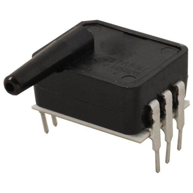
Dimensional Drawings DIP Packages figure 6. DiP Package Dimensional Drawings (for reference only: mm [in].) Dimensions DiP nn: No ports 0,25 5,44 [0.010] 10,0 [0.214] [0.39] 8 7 6 5 PORT 1 PORT 2 [06.,29795] [103.5,33] PIN 1 INDICATOR 1 2 3 4 9,24 2,54 TYP. [0.364] [0.100] 10,85 [0.427] 8X 0,46 [0.018] DIP AN: SIngle axial barbed port [10.35,4751] [00.,02150] 10,0 [0.39] 8 7 6 5 7,95 [0.313] 6,2 [0.24] 13,3 [04.,19934 ] PORT 2 [06.,29795] [0.53] PIN 1 PORT 1 INDICATOR 1 2 3 4 9,24 2,54 TYP. [0.364] [0.100] 11,21 [0.441] 8X 0,46 [0.018] DiP ln: Single axial barbless 13,75 port [0.541] 0,25 5,80 [0.010] 10,0 [0.228] [0.39] 8 7 6 5 6,99 13,3 PORT 2 [0.275] [0.53] PORT 1 PIN 1 INDICATOR [ 0 2.0,4977 ] 1 2 [ 0 2 .,315 0 4 0 4T] YP. [09.,32644] 11,21 [0.441] 6,95 [0.274] 1,00 [0.039] 8X 0,46 [0.018] sensing.honeywell.com 19
Dimensional Drawings DIP Packages figure 6. DiP Package Dimensional Drawings (continued) Dimensions DIP RN: Single radial barbed port 0,25 5,80 [0.010] 10,0 [0.228] [0.39] 8 7 6 5 4,2 13,3 [0.17] [0.53] PORT 1 PORT 2 6,99 [0.275] 1,93 [0.076] 1 2 3 4 9,24 2,54 TYP. [0.364] [0.100] 11,21 [0.441] 8X 0,46 [0.018] DiP rr: Dual radial barbed ports, same side 0,25 6,16 [0.010] 10,0 4,0 8 7 6 5 [0.242] [0.39] [0.16] 2X 1,93 PORT 1 13,3 [0.076] [0.53] 6,99 PORT 2 PORT 1 PORT 2 [0.275] 4,65 [0.183] 1 2 3 4 9,24 2,54 TYP. [0.364] [0.100] 11,21 [0.441] 3,78 [0.149] 8X 0,46 [0.018] DIP DR: Dual radial barbed ports, opposite sides [01.56,2706] [06.,21462] [00.,02150] [100.3,09] 8 7 6 5 2X 1,93 [0.076] 13,3 PORT 1 PORT 2 [06.,29795] [0.53] PORT 2 PORT 1 9,24 1 2 3 4 [0.364] [ 0 2.1,5040 ]TYP. [101.4,2411] 3,78 [0.149] 8X 0,46 [0.018] 20 sensing.honeywell.com
Dimensional Drawings DIP and SMT Packages figure 6. DiP Package Dimensional Drawings (continued) Dimensions DiP Jn: Single radial barbless port 9,91 7,58 [0.390] 6,75 [0.298] 1,9 [0.266] 3,28 3,28 9,40 [0.07] [0.129] [0.129] [0.370] 8 7 6 5 2,34 4,1 [0.092] PORT 1 13,3 [0.16] PORT 1 PORT 2 [0.53] 7,00 [0.276] 1 2 3 4 9,24 0,25 [0.364] [0.010] 11,92 [0.469] 6,70 [0.264] 8 X 0,461 [0.018] DIP JJ: Dual radial radial barbless ports, same side 9,91 6,51 [0.390] [0.256] 4,76 2 X [0 6.2,7656] 8 7 6 5 [03.,12289] [02.,02817] [09.,34700] [0.187] [01.0,97] 2X 2,34 4,1 [0.092] PORT 1 13,3 [0.16] PORT 1 PORT 2 [0.53] 7,00 [0.276] 4,1 4,2 [0.16] [0.16] 1 2 [ 0 23. ,1 5 0 440] [09.,32644] [00.,02150] 11,92 [0.469] 1,94 [0.076] 8 X 0,46 [0.018] figure 7. SMt Package Dimensional Drawings (for reference only: mm [in].) Dimensions SMt nn: No ports 5,44 10,0 [0.214] [0.39] 8 7 6 5 PORT 1 PORT 2[06.,29795] [103.5,33] PIN 1 INDICATOR 1 2 2 3,5 4 T4Y P. [04.,18809] 8 X [0 0.0,4168] [0.100] 6,41 [0.252] sensing.honeywell.com 21
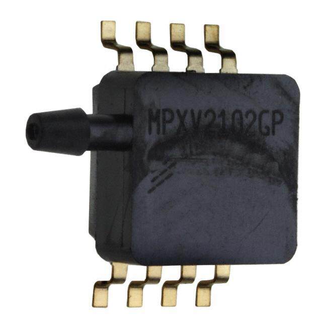
Dimensional Drawings SMT Packages figure 7. SMt Package Dimensional Drawings (continued) Dimensions SMt An: Single axial barbed port 13,75 [0.541] 10,0 [0.39] 8 7 6 5 7,95 [0.313] [ 04.,19934 D]IA. PORT 2[06.,29795] [103.5,33] PIN 1 PORT 1 INDICATOR 1 2 3 4 4,80 8X 0,46 2,54 TYP. [0.189] [0.018] [0.100] 6,77 [0.266] SMt ln: Single axial barbless port 13,75 [0.541] 5,80 10,0 8 7 6 5 [0.228] [0.394] 13,3 6,99 [0.53] PORT 2[0.275] PORT 1 PIN 1 2,47 DIA. INDICATOR [0.097] 1 2 3 4 4,80 8X 0,46 2,54 TYP. [0.189] [0.018] [0.100] 6,77 [0.266] SMt rn: Single radial barbed port 5,80 10,0 [0.228] [0.39] 8 7 6 5 [01.35,33] [04.,127] 6,99 PORT 1 PORT 1 PORT 2 [0.275] 1,93 DIA. [0.076] 1 2 3 4 4,80 8X 0,46 2,54 TYP. [0.189] [0.018] [0.100] 6,77 [0.266] 22 sensing.honeywell.com
Dimensional Drawings SMT Packages figure 7. SMt Package Dimensional Drawings (continued) Dimensions SMt rr: Dual radial barbed ports, same side 6,16 10,0 4,0 [0.242] [0.39] [0.16] 8 7 6 5 2X 1,93 DIA. PORT 1 13,3 [0.076] [0.53] 6,99 PORT 2 PORT 1 PORT 2 [0.275] 4,6 [0.18] 1 2 3 4 4,80 8X 0,46 2,54 TYP. [0.189] [0.018] [0.100] 6,77 [0.266] 3,78 [0.149] SMT DR: Dual radial barbed ports, opposite sides 15,8 [0.62] 2X 2,93 6,16 10,0 [0.115] [0.242] [0.39] 8 7 6 5 2X[ 01.,09736 D]IA. [06.,29795] [103.5,33] PORT 1 PORT 2 1 2 3 4 4,80 8X 0,46 2,54 TYP. [0.189] [0.018] [0.100] 3,78 6,77 [0.149] [0.266] SMt Jn: Single radial barbless port 6,51 9,91 [0.256] [0.390] 6,75 3,28 2,21 9,40 1,87 [0.266] [0.129] [0.087] [0.370] [0.074] 8 7 6 5 2,34 4,15 [0.092] PORT 1 13,3 [0.163] PORT 1 [0.53] 7,00 6,98 PORT 2 [0.276] [0.275] 1 2 [ 0 2 3.,1 5 0 4 04] 7,48 [04.,18809] 8 X[0 0.0,41681] 8 X[0 1.0,2580] [0.294] 5,38 [0.212] sensing.honeywell.com 23
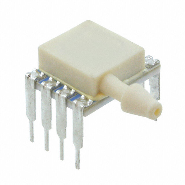
Dimensional Drawings SMT and SIP Packages figure 7. SMt Package Dimensional Drawings (continued) Dimensions SMT JJ: Dual radial barbless ports, same side 9,91 7,58 [0.390] 2X 6,75 [0.298] 9,40 4,76 [0.266] 3,28 [0.370] [0.187] 8 7 6 5 [0.129] 2X 2,34 4,15 [0.092] PORT 1 PORT 1 PORT 2 [0.163] 7,00 6,98 13,3 [0.276] [0.275] [0.53] 4,162 [0.1639] 1 2 [ 0 23. ,1 5 0 440] 8,36 [05.,16889] 8 X[0 0.0,41681] 8 X[0 1.0,2580] [0.329] 5,38 [0.212] figure 8. SiP Package Dimensional Drawings (for reference only: mm [in].) Dimensions SiP nn: No ports 10,0 4,87 [0.39] [0.192] 10,0 PORT 1 PORT 2 [0.39] 15,2 [0.60] 1 2 3 4 0,25 4X 0,51 [0.010] 2,54 TYP. [0.020] [0.100] SIP AA: Dual axial barbed ports, opposite sides 10,0 22,06 [0.39] [0.869] 10,0 PORT 1 PORT 2 [0.39] 2X 4.93 DIA. [0.194] 15,2 [0.60] (cid:20)(cid:3)(cid:3)(cid:3)(cid:3)(cid:21)(cid:3)(cid:3)(cid:3)(cid:3)(cid:22)(cid:3)(cid:3)(cid:3)(cid:3)(cid:23)(cid:3)(cid:3) 0,25 4X 0,51 [0.010] 2,54 TYP. [0.020] [0.100] 24 sensing.honeywell.com
Dimensional Drawings SIP Packages figure 8. SiP Package Dimensional Drawings (continued) Dimensions SiP An: Single axial barbed port 13,75 10,0 [0.541] [0.39] 10,0 PORT 1 PORT 2 [0.39] 4.93 DIA. [0.194] 15,2 [0.60] (cid:20)(cid:3)(cid:3)(cid:3)(cid:3)(cid:21)(cid:3)(cid:3)(cid:3)(cid:3)(cid:22)(cid:3)(cid:3)(cid:3)(cid:3)(cid:23)(cid:3)(cid:3) 0,25 4X 0,51 [0.010] 2,54 TYP. [0.020] [0.100] SIP LN: Single axial barbless port 10,0 13,75 [0.39] [0.541] 10,0 PORT 2 [0.39] PORT 1 2,47 DIA. [0.097] 15,2 [0.60] 1 2 3 4 0,25 4X 0,51 [0.010] 2,54 TYP. [0.020] [0.100] SiP ff: Fastener mount, dual axial barbed ports, opposite sides 29,48 27,20 [1.161] [1.071] 23,12 10,44 [0.910] [0.411] 17,78 [0.700] PORT 2 PORT 1 2X 3.94 DIA. [0.155] 2X 4,78 DIA. [0.188] 20,16 [0.794] (cid:20)(cid:3)(cid:3)(cid:3)(cid:3)(cid:21)(cid:3)(cid:3)(cid:3)(cid:3)(cid:22)(cid:3)(cid:3)(cid:3)(cid:3)(cid:23)(cid:3)(cid:3) 0,25 2,54 TYP. 4X 0,51 [0.010] [0.100] [0.020] sensing.honeywell.com 25
Dimensional Drawings SIP Packages figure 8. SiP Package Dimensional Drawings (continued) Dimensions SiP fn: Fastener mount, single axial barbed port 29,48 [1.161] 16,38 23,12 [0.645] [0.910] 17,78 [0.700] (cid:51)(cid:50)(cid:53)(cid:55)(cid:3)(cid:21) (cid:51)(cid:50)(cid:53)(cid:55)(cid:3)(cid:20) 2X 3.94 DIA. 4.78 DI.A [0.155] [0.188] 20,16 [0.794] (cid:20)(cid:3)(cid:3)(cid:3)(cid:3)(cid:21)(cid:3)(cid:3)(cid:3)(cid:3)(cid:22)(cid:3)(cid:3)(cid:3)(cid:3)(cid:23)(cid:3)(cid:3) 0,25 2,54 TYP. 4X 0,51 [0.010] [0.100] [0.020] SiP gn: Ribbed fastener mount, single axial barbed 27,96 port [1.101] 21,60 16,51 [0.850] [0.650] 19,06 [0.750] PORT 2 PORT 1 2X 3,94 DIA. [0.155] 4.78 DIA. [0.188] 10,63 [0.418] (cid:20)(cid:3)(cid:3)(cid:3)(cid:3)(cid:21)(cid:3)(cid:3)(cid:3)(cid:3)(cid:22)(cid:3)(cid:3)(cid:3)(cid:23)(cid:3)(cid:3) 0,25 4X 0,51 [0.010] 2,54 TYP. [0.020] [0.100] SiP nB: Fastener mount, dual axial ports, same side 27,31 [1.075] 25,3 21,60 [0.996] [0.850] 2X 4,80 DIA. [0.189] PORT 2 22,87 [0.900] 2X 3.50 DIA. [0.138] PORT 1 13 [0.52] (cid:23)(cid:3)(cid:3)(cid:3)(cid:3)(cid:22)(cid:3)(cid:3)(cid:3)(cid:3)(cid:21)(cid:3)(cid:3)(cid:3)(cid:3)(cid:20)(cid:3)(cid:3) 0,25 4X 0,51 [0.010] 2,54 TYP. [0.020] [0.100] 26 sensing.honeywell.com
Dimensional Drawings SIP Packages figure 8. SiP Package Dimensional Drawings (continued) Dimensions SIP RN: Single radial barbed port 10,0 [0.39] 5,80 [0.228] PORT 1 PORT 1 10,0 [0.39] PORT 2 1,92 DIA. [0.076] 15,2 [0.60] 1 2 3 4 0,25 4X 0,51 [0.010] 2,54 TYP. [0.020] [0.100] SIP RR: Dual radial barbed ports, same side 10,0 6,16 [0.39] [0.243] PORT 1 PORT 1 10,0 PORT 2 [0.39] PORT 2 2X 1,92 DIA. [0.076] 15,2 [0.60] 1 2 3 4 0,25 4X 0,51 [0.010] 2,54 TYP. [0.020] [0.100] SIP DR: Dual radial barbed ports, opposite sides 15,8 [0.62] 10,0 6,16 [0.39] [0.243] 10,0 [0.39] PORT 2 PORT 1 2X 4.93 DIA. [0.194] 15,2 [0.60] 1 2 3 4 0,25 4X 0,51 [0.010] 2,54 TYP. [0.020] [0.100] sensing.honeywell.com 27
Dimensional Drawings SIP Packages figure 8. SiP Package Dimensional Drawings (continued) Dimensions SIP JN: Single radial barbless port 7,58 10,0 6,75 [0.298] [0.39] 1,7 [0.266] 3,28 2,2 9,40 [0.07] 1,9 [ 0 2.0,3942] PORT 1 [0.129] [0.087] [0.370] [0.07] 7,00 [0.276] PORT 2 10,0 [0.39] 25,0 [0.98] 15,20 [0.598] [ 0 1.0,1445] 1 2 3 4 4 X[0 0.0,5210] [ 0 2.0,18] [ 0 2.1,5040 ]TYP. SIP JJ: Dual radial barbless ports, same side 7,58 6,75 [0.298] 1,7 4,76 2 X [ 0 2.0,3942] P[0O.2R6T6 ]1 [03.,12289] [010.3,09] [0.07] [0.187] [01.,097] 5,8 7,00 [0.276] 10,0 [0.23] [0.39] 4,2 PORT 2 [0.16] 25,0 [0.98] 15,20 [0.598] [ 0 1.0,1445] 1 2 3 4 4 X[0 0.0,5210] [ 0 2.0,18] [ 0 2.1,5040 ]TYP. SIP HH: Fastener mount dual 29,62 10,58 radial barbed ports, same side [1.166] [0.416] 23,12 [0.910] 6,64 [0.261] PORT 2 PORT 1 PORT 2 PORT 1 28,96 [1.140] 11,27 [0.444] (cid:20)(cid:3)(cid:3)(cid:3)(cid:3)(cid:21)(cid:3)(cid:3)(cid:3)(cid:3)(cid:22)(cid:3)(cid:3)(cid:3)(cid:23)(cid:3)(cid:3) 0,25 2,54 TYP. 4X 0,51 [0.010] [0.100] [0.020] 28 sensing.honeywell.com
Dimensional Drawings SIP Packages figure 8. SiP Package Dimensional Drawings (continued) Dimensions SIP HN: Fastener mount single radial barbed port 23,12 [0.910] 7,97 [0.314] 4,78 DIA. [0.188] (cid:51)(cid:50)(cid:53)(cid:55)(cid:3)(cid:20) 28,96 [1.140] PORT 2 2X 3,94 DIA. [0.155] 11,27 [0.444] (cid:20)(cid:3)(cid:3)(cid:3)(cid:3)(cid:21)(cid:3)(cid:3)(cid:3)(cid:22)(cid:3)(cid:3)(cid:3)(cid:23)(cid:3)(cid:3) 0,25 2,54 TYP. 4X 0,51 [0.010] [0.100] [0.020] SIP MN: Manifold mount, outer diameter seal 5,36 PORT 2 [0.211] PORT 1 15,24 .DIA [0.600] 12,5 [0.49] 0,25 (cid:20)(cid:3)(cid:3)(cid:3)(cid:3)(cid:21)(cid:3)(cid:3)(cid:3)(cid:3)(cid:22)(cid:3)(cid:3)(cid:3)(cid:3)(cid:23)(cid:3)(cid:3) 4X 0,51 [0.010] 2,54 TYP. [0.020] [0.100] SIP SN: Manifold mount, inner diameter seal PORT 2 5,1 12,57 [0.495] [0.20] PORT 1 13,11 [0.516] 15,6 [0.61] 1 2 3 4 4X 0,51 2,54 TYP. [0.020] [0.100] sensing.honeywell.com 29
Pinouts, PCB Pad Layout table 11. Pinouts for DiP and SMt Packages output type Pin 1 Pin 2 Pin 3 Pin 4 Pin 5 Pin 6 Pin 7 Pin 8 I2C GND V SDA SCL NC NC NC NC supply SPI GND V MISO SCLK SS NC NC NC supply Analog NC V V GND NC NC NC NC supply out table 12. Pinouts for SiP Packages output type Pin 1 Pin 2 Pin 3 Pin 4 I2C GND V SDA SCL supply Analog NC V V GND supply out figure 9. recommended PCB Pad layouts DiP SMt SiP 1,143 [0.045] 0,813 0,914 [0.032] 13,08 2,032 [0.036] [0.515] [0.080] 9,40 [0.370] 2,54 [0.100] 2,54 2,54 [0.100] [0.100] 30 sensing.honeywell.com
TruStability® Board Mount Pressure Sensors Portfolio Overview table 13. truStability® Board Mount Pressure Sensors Portfolio overview Series Characteristic HSC SSC tSC nSC Package: DIP (Dual In-Line Pin) SMT (Surface Mount Technology) SIP (Single In-Line Pin) option: dry gases only, no diagnostics (all pressure ranges) dry gases only, diagnostics on (all pressure ranges) — — liquid media on port 1, no diagnostics (±60 mbar to ±10 bar | ±6 kPa to ±1 MPa | ±1 psi to ±150 psi) liquid media on port 1, diagnostics on (±60 mbar to ±10 bar | ±6 kPa to ±1 MPa | ±1 psi to ±150 psi) — — Pressure range: Absolute: 1 bar to 10 bar | 100 kPa to 1 MPa | 15 psi to 150 psi — Differential: ±60 mbar to ±10 bar | ±6 kPa to ±1 MPa | ±1 psi to ±150 psi ±1.6 mbar to ±40 mbar | ±160 Pa to ±4 kPa | ±0.5 inHO to ±30 inHO — 2 2 Gage: 60 mbar to 10 bar | 6 kPa to 1 MPa | 1 psi to 150 psi 2.5 mbar to 40 mbar | 250 Pa to 4 kPa | 1 inHO to 30 inHO — 2 2 temperature compensated — Amplified — — output type: analog digital (SPI and I2C) — — transfer function: 10% to 90% of Vsupply (analog), 214 counts (digital) — — 5% to 95% of Vsupply (analog), 214 counts (digital) — — 5% to 85% of Vsupply (analog), 214 counts (digital) — — 4% to 94% of Vsupply (analog), 214 counts (digital) — — Supply voltage: 3.3 Vdc — — 5.0 Vdc — — 1.5 Vdc to 12.0 Vdc (for pressure ranges >60 mbar | 6 kPa | 1 psi) — — 2.7 Vdc to 6.5 Vdc (for pressure ranges <40 mbar | 4 kPa | 20 inHO) — — — 2 Accuracy <0.25 %fSS BfSl Compensated temperature range: -20 °C to 85 °C [-4 °F to 185 °F] — — — 0 °C to 85 °C [32 °F to 185 °F] — — — 0 °C to 50 °C [32 °F to 122 °F] — — — operating temperature range: -20 °C to 85 °C [-4 °F to 185 °F] — — — -40 °C to 85 °C [-40 °F to 185 °F] — total error Band: down to ±1% Full Scale Span max. — — — down to ±2% Full Scale Span max. — — — sensing.honeywell.com 31
ADDitionAl inforMAtion WARNING The following associated literature is available at sensing.honeywell.com: PERSONAL INJURY • Product line guide DO NOT USE these products as safety or emergency stop • Product range guide devices or in any other application where failure of the product • Product nomenclature tree could result in personal injury. • Installation instructions Failure to comply with these instructions could result in • Application information death or serious injury. • Technical notes: - I2C Communications with Honeywell Digital Output WARNING Pressure Sensors MISUSE OF DOCUMENTATION - SPI Communications with Honeywell Digital Output Pressure Sensors • The information presented in this product sheet is for reference only. Do not use this document as a product installation guide. • Complete installation, operation, and maintenance information is provided in the instructions supplied with each product. Failure to comply with these instructions could result in death or serious injury. wArrAnty/reMeDy Honeywell warrants goods of its manufacture as being free of defective materials and faulty workmanship. Honeywell’s standard product warranty applies unless agreed to otherwise by Honeywell in writing; please refer to your order acknowledgement or consult your local sales office for specific warranty details. If warranted goods are returned to Honeywell during the period of coverage, Honeywell will repair or replace, at its option, without charge those items it finds defective. the foregoing is buyer’s sole remedy and is in lieu of all other warranties, expressed or implied, including those of merchantability and fitness for a particular purpose. in no event shall Honeywell be liable for consequential, special, or indirect damages. While we provide application assistance personally, through our literature and the Honeywell website, it is up to the customer to determine the suitability of the product in the application. Specifications may change without notice. The information we supply is believed to be accurate and reliable as of this printing. However, we assume no responsibility for its use. 32 sensing.honeywell.com
Sales and Service Honeywell serves its customers through a worldwide network of sales offices, representatives and distributors. For application assistance, current specifications, pricing or name of the nearest Authorized Distributor, contact your local sales office or email us at info.sc@honeywell.com. Visit us on the Web at sensing.honeywell.com Phone and Fax: Asia Pacific +65 6355-2828 +65 6445-3033 Fax Europe +44 (0) 1698 481481 +44 (0) 1698 481676 Fax Latin America +1-305-805-8188 +1-305-883-8257 Fax USA/Canada +1-800-537-6945 +1-815-235-6847 +1-815-235-6545 Fax Sensing and Control Honeywell 1985 Douglas Drive North Golden Valley, MN 55422 50099148-A-EN IL50 August 2014 honeywell.com © 2014 Honeywell International Inc. All rights reserved.
Mouser Electronics Authorized Distributor Click to View Pricing, Inventory, Delivery & Lifecycle Information: H oneywell: HSCMRNN001BGAA5 HSCMRNN001BG2A5 HSCMRNN001PG2A3 HSCMAND1.6BGSA3 HSCMAND015PASA5 HSCMAND030PGAA5 HSCMAND015PA2A3 HSCMAND060PA3A3 HSCMAND150PA4A3 HSCMRRD001PG2A3 HSCSAND030PAAA5 HSCSAND100PGAA5 HSCSFFN005PDAA5 HSCSGNN001PGAA5 HSCSHHN060PDAA5 HSCSHNN001PGAA5 HSCSHNN150PGAA5 HSCSRRD001PD2A3 HSCSRRD001PG2A3 HSCDANV001PGSA3 HSCDANV005PG2A5 HSCDRRV001PD2A3 HSCMAND001PDSA5 HSCMLND001PGSA3 HSCMLND030PD2A3 HSCMRND030PD3A3 HSCMRRD001PDSA3 HSCMRRD001PDSA5 HSCMRRD100MDSA3 HSCMRRD400MG2A3 HSCSAND015PAAA5 HSCSNBD001PDAA5 HSCMLNN150PGAA5 HSCMRNT100MG2A3 HSCMRNV160MG2A3 HSCDDRD025MD2A5 HSCDDRD060MD2A5 HSCDLNN010BASA3 HSCDRRD001PG2A5 HSCDRRD002NDAA5 HSCDRRD002NDSA5 HSCDRRN001ND2A3 HSCDRRN001NDAA3 HSCDRRN001NDAA5 HSCDRRN002NDAA5 HSCDRRN002NGAA3 HSCDRRN002NGAA5 HSCDRRN005NGAA5 HSCMNNN002NGAA3 HSCMRND100PGSA3 HSCMRRD005NDSA5 HSCMRRN002ND2A3 HSCMRRN002NDAA5 HSCMRRN002NDSA3 HSCMRRN005NDAA5 HSCSAAN001NDAA5 HSCSDRN001NDAA5 HSCSFFD006MGAA5 HSCSMND004MGAA5 HSCSNBD001NDAA5 HSCSRRD001ND2A5 HSCSRRN002NGAA3 HSCMAND060PGAA5 HSCMAND2.5BGAA5 HSCMANT015PGSA5 HSCMANT005PGSA5 HSCMANT001PGSA5 HSCDANN005NDAA5 HSCDRRN002NG2A3 HSCDRRN005NDAA3 HSCMDRN002NGAA3 HSCMDRN002NGSA3 HSCMDRN004NGAA3 HSCMDRN004NGSA3 HSCMRRD001NDAA5 HSCMRRD010NDAA5 HSCMRRD030NDAA5 HSCMRRN001NDAA5 HSCMRRN005ND7A3 HSCSLNN030PAAA5 HSCDANN004NGAA5 HSCDANT001PG3A5 HSCDANT001PGAA5 HSCMANT100PG2A5 HSCMANV015PGAA5 HSCMLNN001PGAA3 HSCMRRD006MDSA3 HSCMRRN002ND4A3 HSCSFNT250MGAA5 HSCSFNT400MGAA5 HSCSNBN001NDAA5 HSCSRRD001NDAA5 HSCDANT015PGSA5 HSCDANT005PGSA5 HSCDANT001PGSA5 HSCMRRN001PDAA5 HSCMRRN015PGAA5 HSCMRRN100PGAA5 HSCMRRN030PAAA5 HSCMRRN160MDAA5