ICGOO在线商城 > 开发板,套件,编程器 > 评估板 - DC/DC 与 AC/DC(离线)SMPS > TPS23754EVM-420
 Datasheet下载
- 型号: TPS23754EVM-420
- 制造商: Texas Instruments
- 库位|库存: xxxx|xxxx
- 要求:
| 数量阶梯 | 香港交货 | 国内含税 |
| +xxxx | $xxxx | ¥xxxx |
查看当月历史价格
查看今年历史价格
TPS23754EVM-420产品简介:
ICGOO电子元器件商城为您提供TPS23754EVM-420由Texas Instruments设计生产,在icgoo商城现货销售,并且可以通过原厂、代理商等渠道进行代购。 TPS23754EVM-420价格参考¥750.90-¥750.90。Texas InstrumentsTPS23754EVM-420封装/规格:评估板 - DC/DC 与 AC/DC(离线)SMPS, TPS23754 - Special Purpose DC/DC, Power Over Ethernet 1, Isolated Outputs Evaluation Board。您可以下载TPS23754EVM-420参考资料、Datasheet数据手册功能说明书,资料中有TPS23754EVM-420 详细功能的应用电路图电压和使用方法及教程。
TPS23754EVM-420 是 Texas Instruments 推出的一款评估板,专为测试和评估 TPS23754 电源管理 IC 的性能而设计。该评估板主要用于 DC/DC 和 AC/DC(离线)开关电源(SMPS)应用。

其主要应用场景包括:

1. 工业电源系统:适用于需要高效、稳定供电的工业设备,如PLC、工业自动化控制设备等;
2. 通信设备:用于电信基础设施中的电源模块,提供可靠的电力转换与管理;
3. 服务器与网络设备:适合用于数据中心、交换机、路由器等对电源效率和密度要求高的场合;
4. 离线电源开发:支持从交流电网直接输入(AC适配器或离线电源),方便工程师进行AC/DC转换器的设计与验证;
5. 研发与原型设计:作为开发平台,帮助工程师快速评估TPS23754芯片在不同电路配置下的性能,加快产品开发周期。

该评估板具备良好的保护功能(如过流、过压保护),支持多种工作模式,具有高效率和低待机功耗的特点,非常适合用于高性能电源解决方案的开发与测试。
| 参数 | 数值 |
| 产品目录 | 编程器,开发系统半导体 |
| 描述 | EVAL MODULE FOR TPS23754-420电源管理IC开发工具 TPS23754 Eval Mod |
| 产品分类 | |
| 品牌 | Texas Instruments |
| 产品手册 | http://www.ti.com/lit/pdf/slvu301 |
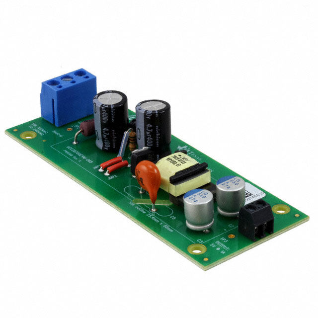
| 产品图片 |
|
| rohs | 否含铅 / 不受限制有害物质指令(RoHS)规范要求限制 |
| 产品系列 | 电源管理IC开发工具,Texas Instruments TPS23754EVM-420- |
| 数据手册 | 点击此处下载产品Datasheethttp://www.ti.com/lit/pdf/slvu301 |
| 产品型号 | TPS23754EVM-420 |
| 主要用途 | 特殊用途 DC/DC,以太网供电(POE) |
| 产品 | Evaluation Boards |
| 产品目录页面 | |
| 产品种类 | 电源管理IC开发工具 |
| 使用的IC/零件 | TPS23754 |
| 其它名称 | 296-24595 |
| 制造商产品页 | http://www.ti.com/general/docs/suppproductinfo.tsp?distId=10&orderablePartNumber=TPS23754EVM-420 |
| 功率-输出 | 25W |
| 参考设计库 | http://www.digikey.com/rdl/4294959902/4294959890/392 |
| 商标 | Texas Instruments |
| 尺寸 | 149.9 mm x 51.6 mm |
| 工具用于评估 | TPS23754 |
| 工厂包装数量 | 1 |
| 所含物品 | 板 |
| 接口类型 | Ethernet |
| 板类型 | 完全填充 |
| 标准包装 | 1 |
| 电压-输入 | 30 V ~ 57 V |
| 电压-输出 | 5V |
| 电流-输出 | 5A |
| 相关产品 | /product-detail/zh/TPS23754PWP/296-24369-5-ND/2051742/product-detail/zh/TPS23754PWP-1/296-24370-2-ND/2051743/product-detail/zh/TPS23754PWP-1/296-24370-5-ND/2051748/product-detail/zh/TPS23754PWP-1/296-24370-6-ND/2051753 |
| 稳压器拓扑 | 降压 |
| 类型 | Hot Swap Voltage Controllers |
| 输入电压 | 0 V to 57 V |
| 输出和类型 | 1,隔离 |
| 输出电压 | 5 V |
| 频率-开关 | 250kHz |


- 商务部:美国ITC正式对集成电路等产品启动337调查
- 曝三星4nm工艺存在良率问题 高通将骁龙8 Gen1或转产台积电
- 太阳诱电将投资9.5亿元在常州建新厂生产MLCC 预计2023年完工
- 英特尔发布欧洲新工厂建设计划 深化IDM 2.0 战略
- 台积电先进制程称霸业界 有大客户加持明年业绩稳了
- 达到5530亿美元!SIA预计今年全球半导体销售额将创下新高
- 英特尔拟将自动驾驶子公司Mobileye上市 估值或超500亿美元
- 三星加码芯片和SET,合并消费电子和移动部门,撤换高东真等 CEO
- 三星电子宣布重大人事变动 还合并消费电子和移动部门
- 海关总署:前11个月进口集成电路产品价值2.52万亿元 增长14.8%

PDF Datasheet 数据手册内容提取
User's Guide SLVU301–April2009 TPS23754EVM-420 EVM: Evaluation Module for TPS23754 This User’s Guide describes the TPS23754 EVM (TPS23754EVM-420). TPS23754EVM-420 contains evaluation and reference circuitry for the TPS23754. The TPS23754 is an IEEE 802.3at compliant powered device (PD) controller and power supply controller optimized for isolated converter topologies. TPS23754EVM-420istargetedat25W,synchronousflybackconverterapplications. Contents 1 Description.................................................................................................................... 2 1.1 Features.............................................................................................................. 2 1.2 Applications.......................................................................................................... 2 2 ElectricalSpecifications..................................................................................................... 2 3 Schematic..................................................................................................................... 3 4 GeneralConfigurationandDescription................................................................................... 4 4.1 PhysicalAccess..................................................................................................... 4 5 TestSetup.................................................................................................................... 5 6 TPS23754EVM-420TypicalPerformanceData......................................................................... 5 6.1 5VDC/DCEfficiency............................................................................................... 5 7 EVMAssemblyDrawingsandLayoutGuidelines....................................................................... 6 7.1 PCBDrawings....................................................................................................... 6 7.2 LayoutGuidelines................................................................................................... 7 7.3 EMIContainment................................................................................................... 7 8 BillofMaterials............................................................................................................... 8 ListofFigures 1 TPS23754EVM-420Schematic............................................................................................ 3 2 TypicalTPS23754EVM-420TestSetup.................................................................................. 5 3 TPS23754EVM-420EfficiencyWith5VOutput.......................................................................... 5 4 TopSideLayout.............................................................................................................. 6 5 BottomSideLayout.......................................................................................................... 6 ListofTables 1 TPS23754EVM-420ElectricalandPerformanceSpecifications....................................................... 2 2 ConnectorFunctionality..................................................................................................... 4 3 TestPointsandIndicators.................................................................................................. 4 4 TPS23754EVM-420BillofMaterials ..................................................................................... 8 SLVU301–April2009 TPS23754EVM-420EVM:EvaluationModuleforTPS23754 1 SubmitDocumentationFeedback
Description www.ti.com 1 Description TPS23754EVM-420willallowreferencecircuitryevaluationoftheTPS23754.Itcontainsinputandoutput powerconnectorsandanarrayofonboardtestpointsforcircuitevaluation.Anactiveclamp,12V,30W EVMisalsoavailable,seeSLVU304. 1.1 Features • Efficient,generalmarketdesign – Selfdriven,synchronousrectifiedsecondary – 25Woutputpowerfrompoweroverethernet(PoE),30Woutputpowerfroma48Vadapter – OperatesfromeitherPoEorexternaladaptors(24and48V) – 5Voutputvoltage 1.2 Applications • VoiceoverInternetProtocol–IPtelephones • WirelessLAN–WirelessAccessPoints • Security–WiredIPcameras 2 Electrical Specifications Table1.TPS23754EVM-420ElectricalandPerformanceSpecifications Parameter TestConditions Min Typ Max Unit POWERINTERFACE InputVoltage AppliedtothepowerpinsofconnectorsJ1orJ3 0 57 V OperatingVoltage Afterstartup 30 57 V Risinginputvoltage 36 InputUVLO V Fallinginputvoltage 30 Detctionvoltage Atdeviceterminals 1.6 10 V Classificationvoltage Atdeviceterminals 10 23 V Classificationcurrent Rclass=63.5W 36 44 mA Inrushcurrent-limit 100 180 mA Operatingcurrent-limit 850 1100 mA DC/DCCONVERTER 21.6V£ Vin£ 57V, Outputvoltage ILOAD£ ILOAD(max) 5Voutput 4.75 5.00 5.25 V Outputcurrent 21.6V£ Vin£ 57V 5Voutput 5 A Outputripplevoltage,peak-to-peak Vin=44V,ILOAD=5A 5Voutput 50 mV Efficency,end-to-end Vin=44V,ILOAD=5A 5Voutput 85% Switchingfrequency 225 275 kHz 2 TPS23754EVM-420EVM:EvaluationModuleforTPS23754 SLVU301–April2009 SubmitDocumentationFeedback
www.ti.com Schematic 3 Schematic + + + + Figure1.TPS23754EVM-420Schematic SLVU301–April2009 TPS23754EVM-420EVM:EvaluationModuleforTPS23754 3 SubmitDocumentationFeedback
GeneralConfigurationandDescription www.ti.com 4 General Configuration and Description 4.1 Physical Access Table2liststheTPS23754EVM-420connectorfunctionalityandTable3describesthetestpoint availability. Table2.ConnectorFunctionality Connector Label Description Externaladapterinput.J10(lowside)andJ4(highside)canselectweathertheadapterisatthe J3 ADAPTER PDcontrollerinput(VDDtoVSS)orattheconverterinput(VDD1toCOM).J9isinstalledto selectAPDfunctionandJ8isinstalledtoselectthePPDfunction. J11 VOUT Outputvoltageconnector J2 EthernetPower Ethernetpowerinputconnector. J1 EthernetData Ethernetdataportconnector TP5 EarthGND EarthGNDconnection Table3.TestPointsandIndicators TestPoint Color Label Description TP8 BLK GND Secondaryside(output)grounds(GND) TP9 RED VC DC/DCconverterbiassupply TP10 ORG DRAIN DrainterminaloftheprimarysideswitchingMOSFET TP12 BLK VSS PoEinput,lowside TP14,TP15 BLK COM DC/DCconverterreturn TP18 ORG LOOP CanbeusedwithTP7foroverallfeedbackloopmeasurements. TP7 RED VOUT DC/DCconverteroutputvoltage. TP19 WHT CTL Controlloopinputtothepulsewidthmodulator TP13 WHT CS DC/DCconverterprimarysideswitchingMOSFETcurrentsense(deviceside). TP17 RED VB Biasvoltageregulator TP11 WHT GATE GatedrivefortheprimarysideswitchingMOSFET TP16 WHT GAT2 GatedriveforthesecondarysideMOSFET TP6 RED VDD PDcontrollerhighsidevoltage. TP1 RED ADPV Adapterinputvoltage TP4 WHT T2P Type2PSEoutputfromTPS23754 TP2 WHT PPD ConnectedtoPPDpinofTPS23754 TP3 WHT APD ConnectedtoAPDpinofTPS23754 TP5 WHT EarthGND EarthGNDcommonterminationpointforchassisterminators D4 RED T2P Type2PSEindicator.RemovetheshuntonJ5toinhibittheT2Pindicator. D2 GRN COM VDD1-COMvoltagepresent.RemovetheshuntonJ6toinhibittheCOMindicator. D3 GRN OUT Outputpowerindicator.RemovetheshuntonJ7toinhibittheoutputpowerindicator. CL1providesaconnectionbetweenVDDandVDD1shortingoutD13.Removingthe CL1 NA CL1 shortatCL1allowscertainpowersourcepriorityschemestobetested. 4 TPS23754EVM-420EVM:EvaluationModuleforTPS23754 SLVU301–April2009 SubmitDocumentationFeedback
www.ti.com TestSetup 5 Test Setup Figure2showsatypicaltestsetupforTPS23754EVM-420.Inputvoltagecanbeappliedasdescribedin Table2. AUX Power Source J3 PSE Or (Ethernet Cable) J2 GND Power Supply TPS23754EVM-420 J11 R LOAD VOUT Data to PHY J1 (Ethernet Cable) Figure2.TypicalTPS23754EVM-420TestSetup 6 TPS23754EVM-420 Typical Performance Data 6.1 5V DC/DC Efficiency Figure3illustratesthreedifferent48VDCinputefficiencyplots: 1. PoE,48VfromJ2 2. Converteronly48V 3. Adapter48VfromJ3 95 Converter 48V 90 85 % 80 PoE 48V Adapter 48V y - nc 75 e ci Effi 70 65 60 55 50 0 0.5 1 1.5 2 2.5 3 3.5 4 4.5 5 I - Output Current -A O Figure3.TPS23754EVM-420EfficiencyWith5VOutput SLVU301–April2009 TPS23754EVM-420EVM:EvaluationModuleforTPS23754 5 SubmitDocumentationFeedback
EVMAssemblyDrawingsandLayoutGuidelines www.ti.com 7 EVM Assembly Drawings and Layout Guidelines 7.1 PCB Drawings Figure4andFigure5showscomponentplacementandlayout. Figure4.TopSideLayout Figure5.BottomSideLayout 6 TPS23754EVM-420EVM:EvaluationModuleforTPS23754 SLVU301–April2009 SubmitDocumentationFeedback
www.ti.com EVMAssemblyDrawingsandLayoutGuidelines 7.2 Layout Guidelines ThelayoutofthePoEfrontendshouldfollowpowerandEMI/ESDbestpracticeguidelines.Abasicsetof recommendationsinclude: • Partsplacementmustbedrivenbypowerflowinapoint-to-pointmanner;RJ-45,Ethernettransformer, diodebridges,TVSand0.1-m Fcapacitor,andTPS23754converterinputbulkcapacitor. • Allleadsshouldbeasshortaspossiblewithwidepowertracesandpairedsignalandreturn. • Thereshouldnotbeanycrossoversofsignalsfromonepartoftheflowtoanother. • SpacingconsistentwithsafetystandardslikeIEC60950mustbeobservedbetweenthe48-Vinput voltagerailsandbetweentheinputandanisolatedconverteroutput. • TheTPS23754shouldbelocatedoversplit,localgroundplanesreferencedtoVSSforthePoEinput andtoCOM/RTNfortheconverter.WhereasthePoEsidemayoperatewithoutagroundplane,the convertersidemusthaveone.Logicgroundandpowerlayersshouldnotbepresentunderthe Ethernetinputortheconverterprimaryside. • LargecopperfillsandtracesshouldbeusedonSMTpower-dissipatingdevices,andwidetracesor overlaycopperfillsshouldbeusedinthepowerpath. TheDC/DCConverterlayoutcanbenefitfrombasicrulessuchas: • Pairsignalstoreduceemissionsandnoise,especiallythepathsthatcarryhigh-currentpulseswhich includethepowersemiconductorsandmagnetics. • Minimizetracelengthofhighcurrent,powersemiconductors,andmagneticcomponents. • Wherepossible,useverticalpairing. • Usethegroundplanefortheswitchingcurrentscarefully. • Keepthehigh-currentandhigh-voltageswitchingawayfromlow-levelsensingcircuitsincludingthose outsidethepowersupply. • Properspacingaroundthehigh-voltagesectionsoftheconverter. 7.3 EMI Containment • Usecompactloopsfordv/dtanddi/dtcircuitpaths(powerloopsandgatedrives) • Useminimal,yetthermallyadequate,copperareasforheatsinkingofcomponentstiedtoswitching nodes(minimizeexposedradiatingsurface). • Usecoppergroundplanes(possiblestitching)andtoplayercopperfloods(surroundcircuitrywith groundfloods) • Use4layerPCBifeconomicallyfeasible(forbettergrounding) • Minimizetheamountofcopperareaassociatedwithinputtraces(tominimizeradiatedpickup) • Hidecopperassociatedwithswitchingnodesundershieldedmagneticswherepossible • Heatsinkthe“quietside”ofcomponentsinsteadofthe“switchingside”wherepossible(liketheoutput sideofinductor) • UseBobSmithterminations,BobSmithEFTcapacitor,andBobSmithplane • UseBobSmithplaneasgroundshieldoninputsideofPCB(creatingaphantomorliteralearth ground) • UseLCfilteratDC/DCinput • Dampenhighfrequencyringingonallswitchingnodesifpresent(allowforpossiblesnubbers) • Controlrisetimeswithgatedriveresistorsandpossiblysnubbers • Switchingfrequencyconsiderations • UseofEMIbridgecapacitoracrossisolationboundary(isolatedtopologies) • Observethepolaritydotoninductors(embednoisyend) • Useofferritebeadsoninput(allowforpossibleuseofbeadsor0ohmresistors) • Maintainphysicalseparationbetweeninput-relatedcircuitryandpowercircuitry(useferritebeadsas boundaryline) • Balanceefficiencyvs.Acceptablenoisemargin • Possibleuseofcommon-modeinductors • PossibleuseofintegratedRJ-45jacks(shieldedwithinternaltransformerandBobSmithterminations) SLVU301–April2009 TPS23754EVM-420EVM:EvaluationModuleforTPS23754 7 SubmitDocumentationFeedback
BillofMaterials www.ti.com • End-productenclosureconsiderations(shielding) 8 Bill of Materials Table4.TPS23754EVM-420BillofMaterials Count RefDes Value Description Size PartNumber MFR 1 C1 1nF Capacitor,Ceramic,100V,X7R,10% 0805 Std Std 2 C10,C11 1m F Capacitor,Ceramic,1m F,100V,X7R,15% 1210 Std Std 1 C14 10nF Capacitor,Ceramic,100V,X7R,10% 0603 Std Std 3 C15–C17 47m F Capacitor,Ceramic,10V,X5R,15% 1210 Std Std 2 C18,C19 330m F Capacitor,Aluminum,6.3V,20%inch 0.260· 0.276 EEVFK0J331XP Panasonic 1 C2 0.1m F Capacitor,Ceramic,100V,X7R,10% 0805 Std Std 1 C20 1m F Capacitor,Ceramic,16V,X7R,15% 0603 Std Std 2 C21,C32 1.0m F Capacitor,Ceramic,16V,X7R,10% 0603 Std Std 1 C22 1200pF Capacitor,Ceramic,50V,X7R,15% 0603 Std Std 1 C23 1000pF Capacitor,Ceramic,100V,X7R,15% 0603 Std Std 1 C24 2200pF Capacitor,Ceramic,2KV,X7R,15% 1812 Std Std 1 C25 1.0m F Capacitor,Ceramic,25V,X7R,10% 0805 Std Std 1 C26 22m F Capacitor,Aluminum,25V,20% 5· 5,8mm EEVFK1E220R Panasonic 2 C27,C28 0.47m F Capacitor,Ceramic,16V,X7R,15% 0603 Std Std 1 C29 3300pF Capacitor,Ceramic,50V,X7R,15% 0603 Std Std 4 C3–C6 0.01m F Capacitor,Ceramic,100V,X7R,15% 0603 Std Std 1 C30 27nF Capacitor,Ceramic,50V,X7R,15% 0603 Std Std 1 C31 10nF Capacitor,Ceramic,50V,X7R,15% 0603 Std Std 1 C7 1000pF Capacitor,Ceramic,2kV,X7R,15% 1210 Std Std 3 C8,C12,C13 0.1m F Capacitor,Ceramic,100V,X7R,15% 0805 Std Std 1 C9 47m F Capacitor,Aluminum,63V,– 20% 0.3280· 0.390inch EEVFK1J470P Panasonic 1 CL1 NA CurrentLoop,0.025holes 0.1200· 0.075inch NA NA 1 D1 B2100 Diode,Schottky,2-A,100-V SMB B2100-13 DiodesInc 2 D14,D18 SMAJ58A Diode,TVS,58-V,1W SMA SMAJ58A DiodesInc. 2 D15,D16 BAV20WS Diode,SmallSignal,250mA,150V SOD-323 BAV20WS MicroCommercial Components 2 D17,D19 BAV99 Diode,DualUltraFast,Series,200-mA,70-V SOT23 BAV99 Fairchild 2 D2,D3 LN1371G Diode,LED,Green,10-mA,2.6-mcd 0.1140· 0.049inch LN1371G Panasonic 1 D4 LN1271RAL Diode,LED,UltraBrightRed,10-mA,5-mcd 0.1140· 0.049inch LN1271RAL Panasonic 9 D5–D13 B1100 Diode,Schottky,1A,100V SMA B1100 Diodes,Inc 4 FB1–FB4 500 Bead,Ferrite,2000mA,60mW 1206 MI1206L501R-10 Steward 2 J1,J2 5520252-4 Connector,Jack,Modular,Rt.Angle,8POS 0.7050· 0.820inch 5520252-4 AMP 2 J3,J11 ED1514 TerminalBlock,2-pin,6-A,3,5mm 0.270· 0.25 ED1514 2 J4,J10 PTC36SAAN Header,Male3-pin,100milspacing,(36-pinstrip) 0.100inch0· 3 PTC36SAAN Sullins 5 J5–J9 PTC36SAAN Header,Male2-pin,100milspacing,(36-pinstrip) 0.100inch0· 2 PTC36SAAN Sullins 1 L1 3.3uH Inductor,SMT,2.0A,80-mW 4.450· 6.6mm DO1608C-332 Coilcraft 1 L2 0.33uH Inductor,SMT,6.26A,7.4-mW 0.300sq" DR74-R33 Cooper 1 Q1 SiR464DP MOSFET,NChannel,30V,29A,3mW PWRPAKS0-8 SiR464DP Vishay 1 Q2 Si7898DP MOSFET,NChannel,150V,4.8A,85-mW PWRPAKS0-8 Si7898DP Vishay 1 Q3 MMBT3906 Bipolar,PNP,40V,200mA,225mW SOT23 MMBT3906LT1 OnSemi 1 R1 100K Resistor,Chip,1/16W,1% 0603 Std Std 1 R12 39K Resistor,Chip,1/10W,1% 0805 Std Std 1 R13 24.9k Resistor,Chip,1/16W,1% 0603 Std Std 2 R14,R15 69.8K Resistor,Chip,1/16W,1% 0603 Std Std 1 R16 10 Resistor,Chip,1/10W,1% 0805 Std Std 1 R17 38.3k Resistor,Chip,1/16W,1% 0603 Std Std 1 R18 10 Resistor,Chip,1/16W,5% 0603 Std Std 8 TPS23754EVM-420EVM:EvaluationModuleforTPS23754 SLVU301–April2009 SubmitDocumentationFeedback
www.ti.com BillofMaterials Table4.TPS23754EVM-420BillofMaterials (continued) Count RefDes Value Description Size PartNumber MFR 1 R19 63.4 Resistor,Chip,1/10W,1% 0805 Std Std 1 R2 15K Resistor,Chip,1/4W,1% 1210 Std Std 1 R20 10 Resistor,Chip,1/16W,1% 0603 Std Std 3 R21 1k Resistor,Chip,1/16W,1% 0603 Std Std 1 R22 0.18 Resistor,Chip,1/2W,1% 2010 Std Std 2 R23,R28 10K Resistor,Chip,1/16W,1% 0603 Std Std 1 R24 499 Resistor,Chip,1/16W,1% 0603 Std Std 1 R25 2K Resistor,Chip,1/16W,1% 0603 Std Std 1 R26 49.9 Resistor,Chip,1/16W,1% 0603 Std Std 1 R27 604 Resistor,Chip,1/16W,1% 0603 Std Std 1 R29 41.2K Resistor,Chip,1/16W,1% 0603 Std Std 2 R3,R4 1K Resistor,Chip,1/16W,1% 0603 Std Std 1 R30 13.7K Resistor,Chip,1/16W,1% 0603 Std Std 1 R5 6.49K Resistor,Chip,1/16W,1% 0603 Std Std 1 R6 4.02K Resistor,Chip,1/16W,1% 0603 Std Std 1 R7 8.87K Resistor,Chip,1/16W,1% 0603 Std Std 4 R8–R11 75 Resistor,Chip,1/16W,1% 0603 Std Std 1 T1 ETH1-230LD XFMR,Mid-PowerPoEMagnetics S014Wide ETH1-230LD Coilcraft 1 T2 POE300F-50L Transformer,SMTForPoE/PD,25W,2.8A 0.8100· 1.181inch POE300F-50L Coilcraft 1 T3 PA0184 XFMR,SMTGateDrive 0.3550· 0.340inch PA0184 Pulse 5 TP1,TP6, 5010 TestPoint,Red,ThruHole 0.1250· 0.125inch 5010 Keystone TP7,TP9, TP17 3 TP10,TP13, 5013 TestPoint,Orange,ThruHole 0.1250· 0.125inch 5013 Keystone TP18 7 TP2–TP5, 5012 TestPoint,White,ThruHole 0.1250· 0.125inch 5012 Keystone TP11,TP16, TP19 4 TP8,TP12, 5011 TestPoint,Black,ThruHole 0.1250· 0.125inch 5011 Keystone TP14,TP15 1 U1 FOD817D IC,Optocoupler,70-V,300-600%CTR SMT-4PDIP FOD817DS Fairchild 1 U2 TPS23754PW IC,IEEE802.3atPoEInterfaceandIsolated PWP20 TPS23754PWP TI P ConverterController 1 U3 TCMT1107 IC,Photocoupler,3750VRMS,80-160%CTR MF4 TCMT1107 Vishay 1 U4 TLV431A IC,ShuntRegulator,6V,10mA,1% SOT23-5 TLV431ACDBVR TI 6 — Shunt,Black 100-mil 929950-00 3M 4 2566 RubberBumbers 2566 1 — PCB,5.90In· 2.03In· 0.062In HPA420 Any SLVU301–April2009 TPS23754EVM-420EVM:EvaluationModuleforTPS23754 9 SubmitDocumentationFeedback
EVALUATIONBOARD/KITIMPORTANTNOTICE TexasInstruments(TI)providestheenclosedproduct(s)underthefollowingconditions: Thisevaluationboard/kitisintendedforuseforENGINEERINGDEVELOPMENT,DEMONSTRATION,OREVALUATIONPURPOSES ONLYandisnotconsideredbyTItobeafinishedend-productfitforgeneralconsumeruse.Personshandlingtheproduct(s)musthave electronicstrainingandobservegoodengineeringpracticestandards.Assuch,thegoodsbeingprovidedarenotintendedtobecomplete intermsofrequireddesign-,marketing-,and/ormanufacturing-relatedprotectiveconsiderations,includingproductsafetyandenvironmental measurestypicallyfoundinendproductsthatincorporatesuchsemiconductorcomponentsorcircuitboards.Thisevaluationboard/kitdoes notfallwithinthescopeoftheEuropeanUniondirectivesregardingelectromagneticcompatibility,restrictedsubstances(RoHS),recycling (WEEE),FCC,CEorUL,andthereforemaynotmeetthetechnicalrequirementsofthesedirectivesorotherrelateddirectives. Shouldthisevaluationboard/kitnotmeetthespecificationsindicatedintheUser’sGuide,theboard/kitmaybereturnedwithin30daysfrom thedateofdeliveryforafullrefund.THEFOREGOINGWARRANTYISTHEEXCLUSIVEWARRANTYMADEBYSELLERTOBUYER ANDISINLIEUOFALLOTHERWARRANTIES,EXPRESSED,IMPLIED,ORSTATUTORY,INCLUDINGANYWARRANTYOF MERCHANTABILITYORFITNESSFORANYPARTICULARPURPOSE. Theuserassumesallresponsibilityandliabilityforproperandsafehandlingofthegoods.Further,theuserindemnifiesTIfromallclaims arisingfromthehandlingoruseofthegoods.Duetotheopenconstructionoftheproduct,itistheuser’sresponsibilitytotakeanyandall appropriateprecautionswithregardtoelectrostaticdischarge. EXCEPTTOTHEEXTENTOFTHEINDEMNITYSETFORTHABOVE,NEITHERPARTYSHALLBELIABLETOTHEOTHERFORANY INDIRECT,SPECIAL,INCIDENTAL,ORCONSEQUENTIALDAMAGES. TIcurrentlydealswithavarietyofcustomersforproducts,andthereforeourarrangementwiththeuserisnotexclusive. TIassumesnoliabilityforapplicationsassistance,customerproductdesign,softwareperformance,orinfringementofpatentsor servicesdescribedherein. PleasereadtheUser’sGuideand,specifically,theWarningsandRestrictionsnoticeintheUser’sGuidepriortohandlingtheproduct.This noticecontainsimportantsafetyinformationabouttemperaturesandvoltages.ForadditionalinformationonTI’senvironmentaland/or safetyprograms,pleasecontacttheTIapplicationengineerorvisitwww.ti.com/esh. NolicenseisgrantedunderanypatentrightorotherintellectualpropertyrightofTIcoveringorrelatingtoanymachine,process,or combinationinwhichsuchTIproductsorservicesmightbeorareused. FCCWarning Thisevaluationboard/kitisintendedforuseforENGINEERINGDEVELOPMENT,DEMONSTRATION,OREVALUATIONPURPOSES ONLYandisnotconsideredbyTItobeafinishedend-productfitforgeneralconsumeruse.Itgenerates,uses,andcanradiateradio frequencyenergyandhasnotbeentestedforcompliancewiththelimitsofcomputingdevicespursuanttopart15ofFCCrules,whichare designedtoprovidereasonableprotectionagainstradiofrequencyinterference.Operationofthisequipmentinotherenvironmentsmay causeinterferencewithradiocommunications,inwhichcasetheuserathisownexpensewillberequiredtotakewhatevermeasuresmay berequiredtocorrectthisinterference. MailingAddress:TexasInstruments,PostOfficeBox655303,Dallas,Texas75265 Copyright©2009,TexasInstrumentsIncorporated EVMWARNINGSANDRESTRICTIONS ItisimportanttooperatethisEVMwithintheinputvoltagerangeof0Vto57Vandtheoutputvoltagerangeof4Vto6V. Exceedingthespecifiedinputrangemaycauseunexpectedoperationand/orirreversibledamagetotheEVM.Iftherearequestions concerningtheinputrange,pleasecontactaTIfieldrepresentativepriortoconnectingtheinputpower. Applyingloadsoutsideofthespecifiedoutputrangemayresultinunintendedoperationand/orpossiblepermanentdamagetotheEVM. PleaseconsulttheEVMUser'sGuidepriortoconnectinganyloadtotheEVMoutput.Ifthereisuncertaintyastotheloadspecification, pleasecontactaTIfieldrepresentative. Duringnormaloperation,somecircuitcomponentsmayhavecasetemperaturesgreaterthan80(cid:176) C.TheEVMisdesignedtooperate properlywithcertaincomponentsabove80(cid:176) Caslongastheinputandoutputrangesaremaintained.Thesecomponentsincludebutare notlimitedtolinearregulators,switchingtransistors,passtransistors,andcurrentsenseresistors.Thesetypesofdevicescanbeidentified usingtheEVMschematiclocatedintheEVMUser'sGuide.Whenplacingmeasurementprobesnearthesedevicesduringoperation, pleasebeawarethatthesedevicesmaybeverywarmtothetouch. MailingAddress:TexasInstruments,PostOfficeBox655303,Dallas,Texas75265 Copyright©2009,TexasInstrumentsIncorporated
IMPORTANTNOTICE TexasInstrumentsIncorporatedanditssubsidiaries(TI)reservetherighttomakecorrections,modifications,enhancements,improvements, andotherchangestoitsproductsandservicesatanytimeandtodiscontinueanyproductorservicewithoutnotice.Customersshould obtainthelatestrelevantinformationbeforeplacingordersandshouldverifythatsuchinformationiscurrentandcomplete.Allproductsare soldsubjecttoTI’stermsandconditionsofsalesuppliedatthetimeoforderacknowledgment. TIwarrantsperformanceofitshardwareproductstothespecificationsapplicableatthetimeofsaleinaccordancewithTI’sstandard warranty.TestingandotherqualitycontroltechniquesareusedtotheextentTIdeemsnecessarytosupportthiswarranty.Exceptwhere mandatedbygovernmentrequirements,testingofallparametersofeachproductisnotnecessarilyperformed. TIassumesnoliabilityforapplicationsassistanceorcustomerproductdesign.Customersareresponsiblefortheirproductsand applicationsusingTIcomponents.Tominimizetherisksassociatedwithcustomerproductsandapplications,customersshouldprovide adequatedesignandoperatingsafeguards. TIdoesnotwarrantorrepresentthatanylicense,eitherexpressorimplied,isgrantedunderanyTIpatentright,copyright,maskworkright, orotherTIintellectualpropertyrightrelatingtoanycombination,machine,orprocessinwhichTIproductsorservicesareused.Information publishedbyTIregardingthird-partyproductsorservicesdoesnotconstitutealicensefromTItousesuchproductsorservicesora warrantyorendorsementthereof.Useofsuchinformationmayrequirealicensefromathirdpartyunderthepatentsorotherintellectual propertyofthethirdparty,oralicensefromTIunderthepatentsorotherintellectualpropertyofTI. ReproductionofTIinformationinTIdatabooksordatasheetsispermissibleonlyifreproductioniswithoutalterationandisaccompanied byallassociatedwarranties,conditions,limitations,andnotices.Reproductionofthisinformationwithalterationisanunfairanddeceptive businesspractice.TIisnotresponsibleorliableforsuchaltereddocumentation.Informationofthirdpartiesmaybesubjecttoadditional restrictions. ResaleofTIproductsorserviceswithstatementsdifferentfromorbeyondtheparametersstatedbyTIforthatproductorservicevoidsall expressandanyimpliedwarrantiesfortheassociatedTIproductorserviceandisanunfairanddeceptivebusinesspractice.TIisnot responsibleorliableforanysuchstatements. TIproductsarenotauthorizedforuseinsafety-criticalapplications(suchaslifesupport)whereafailureoftheTIproductwouldreasonably beexpectedtocauseseverepersonalinjuryordeath,unlessofficersofthepartieshaveexecutedanagreementspecificallygoverning suchuse.Buyersrepresentthattheyhaveallnecessaryexpertiseinthesafetyandregulatoryramificationsoftheirapplications,and acknowledgeandagreethattheyaresolelyresponsibleforalllegal,regulatoryandsafety-relatedrequirementsconcerningtheirproducts andanyuseofTIproductsinsuchsafety-criticalapplications,notwithstandinganyapplications-relatedinformationorsupportthatmaybe providedbyTI.Further,BuyersmustfullyindemnifyTIanditsrepresentativesagainstanydamagesarisingoutoftheuseofTIproductsin suchsafety-criticalapplications. TIproductsareneitherdesignednorintendedforuseinmilitary/aerospaceapplicationsorenvironmentsunlesstheTIproductsare specificallydesignatedbyTIasmilitary-gradeor"enhancedplastic."OnlyproductsdesignatedbyTIasmilitary-grademeetmilitary specifications.BuyersacknowledgeandagreethatanysuchuseofTIproductswhichTIhasnotdesignatedasmilitary-gradeissolelyat theBuyer'srisk,andthattheyaresolelyresponsibleforcompliancewithalllegalandregulatoryrequirementsinconnectionwithsuchuse. TIproductsareneitherdesignednorintendedforuseinautomotiveapplicationsorenvironmentsunlessthespecificTIproductsare designatedbyTIascompliantwithISO/TS16949requirements.Buyersacknowledgeandagreethat,iftheyuseanynon-designated productsinautomotiveapplications,TIwillnotberesponsibleforanyfailuretomeetsuchrequirements. FollowingareURLswhereyoucanobtaininformationonotherTexasInstrumentsproductsandapplicationsolutions: Products Applications Amplifiers amplifier.ti.com Audio www.ti.com/audio DataConverters dataconverter.ti.com Automotive www.ti.com/automotive DLP®Products www.dlp.com Broadband www.ti.com/broadband DSP dsp.ti.com DigitalControl www.ti.com/digitalcontrol ClocksandTimers www.ti.com/clocks Medical www.ti.com/medical Interface interface.ti.com Military www.ti.com/military Logic logic.ti.com OpticalNetworking www.ti.com/opticalnetwork PowerMgmt power.ti.com Security www.ti.com/security Microcontrollers microcontroller.ti.com Telephony www.ti.com/telephony RFID www.ti-rfid.com Video&Imaging www.ti.com/video RF/IFandZigBee®Solutions www.ti.com/lprf Wireless www.ti.com/wireless MailingAddress:TexasInstruments,PostOfficeBox655303,Dallas,Texas75265 Copyright©2009,TexasInstrumentsIncorporated