ICGOO在线商城 > TMCGD6SA1040C

 Datasheet下载
- 型号: TMCGD6SA1040C
- 制造商: C&K Components
- 库位|库存: xxxx|xxxx
- 要求:
| 数量阶梯 | 香港交货 | 国内含税 |
| +xxxx | $xxxx | ¥xxxx |
查看当月历史价格
查看今年历史价格
TMCGD6SA1040C产品简介:
ICGOO电子元器件商城为您提供TMCGD6SA1040C由C&K Components设计生产,在icgoo商城现货销售,并且可以通过原厂、代理商等渠道进行代购。 提供TMCGD6SA1040C价格参考¥34.58-¥66.52以及C&K ComponentsTMCGD6SA1040C封装/规格参数等产品信息。 你可以下载TMCGD6SA1040C参考资料、Datasheet数据手册功能说明书, 资料中有TMCGD6SA1040C详细功能的应用电路图电压和使用方法及教程。
| 参数 | 数值 |
| 产品目录 | |
| 描述 | SW SNAP ROLLER SPDT 10A QC 125V基本/快动开关 SPDT 10A .187" QC |
| 产品分类 | |
| 品牌 | C&K Components |
| 产品手册 | |
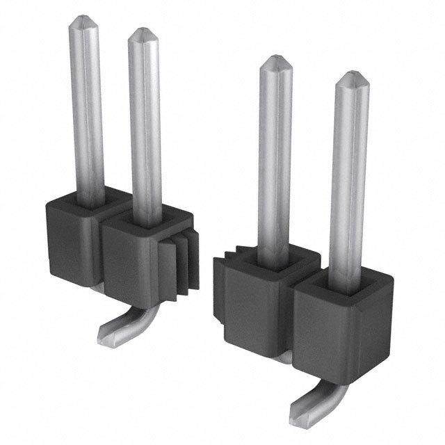
| 产品图片 |
|
| rohs | 符合RoHS无铅 / 符合限制有害物质指令(RoHS)规范要求 |
| 产品系列 | 基本/快动开关,C&K Components TMCGD6SA1040CTM |
| mouser_ship_limit | 该产品可能需要其他文件才能进口到中国。 |
| 数据手册 | http://www.ck-components.com/index.php?module=media&action=Display&cmpref=15153&lang=en&width=&height=&format=&alt= |
| 产品型号 | TMCGD6SA1040C |
| 产品培训模块 | http://www.digikey.cn/PTM/IndividualPTM.page?site=cn&lang=zhs&ptm=30457 |
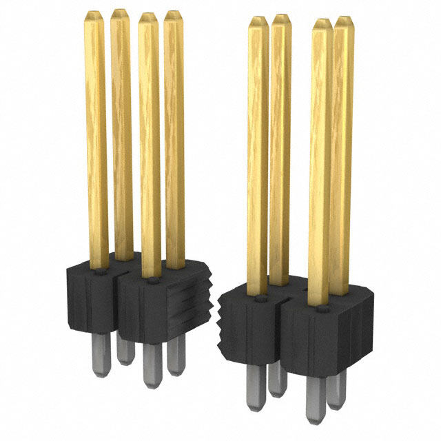
| 产品目录绘图 |
|
| 产品目录页面 | |
| 产品种类 | 基本/快动开关 |
| 侵入防护 | - |
| 其它名称 | *TMCGD6SA1040C |
| 包装 | 散装 |
| 商标 | C&K Components |
| 安装 | Panel |
| 安装类型 | 底座安装 |
| 工作位置 | 0.812" (20.6mm) |
| 工作力 | 0.7 N |
| 工作温度 | -55°C ~ 150°C |
| 工厂包装数量 | 1 |
| 差动行程 | 0.013" (0.33mm) |
| 开关功能 | ON - (OFF), OFF - (ON) |
| 执行器 | Roller Lever |
| 操作力,扭矩 | 90gf |
| 机械寿命 | - |
| 标准包装 | 1 |
| 特性 | - |
| 电压额定值AC | 250 V |
| 电压额定值DC | 250 V |
| 电气寿命 | 350,000 次循环 |
| 电流额定值 | 10 A |
| 电路 | 单刀双掷 |
| 相关产品 | /product-detail/zh/360010-1/A24758-ND/287849/product-detail/zh/0006023031/WM2553-ND/114996 |
| 端子类型 | 快速连接 - 0.187"(4.7mm) |
| 端接类型 | Quick Connect Terminal |
| 类型 | Standard |
| 系列 | TM |
| 致动器类型 | 按片,滚轴 |
| 触点形式 | SPDT |
| 超行程 | 0.035" (0.9mm) |
| 释放力 | 28gf |
| 预行程 | 0.071" (1.8mm) |
| 额定电压-AC | 125V |
| 额定电压-DC | 125V |
| 额定电流 | 10A (AC), 500mA (DC) |


- 商务部:美国ITC正式对集成电路等产品启动337调查
- 曝三星4nm工艺存在良率问题 高通将骁龙8 Gen1或转产台积电
- 太阳诱电将投资9.5亿元在常州建新厂生产MLCC 预计2023年完工
- 英特尔发布欧洲新工厂建设计划 深化IDM 2.0 战略
- 台积电先进制程称霸业界 有大客户加持明年业绩稳了
- 达到5530亿美元!SIA预计今年全球半导体销售额将创下新高
- 英特尔拟将自动驾驶子公司Mobileye上市 估值或超500亿美元
- 三星加码芯片和SET,合并消费电子和移动部门,撤换高东真等 CEO
- 三星电子宣布重大人事变动 还合并消费电子和移动部门
- 海关总署:前11个月进口集成电路产品价值2.52万亿元 增长14.8%


PDF Datasheet 数据手册内容提取
TM Series Miniature Snap-acting Switches Features/Benefits Typical Applications • Broad range of operating forces available • Pumps and motors • Wide variety of actuator and terminal styles • White goods • Cost-effective solution • Consumer appliances Specifications Materials CONTACT RATING: From low level* to 15 AMPS @ 250 V AC. SWITCH HOUSING: Thermoplastic or general purpose phenolic ELECTRICAL LIFE: 150,000 cycles at 15 AMPS @ 250 V AC, models (UL 94V-0). with 150 grams operating force. 350,000 cycles at 10 AMPS @ ACTUATOR BUTTON: Thermoplastic (UL 94V-0). 250 V AC, models with 75 grams operating force. SPRING: Copper alloy. INSULATION RESISTANCE: 1,000 M ohms min. PIVOT: Brass alloy. DIELECTRIC STRENGTH: 1,000 Vrms min. @ sea level. MOVABLE CONTACTS: Gold alloy for ratings 1 AMP @ 125 V AC OPERATING TEMPERATURE: –67ºF to 302ºF (–55ºC to 150ºC). or less. Fine silver for ratings greater than 1 AMP @ 125 V AC. OPERATING FORCE: 50, 75 and 150 grams at actuator available; STATIONARY CONTACTS: Gold alloy for ratings 1 AMP or less. refer to chart for lever style forces. Fine silver for ratings greater than 1 AMP. MOUNTING: Torque screws 2-5 in/lbs. TERMINALS: Brass alloy for ratings up to 10 AMPS @ 250 V AC. Copper alloy for 15 AMPS @ 250 V AC ratings. * Low Level=conditions where no arcing occurs during switching, i.e., 0.4 VA max. @ 20 V AC or DC max. J NOTE: Specifications and materials listed above are for switches with standard options. For information on specific and custom switches, consult Customer Service Center. g n i t c Build-A-Switch a - p To order, simply select desired option from each category and place in the appropriate box. Available options are shown and a described on pages J-26 through J-31. For additional options not shown in catalog, consult Customer Service Center. n S Available extended electrical life per UL 1054, rated for 100,000 operations, consult factory. T M Series TM SP, Mom. Operating Force CG 2.65 oz./75 grams CJ 5.29 oz.,/150 grams CF 1.76 oz./50 grams Mounting Style S Standard Electrical Rating V Metric D6 1O A @ 125 & 250 V AC; 1/3 HP @ 125 & 25O V AC;1/2 A @ 125 V DC; 1/4 A @ 250 V DC Actuator G6 15 A @ 125 & 250 V AC; 1/4 A @ 250 V DC; P00 Pin plunger Terminations 1/2 A @ 125 V DC; 1/2 HP @ 125 & 250 V AC; A10 .81” lever roller, high force 40 .187” quick connect 3 A @ 125 V AC “L” A15 1.34” lever roller, high force 10 Solder F5 1 A @ 125 V AC; 1 A @ 30 V DC A20 1.02” lever roller, low force 4A .250” quick connect H3 5 A @ 250 V AC; 1/6 HP @ 125 & 25O V AC A25 1.56” lever roller, low force 60 Screw T10 .84” lever, high force T13 1.34” simulated roller, high force Circuitry T14 1.29” simulated roller, high force C SPDT T15 1.40” lever, high force W SPST N.C. T16 2.34” lever, high force Y SPST N.O. T17 2.00” lever, high force T18 2.75” lever, high force T20 1.06” lever, low force * All models T23 1.56” simulated roller, low force T24 1.50” simulated roller, low force T25 1.62” lever, low force T26 2.56” lever, low force T27 2.22” lever, low force T28 2.97” lever, low force Dimensions are shown: Inch (mm) Specifications and dimensions subject to change www.ckswitches.com J–26
TM Series Miniature Snap-acting Switches SERIES TM MINIATURE SNAP-ACTING SWITCHES – SP MOMENTARY J OPERATING FORCE S n a BASICSWITCH p OPERATING FORCE - OPTION CODE (OZ./GRAMS) a c CG 27.655 ti n CJ 5.29 g 150 CF 1.76 50 Operating Force option ‘CF’ not available with ‘T18, T27 and T28’ actuator options. Operating force varies with actuator option, see ACTUATOR option section. ELECTRICAL RATING CONTACT MATERIAL RoHS RoHS MOVABLE STATIONARY OPTION CODE COMPLIANT* COMPATIBLE* CONTACT CONTACT ELECTRICAL RATING 10 AMPS @ 125 & 250 V AC; 1/3 HP @ 125 & 250 V AC; 1/2 AMP @ D6 Yes Yes Fine Silver Fine Silver 125 V DC; 1/4 AMP @ 250 V DC. F5 Yes Yes Gold alloy Gold alloy From low level* to 1 AMP @ 125 V AC, 1 AMP @ 30 V DC. 15 AMPS @ 125 & 250 V AC; 0.25 AMP @ 250 V DC; 0.5 AMP @ G6 Yes Yes 125 V DC; 1/2 HP @ 125 & 250 V AC; 3 AMPS @ 125 V AC “L”. Fine Silver Fine Silver H3 Yes Yes 5 AMPS @ 250 V AC; 1/6 HP @ 125 & 250 V AC. * Note: See Technical Data section of this catalog for RoHS compliant and compatible definitions and specifications. * All models * Low Level=conditions where no arcing occurs during switching, i.e., Contact Customer Service Center for availability and delivery of nonstandard ratings. 0.4 VA max. @ 20 V AC or DC max. Dimensions are shown: Inches (mm) Specifications and dimensions subject to change www.ckswitches.com J–27
TM Series Miniature Snap-acting Switches ELECTRICAL RATING AVAILABLE COMBINATIONS MAXIMUM OPERATING FORCE (OZ./GRAMS) ELECTRICAL 1.76/50 2.65/75 5.29/150 RATING CF CG CJ D6 • • • F5 • • • G6 x x • • AVAILABLE H3 • • • x NOT AVAILABLE * All models Contact Customer Service Center for availability and delivery of nonstandard ratings. * Low Level=conditions where no arcing occurs during switching, i.e., 0.4 VA max. @ 20 V AC or DC max. J MOUNTING STYLE g S Standard V Metric n i t c a - p a n S Recommended maximum screw size: 4-40. Recommended maximum screw size: 3 mm. NOTE: Torque mounting screws 2-5 in/lbs. Dimensions are shown: Inch (mm) Specifications and dimensions subject to change www.ckswitches.com J–28
TM Series Miniature Snap-acting Switches ACTUATOR A D OPTION CODE FIG. DIM. A DIM. B DIM. C DIM. D B A P00 2 .80 — .578 ±.015 — (20,3) (14,68 ±0,38) A10 1 .81 .36 .810 ±.020 .19 dia. C (20,6) (9,1) (20,57 ±0,51) (4,8Ø) C A15 1 1.34 .36 .810 ±.040 .19 dia. (34,0) (9,1) (20,57 ±1,02) (4,8Ø) A20 1 1.03 .58 .810 ±.050 .19 dia. (26,2) (14,7) (20,57 ±1,27) (4,8Ø) A25 1 (13.95,66) (1.548,7) (2.801,507 ±±.20,8003) .1(49, 8dØia). FIG. 1 FIG. 2 Lever Roller Pin Roller T10 3 .84 .36 .600 ±.020 — (21,3) (9,1) (15,24 ±0,51) A T13 4 1.34 .36 .810 ±.040 .19 dia. B (34,0) (9,1) (20,57 ±1,02) (4,8Ø) T14 4 1.28 .36 .743 ±.050 .236 dia. (32,5) (9,1) (18,9 ±1,3) (6,0Ø) T15 3 1.40 .36 .600 ±.040 — C (35,6) (9,1) (15,24 ±1,02) T16 3 2.34 .36 .600 ±.062 — (59,4) (9,1) (15,24 ±1,57) T17 3 2.00 .36 .600 ±.052 — (50,8) (9,1) (15,24 ±1,57) FIG. 3 J T18 3 2.75 .36 .600 ±.093 — Lever (69,9) (9,1) (15,24 ±2,36) T20 3 (12.60,69) (1.548,7) (1.650,204 ±±.014,154) — S n T23 4 (13.95,66) (1.548,7) (2.801,507 ±±.016,655) .1(49, 8dØia). A D a p T24 4 1.50 .58 .743 ±.090 .236 dia. B - (38,1) (14,7) (18,80 ±2,29) (6,0Ø) a T25 3 (14.16,21) (1.548,7) (1.650,204 ±±.20,8003) — C cti n T26 3 (26.55,60) (1.546,7) (1.650,204±±.132.158) — g T27 3 (25.62,24) (1.548,7) (1.650,204±±.132.158) — T28 3 (27.59,74) (1.548,7) (1.650,204±±.148.775) — FIG. 4 Simulated Roller HIGH FORCE, LOW MOTION PIVOT POSITION LOW FORCE, HIGH MOTION PIVOT POSITION Available with actuators A10, A15, T10, T13, T14, T15, T16, T17 and T18. Available with actuators A20, A25, T20, T23, T24, T25, T26, T 27 and T28. NOTE: Lever actuator options are available in either of two pivot positions. Levers located in the forward pivot position have lower forces and higher motions. Levers located in the rear pivot position have higher forces and lower motions. Dimensions are shown: Inches (mm) Specifications and dimensions subject to change www.ckswitches.com J–29
TM Series Miniature Snap-acting Switches ACTUATOR SWITCHCHARACTERISTICS MAXIMUM OPERATING FORCE MINIMUM RELEASE MINIMUM RETURN FORCE MAXIMUM (OZ./GRAMS) FORCE (OZ./GRAMS) (OZ./GRAMS) DIFFERENTIAL MAXIMUM MINIMUM TRAVEL PRETRAVEL OVERTRAVEL OPTION CODE C(5F0) (C75G) (1C5J0) C(5F0) (C75G) (1C5J0) C(5F0) (C75G) (1C5J0) ALLFORCES ALLFORCES ALLFORCES 2.12 3.17 6.35 .49 .99 1.69 .25 .53 1.06 .013 .080 .035 T10 60 90 180 14 28 48 7 15 30 (0,33) (2,03) (0,89) 1.06 1.59 2.82 .21 .35 .71 .11 .14 .35 .030 .160 .065 T13 30 45 80 6 10 20 3 4 10 (0,76) (4,06) (1,65) 1.06 1.76 3.17 .25 .35 .71 .11 .14 .35 .050 .140 .062 T13 30 50 90 7 10 20 3 4 10 (1,27) (3,56) (1,57) 1.06 1.59 2.28 .21 .32 .71 .11 .14 .35 .032 .160 .075 T15 30 45 80 6 9 20 3 4 10 (0,81) (4,06) (1,90) .53 .71 1.41 .11 .18 .35 .05 .07 .18 .090 .312 .140 T16 15 20 40 3 5 10 1.5 2 5 (2,29) (7,92) (3,56) .71 .88 1.76 .14 .21 .42 .07 .07 .21 .062 .220 .110 T17 20 25 50 4 6 12 2 2 6 (1,57) (5,59) (2,79) .71 1.23 .14 .28 .04 .14 .078 .375 .160 T18 N/A N/A N/A 20 35 4 8 1 4 (1,98) (9,52) (4,06) 1.06 1.59 3.17 .21 .32 .71 .11 .18 .35 .030 .160 .065 T20 30 45 90 6 9 20 3 5 10 (0,76) (4,06) (1,65) .53 1.06 1.59 .11 .18 .35 .04 .07 .18 .070 .312 .125 T23 15 30 45 3 5 10 1 2 5 (1,78) (7,92) (3,18) J .53 1.23 1.76 .11 .18 .35 .05 .07 .18 .080 .312 .110 T24 15 35 50 3 5 10 1.5 2 5 (2,03) (7,92) (2,79) g .71 1.06 1.41 .07 .14 .32 .04 .07 .16 .070 .330 .100 n T25 20 30 40 2 4 9 1 2 4.5 (1,78) (8,38) (2,54) i t ac T26 N/A .1305 .2701 N/A .027 .158 N/A .014 .027 (.21,1709) (.1520,07) (.62,5305) - p T27 N/A .60 .88 N/A .11 .21 N/A .04 .11 .125 .500 .200 a 17 25 3 6 1 3 (3,18) (12,70) (5,08) n .42 .63 .07 .14 .04 .07 .187 .750 .280 S T28 N/A N/A N/A 12 18 2 4 1 2 (4,75) (19,05) (7,11) 2.12 3.17 6.35 .49 .99 1.69 .25 .53 1.06 .013 .070 .035 A10 60 90 180 14 28 48 7 15 30 (0,33) (1,78) (0,89) 1.06 1.59 2.82 .21 .35 .71 .11 .14 .35 .030 .160 .065 A15 30 45 80 6 10 20 3 4 10 (0,76) (4,06) (1,65) 1.06 1.76 3.17 .25 .35 .71 .11 .18 .35 .025 .140 .060 A20 30 50 90 7 10 20 3 5 10 (0,64) (3,56) (1,52) .53 1.06 1.59 .11 .18 .35 .04 .07 .18 .070 .312 .125 A25 15 30 45 3 5 10 1 2 5 (1,78) (7,92) (3,18) 1.76 2.65 5.29 .71 .99 2.12 .35 .53 1.06 .013 .056 .035 P00 50 75 150 20 28 60 10 15 30 (0,33) (1,42) (0,89) NOTE:For basic switch operating forces, see page J-26. Dimensions are shown: Inch (mm) Specifications and dimensions subject to change www.ckswitches.com J–30
TM Series Miniature Snap-acting Switches TERMINATIONS 40 60 .187” QUICK CONNECT SCREW TERMINALS Torque screws to 6 in. lbs max. Not available with ‘F5’ rating option. 10 4A SOLDER .250” QUICK CONNECT J S n a p - a c t i n g Not available with ‘F5’ rating option. Not available with ‘F5’ rating option. CIRCUITRY C SPDT (Single Pole, Double Throw) W SPST N.C. (Single Pole, Single Throw, Normally Closed) Y SPST N.O. (Single Pole, Single Throw, Normally Open) Dimensions are shown: Inches (mm) Specifications and dimensions subject to change www.ckswitches.com J–31
Mouser Electronics Authorized Distributor Click to View Pricing, Inventory, Delivery & Lifecycle Information: C &K Switches: TMCGD6ST1840C TMCGD6ST2740C TMCGD6SA1540C TMCGD6ST1440C TMCGD6SA1040C TMCGD6SP004AC TMCGD6ST1540C TMCGD6SP0040W TMCGD6SP0040Y TMCGF5VP0040C TMCGD6SP0040C TMCJG6SP0040C TMCGD6SA1010C TMCGD6SA154AC TMCGD6ST174AC TMCGF5SP0040C TMCJD6ST1410Y TMCJG6SA2540C TMCJG6ST1040C TMCJG6ST1540C TMCJG6VT1640Y TMCJG6VT2810C TMCFD6SP0040W TMCGF5ST1040C TMCGD6ST2040C TMCGD6ST1040C TMCGD6SA2040C TMCJF5SP0040W TMCGF5SA1040C TMCFD6ST2510C TMCGF5SA2540C TMCGD6ST1540Y TMCJG6ST1440C TMCJG6SA1040C TMCJG6ST1540Y TMCGF5ST1540Y TMCJG6SA1010C TMCFF5ST1440C TMCFD6SA1040C TMCJG6SP004AC TMCGF5ST1440C TMCJG6SA1040W TMCJD6SA1540C TMCJG6ST2440W TMCJF5ST1540C TMCGD6VP004AC TMCJD6ST1640Y TMCFD6SA2040C TMCJD6ST1540C TMCJG6ST1840Y TMCJD6SP0040C TMCFD6ST1040C TMCFD6SP0040Y TMCJG6VP0040Y TMCGD6SP004AY TMCJG6ST1560C TMCJD6VP0040C TMCFH3ST204AC TMCJH3SP0040W TMCGD6VT1410C TMCJG6ST1340C TMCGF5VT2440C TMCJD6VP0010C TMCGD6ST1640C TMCGH3ST1640C TMCJF5SP0040C TMCJG6ST1010C TMCGD6VA1040Y TMCJG6SA1540W TMCGF5SA1540C TMCGD6ST2440C TMCFF5SP0040Y TMCJH3SP0040Y TMCGD6VT2040Y TMCGD6VT1040Y TMCGD6SA104AC TMCJG6ST1510C TMCGF5ST1740Y TMCGD6SA2510Y TMCFD6ST1540C TMCGD6ST154AC TMCJG6ST2540Y TMCJG6VA1540C TMCGD6ST2540C TMCJG6SP0040W TMCFF5ST1540C TMCJG6SA1540C TMCJF5ST1440C TMCJD6ST2840C TMCGD6ST254AC TMCJG6ST1040W TMCFD6SP0040C TMCJG6SA1040Y TMCGD6ST1340C TMCGF5SP0040Y TMCGD6SA2540C TMCGD6ST2340C TMCFF5SA2040Y TMCJD6ST1440C TMCJG6VT2010C