ICGOO在线商城 > 集成电路(IC) > 接口 - 驱动器,接收器,收发器 > TJA1040T/CM,118
- 型号: TJA1040T/CM,118
- 制造商: NXP Semiconductors
- 库位|库存: xxxx|xxxx
- 要求:
| 数量阶梯 | 香港交货 | 国内含税 |
| +xxxx | $xxxx | ¥xxxx |
查看当月历史价格
查看今年历史价格
TJA1040T/CM,118产品简介:
ICGOO电子元器件商城为您提供TJA1040T/CM,118由NXP Semiconductors设计生产,在icgoo商城现货销售,并且可以通过原厂、代理商等渠道进行代购。 TJA1040T/CM,118价格参考¥7.30-¥9.12。NXP SemiconductorsTJA1040T/CM,118封装/规格:接口 - 驱动器,接收器,收发器, 1/1 Transceiver Half CANbus 8-SO。您可以下载TJA1040T/CM,118参考资料、Datasheet数据手册功能说明书,资料中有TJA1040T/CM,118 详细功能的应用电路图电压和使用方法及教程。
NXP USA Inc. 的 TJA1040T/CM,118 是一款高速 CAN(控制器局域网)收发器,属于接口类驱动器/接收器/收发器产品,广泛应用于汽车和工业领域。该器件作为CAN协议控制器与物理总线之间的接口,支持高达1 Mbps的通信速率,具备低电磁辐射和高抗干扰能力,符合ISO 11898-2标准。

其主要应用场景包括汽车电子系统,如发动机控制单元(ECU)、车身电子模块(如车门控制、灯光系统)、变速器控制、防抱死制动系统(ABS)和安全气囊系统等。由于TJA1040T/CM集成了静音模式(Silent Mode)和待机功能,有助于降低功耗,适合对能效和稳定性要求较高的车载网络环境。

此外,该收发器也适用于工业自动化控制系统,如PLC(可编程逻辑控制器)、电机驱动器和远程I/O模块,用于实现设备间的可靠实时通信。其工作温度范围宽(-40°C 至 +125°C),耐受恶劣环境能力强,适合在高温、振动等严苛条件下稳定运行。

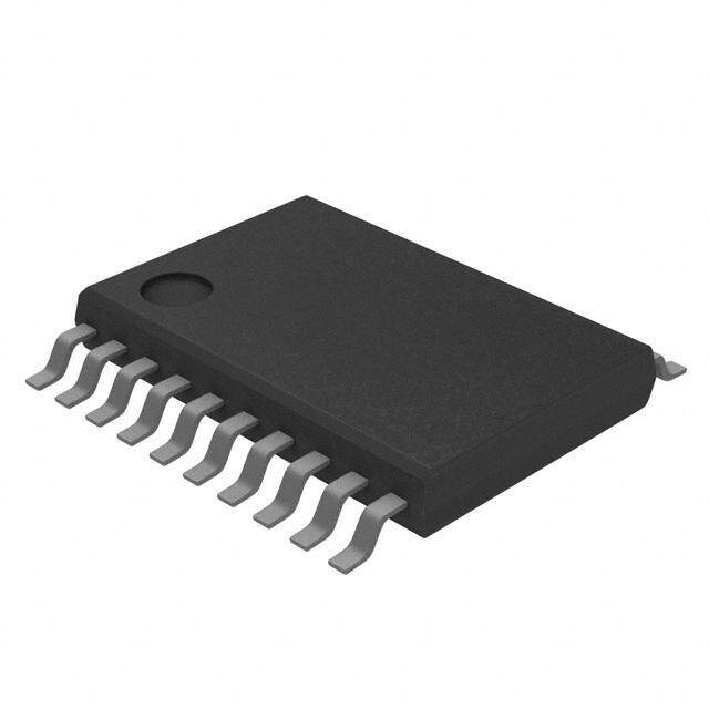
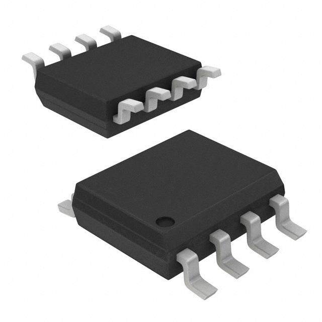
TJA1040T/CM,118采用SOIC8封装,便于PCB布局和自动化生产,是CAN总线网络中实现可靠数据传输的关键组件。
| 参数 | 数值 |
| 产品目录 | 集成电路 (IC)半导体 |
| 描述 | IC TRANSCEIVER CAN 8SOICCAN 接口集成电路 |
| 产品分类 | |
| 品牌 | NXP Semiconductors |
| 产品手册 | |
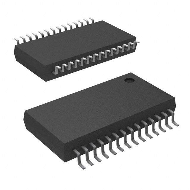
| 产品图片 |
|
| rohs | 符合RoHS无铅 / 符合限制有害物质指令(RoHS)规范要求 |
| 产品系列 | 接口 IC,CAN 接口集成电路,NXP Semiconductors TJA1040T/CM,118- |
| 数据手册 | |
| 产品型号 | TJA1040T/CM,118 |
| PCN封装 | |
| PCN过时产品 | |
| 产品培训模块 | http://www.digikey.cn/PTM/IndividualPTM.page?site=cn&lang=zhs&ptm=8831 |
| 产品种类 | CAN 接口集成电路 |
| 供应商器件封装 | 8-SO |
| 其它名称 | 568-10289-6 |
| 包装 | Digi-Reel® |
| 协议 | CAN |
| 双工 | 半 |
| 商标 | NXP Semiconductors |
| 安装类型 | 表面贴装 |
| 封装 | Reel |
| 封装/外壳 | 8-SOIC(0.154",3.90mm 宽) |
| 工作温度 | - |
| 工厂包装数量 | 2500 |
| 接收器滞后 | 70mV |
| 数据速率 | - |
| 标准包装 | 1 |
| 电压-电源 | 4.75 V ~ 5.25 V |
| 类型 | 收发器 |
| 驱动器/接收器数 | 1/1 |






- 商务部:美国ITC正式对集成电路等产品启动337调查
- 曝三星4nm工艺存在良率问题 高通将骁龙8 Gen1或转产台积电
- 太阳诱电将投资9.5亿元在常州建新厂生产MLCC 预计2023年完工
- 英特尔发布欧洲新工厂建设计划 深化IDM 2.0 战略
- 台积电先进制程称霸业界 有大客户加持明年业绩稳了
- 达到5530亿美元!SIA预计今年全球半导体销售额将创下新高
- 英特尔拟将自动驾驶子公司Mobileye上市 估值或超500亿美元
- 三星加码芯片和SET,合并消费电子和移动部门,撤换高东真等 CEO
- 三星电子宣布重大人事变动 还合并消费电子和移动部门
- 海关总署:前11个月进口集成电路产品价值2.52万亿元 增长14.8%




PDF Datasheet 数据手册内容提取
INTEGRATED CIRCUITS DATA SHEET TJA1040 High speed CAN transceiver Product specification 2003 Oct 14 Supersedes data of 2003 Feb 19
Philips Semiconductors Product specification High speed CAN transceiver TJA1040 FEATURES GENERAL DESCRIPTION • Fully compatible with the ISO11898 standard TheTJA1040istheinterfacebetweentheControllerArea • High speed (up to 1MBaud) Network(CAN) protocol controller and the physical bus. Itis primarily intended for high speed applications, up to • Very low-current standby mode with remote wake-up 1MBaud, in passenger cars. The device provides capability via the bus differential transmit capability to the bus and differential • Very low ElectroMagnetic Emission (EME) receive capability to the CAN controller. • Differential receiver with high common-mode range for The TJA1040 is the next step up from the TJA1050 high ElectroMagnetic Immunity (EMI) speedCANtransceiver.Beingpincompatibleandoffering • Transceiver in unpowered state disengages from the the same excellent EMC performance, the TJA1040 also bus (zero load) features: • Input levels compatible with 3.3V and 5V devices • An ideal passive behaviour when supply voltage is off • Voltage source for stabilizing the recessive bus level if • A very low-current standby mode with remote wake-up split termination is used (further improvement of EME) capability via the bus. • At least 110nodes can be connected This makes the TJA1040 an excellent choice in nodes • Transmit Data(TXD) dominant time-out function which can be in power-down or standby mode in partially • Bus pins protected against transients in automotive powered networks. environments • BuspinsandpinSPLITshort-circuitprooftobatteryand ground • Thermally protected. QUICK REFERENCE DATA SYMBOL PARAMETER CONDITIONS MIN. MAX. UNIT V supply voltage operating range 4.75 5.25 V CC I supply current standby mode 5 15 m A CC V DCvoltage on pinCANH 0<V <5.25V; no time limit - 27 +40 V CANH CC V DCvoltage on pinCANL 0<V <5.25V; no time limit - 27 +40 V CANL CC V DCvoltage on pinSPLIT 0<V <5.25V; no time limit - 27 +40 V SPLIT CC V electrostatic discharge voltage Human Body Model(HBM) esd pins CANH, CANL andSPLIT - 6 +6 kV all other pins - 4 +4 kV t propagation delay TXDtoRXD V =0V 40 255 ns PD(TXD-RXD) STB T virtual junction temperature - 40 +150 (cid:176) C vj ORDERING INFORMATION PACKAGE TYPE NUMBER NAME DESCRIPTION VERSION TJA1040T SO8 plastic small outline package; 8leads; body width 3.9mm SOT96-1 TJA1040U - bare die; die dimensions 1840· 1440· 380m m - 2003Oct14 2
Philips Semiconductors Product specification High speed CAN transceiver TJA1040 BLOCK DIAGRAM handbook, full pagewidth VCC 3 5 TXD 1 TIME-OUT & TEMPERATURE V SPLIT SPLIT SLOPE PROTECTION VCC 7 CANH 6 CANL STB 8 WAKE-UP DRIVER MODE CONTROL 4 WAKE-UP RXD MUX FILTER TJA1040 2 GND MGU161 Fig.1 Block diagram. PINNING SYMBOL PIN DESCRIPTION TXD 1 transmit data input handbook, halfpage GND 2 ground supply TXD 1 8 STB VCC 3 supply voltage GND 2 7 CANH TJA1040T RXD 4 receive data output; reads out data VCC 3 6 CANL from the bus lines RXD 4 5 SPLIT SPLIT 5 common-mode stabilization output MGU160 CANL 6 LOW-level CAN bus line CANH 7 HIGH-level CAN bus line Fig.2 Pin configuration. STB 8 standby mode control input 2003Oct14 3
Philips Semiconductors Product specification High speed CAN transceiver TJA1040 FUNCTIONAL DESCRIPTION tothecentretapofthesplittermination(seeFig.4).Incase ofarecessivebusvoltage<0.5V duetothepresenceof Operating modes CC anunsuppliedtransceiverinthenetworkwithasignificant TheTJA1040providestwomodesofoperationwhichare leakage current from the bus lines to ground, the split selectableviapinSTB.SeeTable1foradescriptionofthe circuit will stabilize this recessive voltage to 0.5V . So a CC modes of operation. start of transmission does not cause a step in the common-mode signal which would lead to poor Table 1 Operating modes ElectroMagnetic Emission(EME) behaviour. PINRXD PIN Wake-up MODE STB LOW HIGH In the standby mode the bus lines are monitored via a normal LOW bus dominant bus recessive low-power differential comparator. Once the low-power standby HIGH wake-uprequest no wake-up differentialcomparatorhasdetectedadominantbuslevel detected request detected for more than tBUS, pinRXD will become LOW. Over-temperature detection NORMALMODE Theoutputdriversareprotectedagainstover-temperature Inthismodethetransceiverisabletotransmitandreceive conditions.Ifthevirtualjunctiontemperatureexceedsthe dataviathebuslinesCANHandCANL.SeeFig.1forthe shutdownjunctiontemperatureT ,theoutputdriverswill block diagram. The differential receiver converts the j(sd) bedisableduntilthevirtualjunctiontemperaturebecomes analog data on the bus lines into digital data which is lower than T and TXD becomes recessive again. outputtopinRXDviathemultiplexer(MUX).Theslopeof j(sd) Byincluding the TXDcondition, the occurrence of output the output signals on the bus lines is fixed and optimized driver oscillation due to temperature drifts is avoided. in a way that lowest ElectroMagnetic Emission (EME) is guaranteed. TXD dominant time-out function STANDBYMODE A ‘TXD dominant time-out’ timer circuit prevents the bus lines from being driven to a permanent dominant state Inthismodethetransmitterandreceiverareswitchedoff, (blocking all network communication) if pinTXD is forced andthelow-powerdifferentialreceiverwillmonitorthebus permanently LOW by a hardware and/or software lines. A HIGH level on pinSTB activates this low-power application failure. The timer is triggered by a negative receiver and the wake-up filter, and after t the state of BUS edge on pinTXD. the CAN bus is reflected on pinRXD. If the duration of the LOW level on pinTXD exceeds the The supply current onV is reduced to a minimum in CC internal timer value (t ), the transmitter is disabled, such a way that ElectroMagnetic Immunity(EMI) is dom driving the bus lines into a recessive state. The timer is guaranteed and a wake-up event on the bus lines will be reset by a positive edge on pinTXD. TheTXD dominant recognized. time-outtimet definestheminimumpossiblebitrateof dom In this mode the bus lines are terminated to ground to 40kBaud. reduce the supply current (I ) to a minimum. A diode is CC addedinserieswiththehigh-sidedriverofRXDtoprevent Fail-safe features areversecurrentfromRXDtoV intheunpoweredstate. CC PinTXDprovidesapull-uptowardsV inordertoforcea In normal mode this diode is bypassed. This diode is not CC recessive level in case pinTXD is unsupplied. bypassedinstandbymodetoreducecurrentconsumption. PinSTB provides a pull-up towards V in order to force CC Split circuit the transceiver into standby mode in case pinSTB is unsupplied. PinSPLITprovidesaDCstabilizedvoltageof0.5V .Itis CC turnedononlyinnormalmode.InstandbymodepinSPLIT In the event that the V is lost, pinsTXD, STB andRXD CC is floating. The VSPLIT circuit can be used to stabilize the will become floating to prevent reverse supplying recessivecommon-modevoltagebyconnectingpinSPLIT conditions via these pins. 2003Oct14 4
Philips Semiconductors Product specification High speed CAN transceiver TJA1040 LIMITING VALUES In accordance with the Absolute Maximum Rating System (IEC60134). SYMBOL PARAMETER CONDITIONS MIN. MAX. UNIT V supply voltage no time limit - 0.3 +6 V CC operating range 4.75 5.25 V V DCvoltage on pinTXD - 0.3 V +0.3 V TXD CC V DCvoltage on pinRXD - 0.3 V +0.3 V RXD CC V DCvoltage on pinsSTB - 0.3 V +0.3 V STB CC V DCvoltage on pinCANH 0<V <5.25V; no time limit - 27 +40 V CANH CC V DCvoltage on pinCANL 0<V <5.25V; no time limit - 27 +40 V CANL CC V DCvoltage on pinSPLIT 0<V <5.25V; no time limit - 27 +40 V SPLIT CC V transient voltages on pinsCANH, according to ISO7637; seeFig.5 - 200 +200 V trt CANL andSPLIT V electrostatic discharge voltage HumanBodyModel(HBM);note1 esd pinsCANH andCANL - 6 +6 kV andSPLIT all other pins - 4 +4 kV Machine Model(MM); note2 - 200 +200 V T virtual junction temperature note3 - 40 +150 (cid:176) C vj T storage temperature - 55 +150 (cid:176) C stg Notes 1. Equivalent to discharging a 100pF capacitor via a 1.5kW series resistor. 2. Equivalent to discharging a 200pF capacitor via a 0.75m H series inductor and a 10W series resistor. 3. JunctiontemperatureinaccordancewithIEC60747-1.AnalternativedefinitionofT is:T =T +P· R , vj vj amb th(vj-amb) where R is a fixed value to be used for the calculating of T . The rating for T limits the allowable th(vj-amb) vj vj combinations of power dissipation (P) and ambient temperature (T ). amb THERMAL CHARACTERISTICS In accordance with IEC60747-1. SYMBOL PARAMETER CONDITIONS VALUE UNIT R thermal resistance from virtual junction in free air 145 K/W th(vj-a) to ambient in SO8 package R thermal resistance from virtual junction in free air 50 K/W th(vj-s) to substrate of bare die QUALITY SPECIFICATION Quality specification in accordance with“AEC-Q100”. 2003Oct14 5
Philips Semiconductors Product specification High speed CAN transceiver TJA1040 CHARACTERISTICS V =4.75to5.25V, T =- 40to+150(cid:176) C and R =60W unless specified otherwise; all voltages are defined with CC vj L respect to ground; positive currents flow into theIC; note1. SYMBOL PARAMETER CONDITIONS MIN. TYP. MAX. UNIT Supply (pinV ) CC I supply current standby mode 5 10 15 m A CC normal mode recessive; V =V 2.5 5 10 mA TXD CC dominant; V =0V 30 50 70 mA TXD Transmit data input (pinTXD) V HIGH-level input voltage 2 - V +0.3 V IH CC V LOW-level input voltage - 0.3 - +0.8 V IL I HIGH-level input current V =V - 5 0 +5 m A IH TXD CC I LOW-level input current normal mode; V =0V - 100 - 200 - 300 m A IL TXD C input capacitance not tested - 5 10 pF i Standby mode control input (pinSTB) V HIGH-level input voltage 2 - V +0.3 V IH CC V LOW-level input voltage - 0.3 - +0.8 V IL I HIGH-level input current V =V - 0 - m A IH STB CC I LOW-level input current V =0V - 1 - 4 - 10 m A IL STB Receive data output (pinRXD) V HIGH-level output voltage standby mode; V - 1.1 V - 0.7 V - 0.4 V OH CC CC CC I =- 100m A RXD I HIGH-level output current normal mode; - 0.1 - 0.4 - 1 mA OH V =V - 0.4V RXD CC I LOW-level output current V =0.4V 2 6 12 mA OL RXD Common-mode stabilization output (pinSPLIT) V output voltage normal mode; 0.3V 0.5V 0.7V V O CC CC CC - 500m A<I <+500m A O (cid:239) I (cid:239) leakage current standby mode; - 0 5 m A L - 22V<V <+35V SPLIT Bus lines (pinsCANH andCANL) V dominant output voltage V =0V O(dom) TXD pinCANH 3 3.6 4.25 V pinCANL 0.5 1.4 1.75 V V matching of dominant output - 100 0 +150 mV O(dom)(m) voltage (V -V -V ) CC CANH CANL V differential bus output voltage V =0V; dominant; 1.5 - 3.0 V O(dif)(bus) TXD (V - V ) 45W <R <65W CANH CANL L V =V ; recessive; - 50 - +50 mV TXD CC noload 2003Oct14 6
Philips Semiconductors Product specification High speed CAN transceiver TJA1040 SYMBOL PARAMETER CONDITIONS MIN. TYP. MAX. UNIT V recessive output voltage normalmode;V =V ; 2 0.5V 3 V O(reces) TXD CC CC noload standby mode; no load - 0.1 0 +0.1 V I short-circuit output current V =0V O(sc) TXD pinCANH; V =0V - 40 - 70 - 95 mA CANH pinCANL; V =40V 40 70 100 mA CANL I recessive output current - 27V<V <+32V - 2.5 - +2.5 mA O(reces) CAN V differential receiver threshold - 12V<V <+12V; dif(th) CANL voltage - 12V<V <+12V CANH normalmode(seeFig.6) 0.5 0.7 0.9 V standby mode 0.4 0.7 1.15 V V differential receiver hysteresis normal mode; 50 70 100 mV hys(dif) voltage - 12V<V <+12V; CANL - 12V<V <+12V CANH I input leakage current V =0V; - 5 0 +5 m A LI CC V =V =5V CANH CANL R common-mode input standby or normal mode 15 25 35 kW i(cm) resistance R common-mode input V =V - 3 0 +3 % i(cm)(m) CANH CANL resistance matching R differential input resistance standby or normal mode 25 50 75 kW i(dif) C common-mode input V =V ; not tested - - 20 pF i(cm) TXD CC capacitance C differential input capacitance V =V ; not tested - - 10 pF i(dif) TXD CC Timing characteristics;seeFig.8 t delay TXD to bus active normal mode 25 70 110 ns d(TXD-BUSon) t delay TXD to bus inactive 10 50 95 ns d(TXD-BUSoff) t delay bus active to RXD 15 65 115 ns d(BUSon-RXD) t delay bus inactive to RXD 35 100 160 ns d(BUSoff-RXD) t propagationdelayTXDtoRXD V =0V 40 - 255 ns PD(TXD-RXD) STB t TXD dominant time-out V =0V 300 600 1000 m s dom(TXD) TXD t dominant time for wake-up via standby mode 0.75 1.75 5 m s BUS bus t delaystandbymodetonormal normal mode 5 7.5 10 m s d(stb-norm) mode Thermal shutdown T shutdownjunctiontemperature 155 165 180 (cid:176) C j(sd) Note 1. Allparametersareguaranteedoverthevirtualjunctiontemperaturerangebydesign,butonly100%testedat125(cid:176) C ambient temperature for dies on wafer level, and in addition to this 100% tested at 25(cid:176) C ambient temperature for casedproducts;unlessspecifiedotherwise.Forbaredies,allparametersareonlyguaranteedwiththebacksideof the die connected to ground. 2003Oct14 7
Philips Semiconductors Product specification High speed CAN transceiver TJA1040 APPLICATION AND TEST INFORMATION handbook, full pagewidth BAT 5 V VCC CANH 3 STB VCC 7 8 Port x TJA1040 SPLIT MICROCONTROLLER 5 RXD 4 RXD CANL TXD 6 1 TXD 2 MGU164 Moreapplicationinformationisavailableinaseparateapplicationnote. Fig.3 Typical application for 5V microcontroller. handbook, full pagewidth VCC TJA1040 CANH R 60 W VSPLIT = 0.5VCC SPLIT in normal mode; otherwise floating R 60 W CANL MGU162 GND Fig.4 Stabilization circuitry and application. 2003Oct14 8
Philips Semiconductors Product specification High speed CAN transceiver TJA1040 handbook, full pagewidth +5 V 47 m F 100 nF VCC 3 1 nF TXD CANH 1 7 TRANSIENT 1 nF GENERATOR CANL 500 kHz TJA1040 6 SPLIT RXD 5 4 2 8 15 pF GND STB MGW336 The waveforms of the applied transients will be in accordance with ISO7637 part1, test pulses1, 2, 3a, 3b, 5, 6 and7. Fig.5 Test circuit for automotive transients. handbook, full pagewidth MGS378 VRXD HIGH LOW hysteresis 0.5 0.9 Vi(dif)(bus) (V) Fig.6 Hysteresis of the receiver. 2003Oct14 9
Philips Semiconductors Product specification High speed CAN transceiver TJA1040 handbook, full pagewidth +5 V 47 m F 100 nF VCC 3 TXD 1 CANH 7 SPLIT 5 TJA1040 RL CL 60 W 100 pF CANL RXD 6 4 2 8 15 pF GND STB MGW335 Fig.7 Test circuit for timing characteristics. HIGH handbook, full pagewidth TXD LOW CANH CANL dominant (BUS on) 0.9 V Vi(dif)(bus)(1) 0.5 V recessive (BUS off) HIGH RXD 0.3VCC 0.7VCC LOW td(TXD-BUSon) td(TXD-BUSoff) td(BUSon-RXD) td(BUSoff-RXD) tPD(TXD-RXD) tPD(TXD-RXD) MGS377 (1) Vi(dif)(bus)=VCANH- VCANL. Fig.8 Timing diagram. 2003Oct14 10
Philips Semiconductors Product specification High speed CAN transceiver TJA1040 BONDING PAD LOCATIONS COORDINATES(1) SYMBOL PAD x y handbook, halfpage 8 7 6 5 TXD 1 119.5 114.5 GND 2 648.5 85 test pad 1 V 3 1214.25 114.5 CC TJA1040U RXD 4 1635.25 114.5 test pad 2 SPLIT 5 1516.5 1275 CANL 6 990.5 1273.75 x CANH 7 530.25 1273.75 0 1 2 3 4 0 STB 8 113.75 1246 y MBL584 Note The backside of the bare die must be connected to ground. 1. Allx/ycoordinatesrepresentthepositionofthecentre of each pad (inm m) with respect to the left hand Fig.9 Bonding pad locations. bottom corner of the top aluminium layer (see Fig.9). 2003Oct14 11
Philips Semiconductors Product specification High speed CAN transceiver TJA1040 PACKAGE OUTLINE SO8: plastic small outline package; 8 leads; body width 3.9 mm SOT96-1 D E A X c y HE v M A Z 8 5 Q A2 A1 (A 3 ) A pin 1 index q Lp 1 4 L e w M detail X bp 0 2.5 5 mm scale DIMENSIONS (inch dimensions are derived from the original mm dimensions) UNIT mAax. A1 A2 A3 bp c D(1) E(2) e HE L Lp Q v w y Z(1) q 0.25 1.45 0.49 0.25 5.0 4.0 6.2 1.0 0.7 0.7 mm 1.75 0.25 1.27 1.05 0.25 0.25 0.1 0.10 1.25 0.36 0.19 4.8 3.8 5.8 0.4 0.6 0.3 8o 0.010 0.057 0.019 0.0100 0.20 0.16 0.244 0.039 0.028 0.028 0o inches 0.069 0.01 0.05 0.041 0.01 0.01 0.004 0.004 0.049 0.014 0.0075 0.19 0.15 0.228 0.016 0.024 0.012 Notes 1. Plastic or metal protrusions of 0.15 mm (0.006 inch) maximum per side are not included. 2. Plastic or metal protrusions of 0.25 mm (0.01 inch) maximum per side are not included. OUTLINE REFERENCES EUROPEAN ISSUE DATE VERSION PROJECTION IEC JEDEC JEITA 99-12-27 SOT96-1 076E03 MS-012 03-02-18 2003Oct14 12
Philips Semiconductors Product specification High speed CAN transceiver TJA1040 SOLDERING To overcome these problems the double-wave soldering method was specifically developed. Introduction to soldering surface mount packages Ifwavesolderingisusedthefollowingconditionsmustbe Thistextgivesaverybriefinsighttoacomplextechnology. observed for optimal results: Amorein-depthaccountofsolderingICscanbefoundin our“Data Handbook IC26; Integrated Circuit Packages” • Use a double-wave soldering method comprising a (document order number 939865290011). turbulentwavewithhighupwardpressurefollowedbya smooth laminar wave. There is no soldering method that is ideal for all surface • For packages with leads on two sides and a pitch (e): mount IC packages. Wave soldering can still be used for certainsurfacemountICs,butitisnotsuitableforfinepitch – larger than or equal to 1.27mm, the footprint SMDs. In these situations reflow soldering is longitudinal axis ispreferred to be parallel to the recommended. transport direction of the printed-circuit board; – smaller than 1.27mm, the footprint longitudinal axis Reflow soldering must be parallel to the transport direction of the printed-circuit board. Reflow soldering requires solder paste (a suspension of finesolderparticles,fluxandbindingagent)tobeapplied The footprint must incorporate solder thieves at the totheprinted-circuitboardbyscreenprinting,stencillingor downstream end. pressure-syringe dispensing before package placement. • Forpackageswithleadsonfoursides,thefootprintmust Driven by legislation and environmental forces the beplacedata45(cid:176) angletothetransportdirectionofthe worldwide use of lead-free solder pastes is increasing. printed-circuit board. The footprint must incorporate Several methods exist for reflowing; for example, solder thieves downstream and at the side corners. convection or convection/infrared heating in a conveyor Duringplacementandbeforesoldering,thepackagemust type oven. Throughput times (preheating, soldering and be fixed with a droplet of adhesive. The adhesive can be cooling) vary between 100and200seconds depending applied by screen printing, pin transfer or syringe on heating method. dispensing. The package can be soldered after the Typical reflow peak temperatures range from adhesive is cured. 215to270(cid:176) C depending on solder paste material. The Typical dwell time of the leads in the wave ranges from top-surface temperature of the packages should 3to4seconds at 250(cid:176) C or 265(cid:176) C, depending on solder preferably be kept: material applied, SnPb or Pb-free respectively. • below220(cid:176) C(SnPbprocess)orbelow245(cid:176) C(Pb-free Amildly-activated flux will eliminate the need for removal process) of corrosive residues in most applications. – for all BGA and SSOP-T packages – for packages with a thickness‡ 2.5mm Manual soldering – for packages with a thickness <2.5mm and a Fix the component by first soldering two volume‡ 350mm3 so called thick/large packages. diagonally-oppositeendleads.Usealowvoltage(24Vor • below235(cid:176) C(SnPbprocess)orbelow260(cid:176) C(Pb-free less) soldering iron applied to the flat part of the lead. process)forpackageswithathickness<2.5mmanda Contact time must be limited to 10seconds at up to volume <350mm3 so called small/thin packages. 300(cid:176) C. Moisture sensitivity precautions, as indicated on packing, When using a dedicated tool, all other leads can be must be respected at all times. soldered in one operation within 2to5seconds between 270and320(cid:176) C. Wave soldering Conventional single wave soldering is not recommended forsurfacemountdevices(SMDs)orprinted-circuitboards with a high component density, as solder bridging and non-wetting can present major problems. 2003Oct14 13
Philips Semiconductors Product specification High speed CAN transceiver TJA1040 Suitability of surface mount IC packages for wave and reflow soldering methods SOLDERING METHOD PACKAGE(1) WAVE REFLOW(2) BGA, LBGA, LFBGA, SQFP, SSOP-T(3), TFBGA, VFBGA not suitable suitable DHVQFN, HBCC, HBGA, HLQFP, HSQFP, HSOP, HTQFP, not suitable(4) suitable HTSSOP, HVQFN, HVSON, SMS PLCC(5), SO, SOJ suitable suitable LQFP, QFP, TQFP not recommended(5)(6) suitable SSOP, TSSOP, VSO, VSSOP not recommended(7) suitable PMFP(8) not suitable not suitable Notes 1. FormoredetailedinformationontheBGApackagesrefertothe“(LF)BGAApplicationNote”(AN01026);orderacopy from your Philips Semiconductors sales office. 2. All surface mount (SMD) packages are moisture sensitive. Depending upon the moisture content, the maximum temperature (with respect to time) and body size of the package, there is a risk that internal or external package cracksmayoccurduetovaporizationofthemoistureinthem(thesocalledpopcorneffect).Fordetails,refertothe Drypack information in the“DataHandbook IC26; Integrated Circuit Packages; Section: Packing Methods”. 3. These transparent plastic packages are extremely sensitive to reflow soldering conditions and must on no account beprocessedthroughmorethanonesolderingcycleorsubjectedtoinfraredreflowsolderingwithpeaktemperature exceeding 217(cid:176) C– 10(cid:176) C measured in the atmosphere of the reflow oven. The package body peak temperature must be kept as low as possible. 4. These packages are not suitable for wave soldering. On versions with the heatsink on the bottom side, the solder cannotpenetratebetweentheprinted-circuitboardandtheheatsink.Onversionswiththeheatsinkonthetopside, the solder might be deposited on the heatsink surface. 5. If wave soldering is considered, then the package must be placed at a 45(cid:176) angle to the solder wave direction. Thepackage footprint must incorporate solder thieves downstream and at the side corners. 6. WavesolderingissuitableforLQFP,TQFPandQFPpackageswithapitch(e)largerthan0.8mm;itisdefinitelynot suitable for packages with a pitch (e) equal to or smaller than 0.65mm. 7. Wave soldering is suitable for SSOP, TSSOP, VSO and VSSOP packages with a pitch (e) equal to or larger than 0.65mm; itis definitely not suitable for packages with a pitch (e) equal to or smaller than 0.5mm. 8. Hot bar or manual soldering is suitable for PMFP packages. REVISION HISTORY REV DATE CPCN DESCRIPTION 6 20031014 200307014 Product specification (9397 750 11837) Modification: • Change ‘V =0.5V’ in standby mode into ‘V =0.4V’ th(dif) dif(th) • Add Chapter REVISION HISTORY 5 20030219 - Product specification (9397 750 10887) 2003Oct14 14
Philips Semiconductors Product specification High speed CAN transceiver TJA1040 DATA SHEET STATUS DATA SHEET PRODUCT LEVEL DEFINITION STATUS(1) STATUS(2)(3) I Objective data Development This data sheet contains data from the objective specification for product development. Philips Semiconductors reserves the right to change the specification in any manner without notice. II Preliminarydata Qualification This data sheet contains data from the preliminary specification. Supplementary data will be published at a later date. Philips Semiconductors reserves the right to change the specification without notice, in order to improve the design and supply the best possible product. III Product data Production This data sheet contains data from the product specification. Philips Semiconductors reserves the right to make changes at any time in order to improve the design, manufacturing and supply. Relevant changes will be communicated via a Customer Product/Process Change Notification (CPCN). Notes 1. Please consult the most recently issued data sheet before initiating or completing a design. 2. The product status of the device(s) described in this data sheet may have changed since this data sheet was published. The latest information is available on the Internet at URL http://www.semiconductors.philips.com. 3. Fordatasheetsdescribingmultipletypenumbers,thehighest-levelproductstatusdeterminesthedatasheetstatus. DEFINITIONS DISCLAIMERS Short-form specification(cid:190) The data in a short-form Life support applications(cid:190) These products are not specification is extracted from a full data sheet with the designed for use in life support appliances, devices, or same type number and title. For detailed information see systems where malfunction of these products can the relevant data sheet or data handbook. reasonablybeexpectedtoresultinpersonalinjury.Philips Semiconductorscustomersusingorsellingtheseproducts Limitingvaluesdefinition(cid:190) Limitingvaluesgivenarein for use in such applications do so at their own risk and accordance with the Absolute Maximum Rating System agree to fully indemnify Philips Semiconductors for any (IEC60134). Stress above one or more of the limiting damages resulting from such application. values may cause permanent damage to the device. These are stress ratings only and operation of the device Right to make changes(cid:190) Philips Semiconductors attheseoratanyotherconditionsabovethosegiveninthe reserves the right to make changes in the products - Characteristicssectionsofthespecificationisnotimplied. including circuits, standard cells, and/or software - Exposure to limiting values for extended periods may described or contained herein in order to improve design affect device reliability. and/orperformance.Whentheproductisinfullproduction (status ‘Production’), relevant changes will be Application information(cid:190) Applications that are communicated via a Customer Product/Process Change described herein for any of these products are for Notification(CPCN).PhilipsSemiconductorsassumesno illustrative purposes only. Philips Semiconductors make responsibility or liability for the use of any of these norepresentationorwarrantythatsuchapplicationswillbe products, conveys no licence or title under any patent, suitable for the specified use without further testing or copyright, or mask work right to these products, and modification. makes no representations or warranties that these products are free from patent, copyright, or mask work right infringement, unless otherwise specified. 2003Oct14 15
Philips Semiconductors Product specification High speed CAN transceiver TJA1040 Bare die(cid:190) All die are tested and are guaranteed to comply with all data sheet limits up to the point of wafer sawing for a period of ninety (90) days from the date of Philips' delivery. If there are data sheet limits not guaranteed,thesewillbeseparatelyindicatedinthedata sheet. There are no post packing tests performed on individual die or wafer. Philips Semiconductors has no control of third party procedures in the sawing, handling, packing or assembly of the die. Accordingly, Philips Semiconductors assumes no liability for device functionality or performance of the die or systems after third party sawing, handling, packing or assembly of the die. It is the responsibility of the customer to test and qualify their application in which the die is used. 2003Oct14 16
Philips Semiconductors – a worldwide company Contact information For additional information please visit http://www.semiconductors.philips.com. Fax:+31402724825 For sales offices addresses send e-mail to:sales.addresses@www.semiconductors.philips.com. © Koninklijke Philips Electronics N.V. 2003 SCA75 All rights are reserved. Reproduction in whole or in part is prohibited without the prior written consent of the copyright owner. Theinformationpresentedinthisdocumentdoesnotformpartofanyquotationorcontract,isbelievedtobeaccurateandreliableandmaybechanged without notice. No liability will be accepted by the publisher for any consequence of its use. Publication thereof does not convey nor imply any license under patent- or other industrial or intellectual property rights. Printed in The Netherlands R16/06/pp17 Date of release:2003Oct14 Document order number: 939775011837
Mouser Electronics Authorized Distributor Click to View Pricing, Inventory, Delivery & Lifecycle Information: N XP: TJA1040T/H/V,112 TJA1040T/H/V,118 TJA1040T/N1,118 TJA1040T/V,112 TJA1040T/V,118 TJA1040T/N1,112 TJA1040T/N1,518 TJA1040T/N1M,112 TJA1040T/N1M,118 TJA1040T/N1M,518 TJA1040T/VM,112 TJA1040T/VM,118 TJA1040T/CM,118
 Datasheet下载

