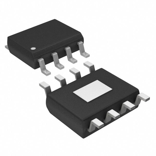
ICGOO在线商城 > 集成电路(IC) > 线性 - 放大器 - 仪表,运算放大器,缓冲器放大器 > THS3112IDDAR
- 型号: THS3112IDDAR
- 制造商: Texas Instruments
- 库位|库存: xxxx|xxxx
- 要求:
| 数量阶梯 | 香港交货 | 国内含税 |
| +xxxx | $xxxx | ¥xxxx |
查看当月历史价格
查看今年历史价格
THS3112IDDAR产品简介:
ICGOO电子元器件商城为您提供THS3112IDDAR由Texas Instruments设计生产,在icgoo商城现货销售,并且可以通过原厂、代理商等渠道进行代购。 THS3112IDDAR价格参考¥34.74-¥64.53。Texas InstrumentsTHS3112IDDAR封装/规格:线性 - 放大器 - 仪表,运算放大器,缓冲器放大器, 电流反馈 放大器 2 电路 8-SO PowerPad。您可以下载THS3112IDDAR参考资料、Datasheet数据手册功能说明书,资料中有THS3112IDDAR 详细功能的应用电路图电压和使用方法及教程。
Texas Instruments的THS3112IDDAR是一款高性能、低噪声、宽带宽的运算放大器,广泛应用于需要高精度和高速信号处理的场景。以下是该型号的主要应用场景:

 1. 通信系统
   THS3112IDDAR适用于各种通信设备,如无线基站、有线调制解调器等。其高带宽(240 MHz)和快速建立时间使其能够处理高频信号,确保数据传输的准确性和实时性。此外,其低噪声特性有助于减少信号干扰,提高通信质量。

 2. 医疗设备
   在医疗领域,THS3112IDDAR可用于心电图(ECG)、超声波成像等设备中。这些设备对信号的精确度要求极高,THS3112IDDAR的低噪声和高增益带宽积(GBW)能够确保微弱生物电信号的准确放大,帮助医生获得更清晰的诊断图像或数据。

 3. 工业自动化
   在工业自动化控制系统中,THS3112IDDAR可以用于传感器信号调理电路。例如,在温度、压力、位移等传感器的应用中,它能够将微弱的传感器输出信号放大到适合后续处理的水平,同时保持信号的完整性,避免失真。

 4. 音频处理
   对于高端音频设备,如专业音响、录音设备等,THS3112IDDAR的低失真和低噪声特性使其成为理想的选择。它可以用于前置放大器、混音器等电路中,确保音频信号在传输过程中不失真,提供高质量的声音输出。

 5. 测试与测量仪器
   在示波器、频谱分析仪等测试仪器中,THS3112IDDAR的高带宽和快速响应能力使得它能够捕捉和处理高频信号,帮助工程师进行精确的信号分析。其低噪声特性也有助于提高测量的准确性。

 6. 消费电子
   THS3112IDDAR还可以应用于一些高端消费电子产品中,如高清摄像机、VR/AR设备等。这些设备通常需要处理复杂的视频和音频信号,THS3112IDDAR的高性能可以确保信号的稳定性和清晰度。

总之,THS3112IDDAR凭借其出色的性能参数,适用于多种对信号处理要求较高的领域,特别是在需要高精度、低噪声和高速响应的应用中表现出色。
| 参数 | 数值 |
| -3db带宽 | 110MHz |
| 产品目录 | 集成电路 (IC) |
| 描述 | IC OPAMP CFA 110MHZ 8SOPWRPAD |
| 产品分类 | Linear - Amplifiers - Instrumentation, OP Amps, Buffer Amps |
| 品牌 | Texas Instruments |
| 数据手册 | http://www.ti.com/lit/pdf/slyt099 |
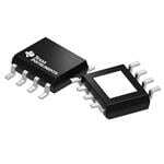
| 产品图片 |
|
| 产品型号 | THS3112IDDAR |
| rohs | 无铅 / 符合限制有害物质指令(RoHS)规范要求 |
| 产品系列 | - |
| 供应商器件封装 | 8-SO PowerPad |
| 其它名称 | 296-13334-6 |
| 包装 | Digi-Reel® |
| 压摆率 | 1550 V/µs |
| 增益带宽积 | - |
| 安装类型 | 表面贴装 |
| 封装/外壳 | 8-SOIC(0.154",3.90mm 宽)裸焊盘 |
| 工作温度 | -40°C ~ 85°C |
| 放大器类型 | 电流反馈 |
| 标准包装 | 1 |
| 电压-电源,单/双 (±) | 10 V ~ 30 V, ±5 V ~ 15 V |
| 电压-输入失调 | 3mV |
| 电流-电源 | 4.9mA |
| 电流-输入偏置 | 330nA |
| 电流-输出/通道 | 270mA |
| 电路数 | 2 |
| 设计资源 | http://www.digikey.com/product-highlights/cn/zh/texas-instruments-webench-design-center/3176 |
| 输出类型 | - |
| 配用 | /product-detail/zh/THS3112EVM/296-20544-ND/562158/product-detail/zh/THS3110EVM/296-18841-ND/863674/product-detail/zh/THS3111EVM/296-18842-ND/863675/product-detail/zh/THS3120EVM/296-18843-ND/863676/product-detail/zh/THS3121EVM/296-18844-ND/863677 |


- 商务部:美国ITC正式对集成电路等产品启动337调查
- 曝三星4nm工艺存在良率问题 高通将骁龙8 Gen1或转产台积电
- 太阳诱电将投资9.5亿元在常州建新厂生产MLCC 预计2023年完工
- 英特尔发布欧洲新工厂建设计划 深化IDM 2.0 战略
- 台积电先进制程称霸业界 有大客户加持明年业绩稳了
- 达到5530亿美元!SIA预计今年全球半导体销售额将创下新高
- 英特尔拟将自动驾驶子公司Mobileye上市 估值或超500亿美元
- 三星加码芯片和SET,合并消费电子和移动部门,撤换高东真等 CEO
- 三星电子宣布重大人事变动 还合并消费电子和移动部门
- 海关总署:前11个月进口集成电路产品价值2.52万亿元 增长14.8%

PDF Datasheet 数据手册内容提取
Texas Instruments Incorporated Amplifiers: Op Amps Expanding the usability of current-feedback amplifiers By Randy Stephens (Email: r-stephens@ti.com) Systems Specialist, Member Group Technical Staff Introduction Figure 1. VFB test circuit Although current-feedback (CFB) amplifiers have been around as long as the widely utilized voltage-feedback (VFB) amplifiers, their acceptance has been sporadic. One of the CF=220pF reasons for this is quite simple—they have a different name and therefore must be difficult and very hard to use. This is simply not true. There are numerous papers1, 2, 3 RG=187Ω RF=750Ω comparing the differences between the two amplifier types that show they are more similar to each other than +15V different. In fact, for numerous circuits, a CFB amplifier may actually yield better results due to its inherent slew- V rate advantage, lack of a gain-bandwidth product, and OUT reasonably low noise for the performance. V IN THS4012 Almost every paper written about CFB amplifiers cautions RL readers that placing a capacitor directly in the feedback path, R 100Ω Term without any resistance in series, will cause the CFB ampli- 50Ω –15V fier to oscillate. This is true, as the compensation of the amplifier is tied directly to the feedback impedance. Since a capacitor has low impedance at high frequencies, this essen- tiallyplaces a short in the feedback path that inadvertently defeats amplifier compensation, resulting in instability. Because of this limitation, there are a handful of common Figure 2. CFB test circuit with simple circuits that are not recommended for use with a CFB modification amplifier. These include integrators, some types of filters, and special feedback-compensation techniques. But what C =220pF if there was a way to make these circuits work? And what F if the solution was as simple as adding a single component? This would make it feasible to implement a CFB amplifier R =187Ω R =750Ω G F for just about every application for which a VFB amplifier could be used, with the benefits of the CFB amplifier. +15V Compensation Z This article does not explain the compensation theory of V OUT VFB and CFB amplifiers, as there are many papers written on this topic. The only thing that is important is that VIN THS3112 R there must be resistance, or impedance, in the feedback R 10L0Ω path at the open-loop intersection point to make the CFB Term 50Ω –15V amplifier stable. Figure 1 shows a traditional VFB amplifier, a THS4012, configured in a noninverting gain of +5 with a simple low- pass gain filter set at approximately 1 MHz by the straight- forward 1/(2πR C ) formula. F F If a CFB amplifier like the THS3112 is simply dropped amplifier, can now be essentially any resistance desired. into this circuit, it willoscillate and the circuit will The reader should keep in mind that this is still a high- become useless. A method of compensating the CFB speed amplifier with speeds over 100 MHz; so the feedback amplifier in this circuit is to insert a resistance, or imped- resistance should always be kept less than a few kilohms ance (Z), in the feedback path as shown in Figure 2. to minimize the effects of parasitic capacitances on the It can easily be seen that regardless of the impedance overall circuit. Conversely, minimizing the resistance too of the feedback path represented by R and C , the much will place too much of a load on the amplifier, F F impedance Z is in the amplifier’s feedback loop dictating typically degrading performance. the compensation of the amplifier. The interesting thing One of the drawbacks of adding the impedance Z in this about this configuration is that the feedback resistance manner is that the summing node at the inverting terminal (R ), which normally dictates the compensation of the is now separated from the virtual summing node. This can F 23 Analog Applications Journal 3Q 2003 www.ti.com/sc/analogapps Analog and Mixed-Signal Products
Amplifiers: Op Amps Texas Instruments Incorporated introduce errors into the system due to Figure 3. Frequency responses with resistors (gain = +5) the bias current and the dynamic signal current flowing through this impedance; but these effects are reasonably small as long as the impedance is minimized. 25 Adding impedance Z can affect input offset voltage due to the dc input bias 20 Z=200Ω current, which is typically 1 to 10 µA, 15 multiplied by the impedance Z. This resulting voltage gets multiplied by the noise gain of the circuit. Additionally, when B) 10 d a signal appears at the output, the CFB (T 5 Z=475Ω amplifier (as the name implies) relies on U O an error current flowing through the V Z=681Ω 0 invertingnode through the impedance Z, producing a signal error. However, since –5 the transimpedance of most CFB ampli- Z=1kΩ fiers is well over 100 kΩand sometimes as –10 high as several megohms, this error is also THS4012 minimized if the impedance is kept low. The –15 drift of this circuit now also relies on the 10 k 100 k 1 M 10 M 100 M 1 G temperature characteristics of impedance Frequency (Hz) Z and should not be used as a precision amplifier; but most CFB amplifiers are not used as precision amplifiers anyway due to their inherent topology limitations. Overall, these issues stated previously. This shows that there is a reasonably wide are minimal and, for most systems, can be effectively range of acceptable values for Z and does not imply that the ignored in favor of the CFB amplifier’s advantages as selection for Z is highly critical. Figure 3 also illustrates a previously stated. common trait for current-feedback amplifiers—as the feed- backimpedance is decreased, the peaking will increase. If Testing with different Z values the impedance is too low, there is a good chance that the The easiest way to see if the circuit is stable is to use a circuit will become unstable and oscillate, as illustrated by network analyzer frequency sweep. Instability can typical- the response when Z = 200 Ω. ly be seen as sharp rises in the frequency response at the Output noise amplifier’s bandwidth limitations. If the peaking is smooth, or there is no peak, then the amplifier should be stable. One element that may be very important in a system is the Figure 3 shows the frequency response of the system with output noise. Adding a resistance in the manner discussed different values of resistors for the variable Z. only makes the output noise worse. The inverting current The response of the THS4012 is also shown for reference noise of the amplifier goes through the resistance at Z and to easily compare the performance of the two systems. It creates a voltage noise. This noise then becomes multiplied is interesting that no matter what resistance is used for Z, by the circuit’s gain, which is frequency-dependent. the responses below 20 MHz look identical to each other. For a CFB amplifier, the inverting current noise is typi- This is the ultimate goal of this configuration—no differ- cally the highest noise component of the amplifier. Although ences in signal performance. For the stability part of the the CFB amplifier voltage noise is inherently very low, —— circuit, the area above 20 MHz must be examined. typically less than 3 nV/√Hz, the inverting currentnoise of —— Examining the circuits in Figures 1 and 2 shows us that most CFB amplifiers is generally around 15 to 20 pA/√Hz. the feedback impedance is dictated by the capacitor CF. The noninverting current noise is only noticeable if the Above 20 MHz, this impedance is very small—essentially source impedance is high. Using a 50-Ωenvironment creating a short from the output to the summing node. This minimizes the noninverting current noise. configuration is commonly referred to as a unity buffer with The THS3112 was designed to have very low noise. The —— the signal gain set to 1. The data sheet for the THS31124 voltage noise is 2.2 nV/√Hz, the noninverting current noise —— recommends that, in a gain of +1 under the circuit condi- is 2.9 pA/√Hz, and the critical inverting current noise is a —— tions utilized, the feedback resistance be 1 kΩ. Thus, it is low 10.8 pA/√Hz. However, multiplying the inverting current no surprise to see that when Z = 1 kΩ, the response looks noise by 1 kΩand then multiplying by the gain can alone —— very smooth and well behaved, indicating a very stable produce a very substantial output noise of about 54 nV/√Hz system. However, when Z = 681 Ω, the response also looks in the pass band. To quantify the output noise of the system, very reasonable and helps minimize the potential issues the circuits shown in Figures 1 and 2 were tested for output 24 Analog and Mixed-Signal Products www.ti.com/sc/analogapps 3Q 2003 Analog Applications Journal
Texas Instruments Incorporated Amplifiers: Op Amps noise (see Figure 4). For comparison, the THS4012, with a Keep in mind that the THS3112 has very low overall —— respectable voltage noise of 7.5 nV/√Hzand both current noise but that many other CFB amplifiers will probably —— noises of 1 pA/√Hz, is also shown in Figure 4. produce much higher noise. The only way to get around Note that the output noise of the THS4012 is the same this is if the unity-gain stability of the amplifier requires a as when using the THS3112 with Z = 475 Ω. Again, these very small resistor of, say, only 500 Ωor less. But what if responses are just like those of a VFB amplifier in the tradi- there was another way to make the CFB amplifier stable tionalconfiguration, showing that the basic functionality is andhave low noise at the same time? sound—thereare no differences between a VFB amplifier Fundamentally speaking, the circuit needs high impedance and this configuration. Figure 4 shows that although using within the feedback path only at the amplifier’s bandwidth Z = 1 kΩproduces a very stable amplifier, the output limit. At frequencies below this point, it really does not —— noise is 20 nV/√Hzhigher than that of the THS4012. matter what the impedance is, and the amplifier will work fine. The issues stated previously are also minimized, resulting in an even better system than one using pure resistors. Figure 4. Output noise (gain = +5) The first solution that comes to mind is to use an inductor. Inductors have low impedance at low frequencies and high 70 impedance at high frequencies—exactly what is desired; but their relatively large 60 Z =1kΩ size and high cost are generally considered prohibitive. An alternative component —–Hz) 50 that minimizes these disadvantages and √ Z=681Ω V/ still functions the same is the ferrite chip. n ( 40 se THS4012;alsoZ=475Ω Testing with ferrite chips oi used for Z N 30 ut Z=200Ω Ferrite chips have been available for several p ut 20 years, are relatively low-cost, and are O available in verysmall sizes—0402 and larger. Although several manufacturers 10 produce ferrite chips, testing was done with what was availablein the test lab— 0 ferrite chips from Murata’s BLM series. 10 k 100 k 1 M 10 M Examining the impedance characteristics Frequency (Hz) of these ferrites revealed several possible components that could be utilized. The first factor in determining the proper component was the ferrite’s impedance at the amplifier’s bandwidth limit. For the Figure 5. Frequency responses above 10 MHz with THS3112, this implied an impedance of ferrite chips (gain = +5) at least 600 Ωat about 150 MHz to meet stability. This can vary, as the first test results showed (see Figure 3). 35 Additionally, the Q of the ferrite chips 30 varies from grade to grade. Some have a low Q with a fairly smooth rise to the 25 Z=BLM18HD601SN1 resonance point that then subsides due to 20 inherent properties and parasitics, while other chips have a relatively high Q with a 15 B) sharp rise and fall in impedance associated (d 10 Z=BLM18HG601SN1 with them. Although either style may T U meet the impedance requirements, testing O 5 V was required to see if this Q had an effect 0 on the circuit. Again, the best way to show Z=681Ω –5 the results was to graph the frequency response of the system, as shown in –10 Figure 5. The responses below 10 MHz –15 Z=BLM18AG601SN1 were all identical to the original configu- ration. This figure concentrates on the –20 10 M 100 M 1 G stability portion of the responses above Frequency(Hz) 10 MHz. For comparison purposes, the 681-Ω, pure-resistance response is shown. 25 Analog Applications Journal 3Q 2003 www.ti.com/sc/analogapps Analog and Mixed-Signal Products
Amplifiers: Op Amps Texas Instruments Incorporated Although all of these ferrite chips have the same impedance at 100 MHz (600 Ω), Figure 6. Responses with AG series ferrite chips (gain = +5) they produced different results. The HD series high-Q chip shows a very narrow 30 and large peak that will most likely result in instability and oscillations. The AG and Z=FerriteChip 25 HG series low-Q chips both performed BLM18AGxxxSN1Series xxx=221 about the same, and either one would 20 probably produce acceptable results. The only difference is that the HG series has 15 impedance at higher frequencies and B) would probably be better suited for use (dT10 xxx=471 U with very high-speed CFB amplifiers such O 5 V as the OPA685 or the THS3202. Notice that the pure resistance has a 0 xxx=601 lower response peak than the ferrite chips. –5 Coupled with the fact that the HD series has a high Q and a high peak, this implies xxx=102 –10 that the slope of the impedance at the amplifier’s bandwidth is a factor for stabil- –15 ity. This makes a lot of sense; as it is well 10 k 100 k 1 M 10 M 100 M 1 G known that for any amplifier, if a zero Frequency(Hz) intersects the amplifier’s open-loop response at a rate of closure of 40 dB/ decade, large peaking and oscillations will most likely result.5For this circuit config- uration, if the impedance of Z has a large Figure 7. Output noise comparison (gain = +5) slope that intersects the transimpedance curve at essentially a rate of closure of 40 dB/decade, peaking and oscillations 50 also will most likely occur. By comparison, Z=681Ω a resistor intersects the transimpedance 45 curve at a rate of closure of 20 dB/decade, 40 resulting in a stable response. Even though the low-Q ferrite beads have some slope —–Hz) 35 THS4012 rcelolastuerde tios mthuecirh imlowpeedr atnhcaen, 4th0e d rBa/tdee ocfade, √V/ 30 Z=332Ω n providing improved stability. Nevertheless, ( 25 e masi nmimucizhi nags tphoiss siinbtleer ssehcotuioldn praroted uocf eclosure Nois 20 acceptable results. put 15 Z=AllFerriteChips To further expand on the usefulness of ut O 10 the ferrite chips, more testing was done utilizing the AG series in the circuit,as 5 shown in Figure 6. This figure shows that, just like the 0 10 k 100 k 1 M 10 M results for the pure resistor, the higher the impedance is, the lower the peaking. Frequency (Hz) How does this affect the output noise of the system? Figure 7 shows the output noise when the ferrite chips were used, along with the output noise of the THS4012 and some of the original resistor configurations. Inverting gain configuration As expected, due to the low frequency impedance of the All of the testing discussed so far was done with the non- ferrite chips, the noise is extremely low. This noise was the inverting gain configuration. This configuration forces the same regardless of which ferrite was used. If noise above inverting node voltage to move proportionally to the input 10 MHz was important, the impedance of these ferrite voltage applied. So how does the system work in the chips would start to increase the output noise to the same inverting gain configuration where the inverting node is extent as resistors. These tests show that there are several held at a virtual ground? The easy answer is that it works advantages of using ferrite chips over resistors. 26 Analog and Mixed-Signal Products www.ti.com/sc/analogapps 3Q 2003 Analog Applications Journal
Texas Instruments Incorporated Amplifiers: Op Amps Figure 8. Inverting gain of 5 VFB configuration Figure 9. Inverting gain of 5 CFB configuration C =220pF C =220pF F F R =750Ω R =750Ω F F +15V +15V R R G G 150Ω 150Ω Z V V IN V IN V OUT OUT R R 7Te5rmΩ THS4012 RL 7Te5rmΩ THS3112 RL 100Ω 100Ω –15V –15V exactly the same as before. Figures 8 and 9 show the test gain must be above unity gain, or 0 dB. As long as the peak circuits for this configuration. The signal gain was kept at is below 0 dB, oscillations should not occur. As in the non- a gain of 5. inverting case, using 200 Ωshows a large narrow peak that The same concepts apply for this CFB configuration as will most likely result in stability issues and/or oscillations. for the noninverting configuration. The advantage of this However, notice that above 10 MHz the same general circuit is that the attenuation is not limited to unity gain, shape occurs for both the CFB and VFB amplifiers. This is or 0 dB, like the noninverting gain circuit. Figure 10 shows caused by the amplifiers’ input and output impedances the frequency responses of this configuration with varying becoming very high above their bandwidth limit. When pure resistor values for Z. The THS4012 response is shown this occurs, there is a path for the input signal to flow for comparison purposes. through RG, through CF, and then to feed forward to the As expected, the responses all look comparable to each load. Of course, the amplifiers’ own input and output other below 10 MHz. Additionally, the resistance values capacitances also affect the amount of feed-through in the affect the stability and again show that the higher the circuit; but it is important to remember that this occurs resistance is, the better the stability. Using a resistance as above the amplifiers’ usable bandwidths. low as 475 Ωactually shows respectable performance in this Just as for the noninverting configuration, using ferrite configuration. Remember that for oscillations to occur, the chips has several advantages for the inverting configuration. Figure 10. Frequency responses with resistors (gain = –5) 15 10 5 Z=200Ω B) 0 d ( UT–5 Z=475Ω THS4012 O V–10 –15 –20 Z=1kΩ –25 10k 100k 1M 10M 100M 1G Frequency(Hz) 27 Analog Applications Journal 3Q 2003 www.ti.com/sc/analogapps Analog and Mixed-Signal Products
Amplifiers: Op Amps Texas Instruments Incorporated Figure 11 shows the frequency responses Figure 11. Frequency responses above 10 MHz of several of these chips. Figure 12 shows with ferrite chips (gain = –5) the results of using various ferrite chips from the same AG family. As expected, all of these graphs show 10 the same type of results obtained with the noninverting configuration. Using a 5 low-Q ferrite chip with high impedance Z=BLM18HD601SN1 will result in a stable system. Although the noise plots for this configuration are not 0 presented here, they will show the same type of results as the noninverting configu- B) –5 Z=BLM18HG601SN1 d ration; using ferrite chips will have the (T Z=BLM18AG601SN1 U lowest output noise of any configuration. O–10 V Conclusion –15 Although this article shows only two con- Z=681Ω figurations with capacitors in the feedback path, it shows the fundamental feasibility –20 of this compensation technique. While resistors do work very well, producing the –25 most stable responses, the drawbacks of 10 M 100 M 1 G the output noise coupled with the dc and Frequency(Hz) ac errors may limit some of the applications. Using ferrite chips helps alleviate many of these issues, producing the lowest noise of all with no dc errors or in-band ac sig- Figure 12. Frequency responses with AG series nal errors; and stability is almost as good ferrite chips (gain = –5) as when utilizing resistors. It is important to choose the proper ferrite chip with the amplifier; but this is considered normal 15 procedure for any circuit design and is no more difficult than selecting the right 10 xxx=221 amplifier for the system. This simple technique helps eliminate 5 one of the major drawbacks of using the CFB amplifier while allowing any system B) 0 d xxx=471 to enjoy many of its benefits. Designers of (T–5 xxx=601 U multiple feedback filters, for example, once O limited to the use of VFB amplifiers, can V–10 now take advantage of the superior slew –15 rates and lack of gain-bandwidth product characteristics found in the CFB amplifier. Z=FerriteChip –20 BLM18AGxxxSN1Series xxx=102 References –25 For more information related to this article, 10 k 100 k 1 M 10 M 100 M 1 G you can downloadan Acrobat Reader file Frequency(Hz) at www-s.ti.com/sc/techlit/litnumberand replace “litnumber”with the TI Lit. # for the materials listed below. Document Title TI Lit. # Related Web sites 1. “Voltage Feedback Vs. Current Feedback analog.ti.com Op Amps,” Application Report . . . . . . . . . . . . . .slva051 www.ti.com/sc/device/partnumber 2. “The Current-Feedback Op Amp: A High- Replace partnumberwith OPA685, THS3112, THS3202or Speed Building Block,” Application Bulletin . . .sboa076 THS4012 3. “Current Feedback Amplifiers: Review, Stability Analysis, and Applications,” Application Bulletin . . . . . . . . . . . . . . . . . . . . . . .sboa081 4. “Low-Noise, High-Speed Current Feedback Amplifiers,” Data Sheet . . . . . . . . . . . . . . . . . . . .slos385 5. “Effect of Parasitic Capacitance in Op Amp Circuits,” Application Report . . . . . . . . . . . . . . .sloa013 28 Analog and Mixed-Signal Products www.ti.com/sc/analogapps 3Q 2003 Analog Applications Journal
IMPORTANT NOTICE TIWorldwide Technical Support Texas Instruments Incorporated and its subsidiaries (TI) reserve Internet the right to make corrections, modifications, enhancements, improvements, and other changes to its products and services at TI Semiconductor Product Information Center Home Page any time and to discontinue any product or service without notice. support.ti.com Customers should obtain the latest relevant information before TI Semiconductor KnowledgeBase Home Page placing orders and should verify that such information is current support.ti.com/sc/knowledgebase and complete. All products are sold subject to TI's terms and Product Information Centers conditions of sale supplied at the time of order acknowledgment. Americas TI warrants performance of its hardware products to the Phone +1(972) 644-5580 Fax +1(972) 927-6377 specifications applicable at the time of sale in accordance with TI's Internet/Email support.ti.com/sc/pic/americas.htm standard warranty. Testing and other quality control techniques are Europe, Middle East, and Africa used to the extent TI deems necessary to support this warranty. Phone Except where mandated by government requirements, testing of Belgium (English) +32 (0) 27 45 54 32 Netherlands (English) +31 (0) 546 87 95 45 all parameters of each product is not necessarily performed. Finland (English) +358 (0) 9 25173948 Russia +7 (0) 95 7850415 France +33 (0) 1 30 70 11 64 Spain +34 902 35 40 28 TI assumes no liability for applications assistance or customer Germany +49 (0) 8161 80 33 11 Sweden (English) +46 (0) 8587 555 22 product design. Customers are responsible for their products and Israel (English) 1800 949 0107 United Kingdom +44 (0) 1604 66 33 99 applications using TI components. To minimize the risks Italy 800 79 11 37 associated with customer products and applications, customers Fax +(49) (0) 8161 80 2045 should provide adequate design and operating safeguards. Internet support.ti.com/sc/pic/euro.htm Japan TI does not warrant or represent that any license, either express or Fax implied, is granted under any TI patent right, copyright, mask work International +81-3-3344-5317 Domestic 0120-81-0036 right, or other TI intellectual property right relating to any Internet/Email combination, machine, or process in which TI products or services International support.ti.com/sc/pic/japan.htm are used. Information published by TI regarding third-party Domestic www.tij.co.jp/pic products or services does not constitute a license from TI to use Asia such products or services or a warranty or endorsement thereof. Phone Use of such information may require a license from a third party International +886-2-23786800 under the patents or other intellectual property of the third party, or a Domestic Toll-Free Number Toll-Free Number license from TI under the patents or other intellectual property of TI. Australia 1-800-999-084 New Zealand 0800-446-934 China 800-820-8682 Philippines 1-800-765-7404 Reproduction of information in TI data books or data sheets is Hong Kong 800-96-5941 Singapore 800-886-1028 permissible only if reproduction is without alteration and is Indonesia 001-803-8861-1006 Taiwan 0800-006800 accompanied by all associated warranties, conditions, limitations, Korea 080-551-2804 Thailand 001-800-886-0010 Malaysia 1-800-80-3973 and notices. Reproduction of this information with alteration is an Fax 886-2-2378-6808 Email tiasia@ti.com unfair and deceptive business practice. TI is not responsible or Internet support.ti.com/sc/pic/asia.htm ti-china@ti.com liable for such altered documentation. C011905 Resale of TI products or services with statements different from or Safe Harbor Statement: This publication may contain forward- beyond the parameters stated by TI for that product or service looking statements that involve a number of risks and voids all express and any implied warranties for the associated TI uncertainties. These “forward-looking statements” are intended product or service and is an unfair and deceptive business to qualify for the safe harbor from liability established by the practice. TI is not responsible or liable for any such statements. Private Securities Litigation Reform Act of 1995. These forward- Following are URLs where you can obtain information on other looking statements generally can be identified by phrases such Texas Instruments products and application solutions: as TI or its management “believes,” “expects,” “anticipates,” “foresees,” “forecasts,” “estimates” or other words or phrases Products of similar import. Similarly, such statements herein that describe Amplifiers amplifier.ti.com the company's products, business strategy, outlook, objectives, Data Converters dataconverter.ti.com plans, intentions or goals also are forward-looking statements. All such forward-looking statements are subject to certain risks DSP dsp.ti.com and uncertainties that could cause actual results to differ Interface interface.ti.com materially from those in forward-looking statements. Please Logic logic.ti.com refer to TI's most recent Form 10-K for more information on the Power Mgmt power.ti.com risks and uncertainties that could materially affect future results Microcontrollers microcontroller.ti.com of operations. We disclaim any intention or obligation to update any forward-looking statements as a result of developments Applications occurring after the date of this publication. Audio www.ti.com/audio Trademarks: All trademarks are the property of their Automotive www.ti.com/automotive respective owners. Broadband www.ti.com/broadband Digital control www.ti.com/digitalcontrol Mailing Address: Texas Instruments Military www.ti.com/military Post Office Box 655303 Optical Networking www.ti.com/opticalnetwork Dallas, Texas 75265 Security www.ti.com/security Telephony www.ti.com/telephony © 2005 Texas Instruments Incorporated Video & Imaging www.ti.com/video Wireless www.ti.com/wireless SLYT099
 Datasheet下载