ICGOO在线商城 > 集成电路(IC) > 时钟/计时 - 时钟缓冲器,驱动器 > SY10EP11UKG
 Datasheet下载
- 型号: SY10EP11UKG
- 制造商: Micrel
- 库位|库存: xxxx|xxxx
- 要求:
| 数量阶梯 | 香港交货 | 国内含税 |
| +xxxx | $xxxx | ¥xxxx |
查看当月历史价格
查看今年历史价格
SY10EP11UKG产品简介:
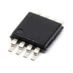
ICGOO电子元器件商城为您提供SY10EP11UKG由Micrel设计生产,在icgoo商城现货销售,并且可以通过原厂、代理商等渠道进行代购。 SY10EP11UKG价格参考。MicrelSY10EP11UKG封装/规格:时钟/计时 - 时钟缓冲器,驱动器, Clock Fanout Buffer (Distribution) IC 1:2 3GHz 8-TSSOP, 8-MSOP (0.118", 3.00mm Width)。您可以下载SY10EP11UKG参考资料、Datasheet数据手册功能说明书,资料中有SY10EP11UKG 详细功能的应用电路图电压和使用方法及教程。
Microchip Technology的SY10EP11UKG是一款属于时钟缓冲器和驱动器类别的高速时钟分配器件,主要应用于需要高精度、低抖动时钟信号分配的场合。

该芯片常用于通信设备、网络设备、测试仪器、工业控制系统以及高性能计算系统中,作为时钟信号的缓冲与驱动,确保多个器件共享一个稳定、低偏移的时钟源。其差分输入/输出设计,支持PECL电平,适用于高速数据传输和同步系统。

此外,SY10EP11UKG也可用于服务器、交换机、路由器等设备中的时钟树架构,提升系统稳定性与同步性能,适用于需要高频时钟信号处理的场景。
| 参数 | 数值 |
| 产品目录 | 集成电路 (IC)半导体 |
| 描述 | IC CLK BUFFER 1:2 3GHZ 8MSOP缓冲器和线路驱动器 2.5-5V 1:2 PECL Fanout Buffer (I Temp, Green) |
| 产品分类 | |
| 品牌 | Micrel |
| 产品手册 | |
| 产品图片 |
|
| rohs | 符合RoHS无铅 / 符合限制有害物质指令(RoHS)规范要求 |
| 产品系列 | 逻辑集成电路,缓冲器和线路驱动器,Micrel SY10EP11UKG100EP, ECL Pro® |
| 数据手册 | |
| 产品型号 | SY10EP11UKG |
| PCN组件/产地 | |
| 产品目录页面 | |
| 产品种类 | 缓冲器和线路驱动器 |
| 传播延迟时间 | 220 ps, 240 ps |
| 供应商器件封装 | 8-MSOP |
| 其它名称 | 576-2038-5 |
| 包装 | 管件 |
| 商标 | Micrel |
| 安装类型 | 表面贴装 |
| 安装风格 | SMD/SMT |
| 封装 | Tube |
| 封装/外壳 | 8-TSSOP,8-MSOP(0.118",3.00mm 宽) |
| 封装/箱体 | MSOP-8 |
| 工作温度 | -40°C ~ 85°C |
| 工厂包装数量 | 100 |
| 差分-输入:输出 | 是/是 |
| 最大工作温度 | + 85 C |
| 最小工作温度 | - 40 C |
| 极性 | Non-Inverting |
| 标准包装 | 100 |
| 比率-输入:输出 | 1:2 |
| 电压-电源 | 2.375 V ~ 5.5 V |
| 电源电压-最大 | +/- 5.5 V |
| 电源电压-最小 | +/- 2.37 V |
| 电源电流 | 25 mA |
| 电路数 | 1 |
| 类型 | 扇出缓冲器(分配) |
| 系列 | SY100EP11U |
| 输入 | LVECL,LVPECL |
| 输入线路数量 | 1 |
| 输出 | LVECL,LVPECL |
| 输出类型 | ECL, LVPECL, PECL |
| 输出线路数量 | 2 |
| 频率-最大值 | 3GHz |


- 商务部:美国ITC正式对集成电路等产品启动337调查
- 曝三星4nm工艺存在良率问题 高通将骁龙8 Gen1或转产台积电
- 太阳诱电将投资9.5亿元在常州建新厂生产MLCC 预计2023年完工
- 英特尔发布欧洲新工厂建设计划 深化IDM 2.0 战略
- 台积电先进制程称霸业界 有大客户加持明年业绩稳了
- 达到5530亿美元!SIA预计今年全球半导体销售额将创下新高
- 英特尔拟将自动驾驶子公司Mobileye上市 估值或超500亿美元
- 三星加码芯片和SET,合并消费电子和移动部门,撤换高东真等 CEO
- 三星电子宣布重大人事变动 还合并消费电子和移动部门
- 海关总署:前11个月进口集成电路产品价值2.52万亿元 增长14.8%


PDF Datasheet 数据手册内容提取
ECL Pro™ 2.5V/3.3V/5V 1:2 DIFFERENTIAL SY10EP11U ECL Pro™ Micrel, Inc. SY100EP11U PECL/LVPECL/ECL SY10EP11U SY100EP11U FANOUT BUFFER FEATURES ■ 2.5V, 3.3V and 5V power supply options ■ Guaranteed AC parameters over temperature: ECL Pro™ • f > 3.0GHz MAX • <20ps output-to-output skew DESCRIPTION • <200ps t /t r f • <300ps propagation delay The SY10/100EP11U is a precision, high-speed 1:2 ■ Wide temperature range: –40°C to +85°C differential fanout buffer. Having within-device skews and ■ Available in 8-pin (3mm) MSOP and SOIC packages output transition times significantly improved over the EL11V, the EP11U is ideally suited for those applications which require the ultimate in AC performance. The differential inputs of the EP11U employ clamping circuitry to maintain stability under open input conditions. If the inputs are left open, the Q outputs will go LOW. CROSS REFERENCE TABLE PIN NAMES Micrel Semiconductor ON Semiconductor Pin Function SY10EP11UZI/KI MC10EP11D/DT D PECL, LVPECL, ECL, LVECL Clock or Data Input: Internal 75kΩ pulldown resistor. If left floating, SY10EP11UZI/KI MC10LVEP11D/DT pin defaults LOW, Q goes LOW. OUT SY100EP11UZI/KI MC100EP11D/DT /D PECL, LVPECL, ECL, LVECL complementary SY100EP11UZI/KI MC100LVEP11D/DT Clock or Data Input: Internal 75kΩ pull-up and down resistors. If left open, default is V /2. When CC the input is not used, it can be left open. Q0, /Q0 PECL, LVPECL, ECL, LVECL Outputs: Q1, /Q1 Terminates to V –2V. CC V Positive Power Supply: Bypass with 0.1µF//0.01µF CC low ESR capacitors. V Negative Power Supply: For PECL operation, EE connect to GND. ECL Pro is a trademark of Micrel, Inc. M9999-111606 Rev.: D Amendment: /0 1 hbwhelp@micrel.com or (408) 955-1690 Issue Date: November 2005
ECL Pro™ SY10EP11U Micrel, Inc. SY100EP11U PACKAGE/ORDERING INFORMATION Ordering Information(1) Package Operating Package Lead Q0 1 8 VCC Part Number Type Range Marking Finish V CC SY10EP11UKC K8-1 Commercial HP11 Sn-Pb /Q0 2 75kΩ 7 D SY10EP11UKCTR(2) K8-1 Commercial HP11 Sn-Pb V EE SY100EP11UKC K8-1 Commercial XP11 Sn-Pb Q1 3 6 /D 75kΩ 75kΩV SY100EP11UKCTR(2) K8-1 Commercial XP11 Sn-Pb CC /Q1 4 VEE 5 VEE SY10EP11UZC Z8-1 Commercial HEP11U Sn-Pb V EE SY10EP11UZCTR(2) Z8-1 Commercial HEP11U Sn-Pb 8-pin MSOP and SOIC Packages SY100EP11UZC Z8-1 Commercial XEP11U Sn-Pb SY100EP11UZCTR(2) Z8-1 Commercial XEP11U Sn-Pb SY10EP11UKI K8-1 Industrial HP11 Sn-Pb SY10EP11UKITR(2) K8-1 Industrial HP11 Sn-Pb SY100EP11UKI K8-1 Industrial XP11 Sn-Pb SY100EP11UKITR(2) K8-1 Industrial XP11 Sn-Pb SY10EP11UZI Z8-1 Industrial HEP11U Sn-Pb SY10EP11UZITR(2) Z8-1 Industrial HEP11U Sn-Pb SY100EP11UZI Z8-1 Industrial XEP11U Sn-Pb SY100EP11UZITR(2) Z8-1 Industrial XEP11U Sn-Pb SY10EP11UKG(3) K8-1 Industrial HP11 with Pb-Free Pb-Free bar-line indicator NiPdAu SY10EP11UKGTR(2, 3) K8-1 Industrial HP11 with Pb-Free Pb-Free bar-line indicator NiPdAu SY100EP11UKG(3) K8-1 Industrial XP11 with Pb-Free Pb-Free bar-line indicator NiPdAu SY100EP11UKGTR(2, 3) K8-1 Industrial XP11 with Pb-Free Pb-Free bar-line indicator NiPdAu SY10EP11UZG(3) Z8-1 Industrial HEP11U with Pb-Free Pb-Free bar-line indicator NiPdAu SY10EP11UZGTR(2, 3) Z8-1 Industrial HEP11U with Pb-Free Pb-Free bar-line indicator NiPdAu SY100EP11UZG(3) Z8-1 Industrial XEP11U with Pb-Free Pb-Free bar-line indicator NiPdAu SY100EP11UZGTR(2, 3) Z8-1 Industrial XEP11U with Pb-Free Pb-Free bar-line indicator NiPdAu Notes: 1. Contact factory for die availability. Dice are guaranteed at T = 25°C, DC Electricals only. A 2. Tape and Reel. 3. Pb-Free package is recommended for new designs. M9999-111605 2 hbwhelp@micrel.com or (408) 955-1690
ECL Pro™ SY10EP11U Micrel, Inc. SY100EP11U ABSOLUTE MAXIMUM RATINGS(1) Symbol Rating Value Unit V —V Power Supply Voltage 6V V CC EE V Input Voltage (V = 0V, V not more negative than V ) –6.0 to 0 V IN CC IN EE Input Voltage (V = 0V, V not more positive than V ) +6.0 to 0 V EE IN CC I Output Current –Continuous 50 mA OUT –Surge 100 T Operating Temperature Range –40 to +85 °C A T Lead Temperature (soldering, 20sec.) 260 °C LEAD T Storage Temperature Range –65 to +150 °C store θ Package Thermal Resistance –Still-Air (SOIC) 160 °C/W JA (Junction-to-Ambient) –500lfpm (SOIC) 109 –Still-Air (MSOP) 206 °C/W –500lfpm (MSOP) 155 θ Package Thermal Resistance (SOIC) 39 °C/W JC (Junction-to-Case) (MSOP) 39 Note: 1. Permanent device damage may occur if absolute maximum ratings are exceeded. This is a stress rating only and functional operation is not implied at conditions other than those detailed in the operational sections of this data sheet. Exposure to absolute maximum ratlng conditions for extended periods may affect device reliability. DC ELECTRICAL CHARACTERISTICS(1) T = –40°C T = +25°C T = +85°C A A A Symbol Parameter Min. Typ. Max. Min. Typ. Max. Min. Typ. Max. Unit Condition V Power Supply Voltage V CC (PECL) 4.5 5.0 5.5 4.5 5.0 5.5 4.5 5.0 5.5 (LVPECL) 2.37 — 3.8 2.37 — 3.8 2.37 — 3.8 (ECL) –5.5 –5.0 –4.5 –5.5 –5.0 –4.5 –5.5 –5.0 –4.5 (LVECL) –3.8 –3.3 –2.37 –3.8 –3.3 –2.37 –3.8 –3.3 –2.37 I Power Supply Current EE SY10EP11U — — 37 — 25 39 — — 40 mA SY100EP11U — — 44 — 30 44 — — 44 mA I Input HIGH Current — — 150 — — 150 — — 150 µA V = V IH IN IH I Input LOW Current D 0.5 — — 0.5 — — 0.5 — — µA V = V IL IN IL /D –150 — — –150 — — –150 — — µA V = V IN IL C Input Capacitance (MSOP) — — — — 1.0 — — — — pF IN (SOIC) — — — — 1.35 — — — — pF Note: 1. 10/100KEP circuits are designed to meet the DC specifications shown in the above table after thermal equilibrium has been established. The circuit is in a test socket or mounted on a printed circuit board and traverse airflow greater than 500lfpm is maintained. M9999-111606 3 hbwhelp@micrel.com or (408) 955-1690
ECL Pro™ SY10EP11U Micrel, Inc. SY100EP11U (10KEP) LVPECL DC ELECTRICAL CHARACTERISTICS(1) V = 2.5V ±5%, V = 0V. CC EE T = –40°C T = +25°C T = +85°C A A A Symbol Parameter Min. Typ. Max. Min. Typ. Max. Min. Typ. Max. Unit Condition VOL Output LOW Voltage 565 690 815 630 755 880 690 815 940 mV 50Ω to VCC–2V VOH Output HIGH Voltage 1365 1490 1615 1430 1555 1680 1490 1615 1740 mV 50Ω to VCC–2V V Input HIGH Voltage(2) 1.2 — V 1.2 — V 1.2 — V V IHCMR CC CC CC Common Mode Range (10KEP) LVPECL DC ELECTRICAL CHARACTERISTICS(1) V = 3.3V ±10%, V = 0V. CC EE T = –40°C T = +25°C T = +85°C A A A Symbol Parameter Min. Typ. Max. Min. Typ. Max. Min. Typ. Max. Unit Condition V Input LOW Voltage 1365 — 1690 1430 — 1755 1490 — 1815 mV IL (Single-Ended) V Input HIGH Voltage 2090 — 2415 2155 — 2480 2215 — 2540 mV IH (Single-Ended) VOL Output LOW Voltage 1365 1490 1615 1430 1555 1680 1490 1615 1740 mV 50Ω to VCC–2V VOH Output HIGH Voltage 2165 2290 2415 2230 2355 2480 2290 2415 2540 mV 50Ω to VCC–2V V Input HIGH Voltage(2) 1.2 — V 1.2 — V 1.2 — V V IHCMR CC CC CC Common Mode Range (10KEP) PECL DC ELECTRICAL CHARACTERISTICS(1) V = 5.0V ±10%, V = 0V. CC EE T = –40°C T = +25°C T = +85°C A A A Symbol Parameter Min. Typ. Max. Min. Typ. Max. Min. Typ. Max. Unit Condition V Input LOW Voltage 3065 — 3390 3130 — 3455 3190 — 3515 mV IL (Single-Ended) V Input HIGH Voltage 3790 — 4115 3855 — 4180 3915 — 4240 mV IH (Single-Ended) VOL Outuput LOW Voltage 3065 3190 3315 3130 3255 3380 3190 3315 3440 mV 50Ω to VCC–2V VOH Output HIGH Voltage 3865 3990 4115 3930 4055 4180 3990 4115 4240 mV 50Ω to VCC–2V V Input HIGH Voltage(2) IHCMR 1.2 — V 1.2 — V 1.2 — V V Common Mode Range CC CC CC No tes: 1. 10KEP circuits are designed to meet the DC specifications shown in the above table after thermal equilibrium has been established. The circuit is in a test socket or mounted on a printed circuit board and traverse airflow greater than 500lfpm is maintained. Input and output parameters are at V = CC 2.5V. They vary 1:1 with V . CC 2. The V range is referenced to the most positive side of the differential input signal. See “Input Waveform” section. Single-ended input CLK pin IHCMR operation is limited to VCC ≥3.0V in PECL mode. M9999-111605 4 hbwhelp@micrel.com or (408) 955-1690
ECL Pro™ SY10EP11U Micrel, Inc. SY100EP11U (10KEP) ECL/LVECL DC ELECTRICAL CHARACTERISTICS(3) V = 0V, V = –5.5V to –2.375V. CC EE T = –40°C T = +25°C T = +85°C A A A Symbol Parameter Min. Typ. Max. Min. Typ. Max. Min. Typ. Max. Unit Condition V Input LOW Voltage –1935 — –1610 –1870 — –1545 –1810 — –1485 mV IL (Single-Ended) V Input HIGH Voltage –1210 — –885 –1145 — –820 –1085 — –760 mV IH (Single-Ended) VOL Outuput LOW Voltage –1935 –1810 –1685 –1870 –1745 –1620 –1810 –1685 –1560 mV 50Ω to VCC–2V VOH Output HIGH Voltage –1135 –1010 –885 –1070 –945 –820 –1010 –885 –760 mV 50Ω to VCC–2V V Input HIGH Voltage(4) IHCMR V +1.2 0.0 V +1.2 0.0 V +1.2 0.0 V Common Mode Range EE EE EE (100KEP) LVPECL DC ELECTRICAL CHARACTERISTICS(3) V = 2.5V ±5%. CC T = –40°C T = +25°C T = +85°C A A A Symbol Parameter Min. Typ. Max. Min. Typ. Max. Min. Typ. Max. Unit Condition VOL Outuput LOW Voltage 555 680 805 555 680 805 555 680 805 mV 50Ω to VCC–2V VOH Output HIGH Voltage 1355 1480 1605 1355 1480 1605 1355 1480 1605 mV 50Ω to VCC–2V V Input HIGH Voltage(4) 1.2 — V 1.2 — V 1.2 — V V IHCMR CC CC CC Common Mode Range (100KEP) LVPECL DC ELECTRICAL CHARACTERISTICS(3) V = 3.3V ±10%, V = 0V. CC EE T = –40°C T = +25°C T = +85°C A A A Symbol Parameter Min. Typ. Max. Min. Typ. Max. Min. Typ. Max. Unit Condition V Input LOW Voltage 1355 — 1675 1355 — 1675 1355 — 1675 mV IL (Single-Ended) V Input HIGH Voltage 2075 — 2420 2075 — 2420 2075 — 2420 mV IH (Single-Ended) VOL Output LOW Voltage 1355 1480 1605 1355 1480 1605 1355 1480 1605 mV 50Ω to VCC–2V VOH Output HIGH Voltage 2155 2280 2405 2155 2280 2405 2155 2280 2405 mV 50Ω to VCC–2V V Input HIGH Voltage(4) 1.2 — V 1.2 — V 1.2 — V V IHCMR CC CC CC Common Mode Range Notes: 3. 10KEP circuits are designed to meet the DC specifications shown in the above table after thermal equilibrium has been established. The circuit is in a test socket or mounted on a printed circuit board and traverse airflow greater than 500lfpm is maintained. 4. The V range is referenced to the most positive side of the differential input signal. See “Input Waveform” section. Single-ended input CLK pin IHCMR operation is limited to V ≤–3.0V in ECL/LVECL mode. EE M9999-111606 5 hbwhelp@micrel.com or (408) 955-1690
ECL Pro™ SY10EP11U Micrel, Inc. SY100EP11U (100KEP) PECL DC ELECTRICAL CHARACTERISTICS(5) V = 5.0V ±10%, V = 0V. CC EE T = –40°C T = +25°C T = +85°C A A A Symbol Parameter Min. Typ. Max. Min. Typ. Max. Min. Typ. Max. Unit Condition V Input LOW Voltage 3055 — 3375 3055 — 3375 3055 — 3375 mV IL (Single-Ended) V Input HIGH Voltage 3775 — 4120 3775 — 4120 3775 — 4120 mV IH (Single-Ended) VOL Outuput LOW Voltage 3055 3180 3305 3055 3180 3305 3055 3180 3305 mV 50Ω to VCC–2V VOH Output HIGH Voltage 3855 3980 4105 3855 3980 4105 3855 3980 4105 mV 50Ω to VCC–2V V Input HIGH Voltage(6) IHCMR 2.0 — V 2.0 — V 2.0 — V V Common Mode Range CC CC CC Notes: 5. 100KEP circuits are designed to meet the DC specifications shown in the above table after thermal equilibrium has been established. The circuit is in a test socket or mounted on a printed circuit board and traverse airflow greater than 500lfpm is maintained. Input and output parameters are at V = CC 5.0V. They vary 1:1 with V . CC 6. The V range is referenced to the most positive side of the differential input signal. See “Input Waveform” section. Single-ended input CLK pin IHCMR operation is limited to V ≥3.0V in PECL mode. CC (100KEP) ECL/LVECL DC ELECTRICAL CHARACTERISTICS(7) V = 0V, V = –5.5V to –2.375V. CC EE T = –40°C T = +25°C T = +85°C A A A Symbol Parameter Min. Typ. Max. Min. Typ. Max. Min. Typ. Max. Unit Condition V Input LOW Voltage –1945 — –1625 –1945 — –1625 –1945 — –1625 mV IL (Single-Ended) V Input HIGH Voltage –1225 — –880 –1225 — –880 –1225 — –880 mV IH (Single-Ended) VOL Outuput LOW Voltage –1945 –1820 –1695 –1945 –1820 –1695 –1945 –1820 –1695 mV 50Ω to VCC–2V VOH Output HIGH Voltage –1145 –1020 –895 –1145 –1020 –895 –1145 –1020 –895 mV 50Ω to VCC–2V V Input HIGH Voltage(8) IHCMR V +1.2 0.0 V +1.2 0.0 V +1.2 0.0 V Common Mode Range EE EE EE Notes: 7. 100KEP circuits are designed to meet the DC specifications shown in the above table after thermal equilibrium has been established. The circuit is in a test socket or mounted on a printed circuit board and traverse airflow greater than 500lfpm is maintained. 8. The V range is referenced to the most positive side of the differential input signal. See “Input Waveform” section. Single-ended input CLK pin IHCMR operation is limited to V ≤–3.0V in ECL/LVECL mode. EE M9999-111605 6 hbwhelp@micrel.com or (408) 955-1690
ECL Pro™ SY10EP11U Micrel, Inc. SY100EP11U AC ELECTRICAL CHARACTERISTICS V = 0V; V = –5.5V to –2.375V or V = 2.375V to 5.5V, V = 0V. CC EE CC EE T = –40°C T = +25°C T = +85°C A A A Symbol Parameter Min. Typ. Max. Min. Typ. Max. Min. Typ. Max. Unit Condition f Max. Toggle Frequency(9) 3 — — 3 — — 3 — — GHz MAX t Propagation Delay (Differential) PLH t D to Q, /Q 140 200 250 160 220 270 180 240 300 ps V = 3.3/5V PHL CC D to Q, /Q 170 230 300 180 240 310 210 270 360 ps V = 2.5V CC t Within-Device Skew(10)Q, /Q — 5 20 — 5 20 — 5 20 ps SKEW Part-to-Part Skew(10) — — 130 — — 130 — — 150 ps V = 3.3/5V CC — — 110 — — 110 — — 120 ps V = 2.5V CC t Cycle-to-Cycle Jitter (RMS) — 0.2 <1 — 0.2 <1 — 0.2 <1 ps JITTER RMS V Input Swing(11) 150 800 1200 150 800 1200 150 800 1200 mV DIFF t t Output Rise/Fall Time 70 110 170 80 120 180 100 140 200 ps r, f (20% to 80%) Notes: 9. Measured with 750mV input signal, 50% duty cycle. All loading with a 50Ω to V –2.0V. CC 10.Skew is measured between outputs under identical transitions. Duty cycle skew is defined only for differential operation when the delays are measured from the cross point of the inputs to the cross point of the outputs. 11.See “Input Waveform.” INPUT WAVEFORM D V IHCMR V =150mV to 1200mV DIFF /D M9999-111606 7 hbwhelp@micrel.com or (408) 955-1690
ECL Pro™ SY10EP11U Micrel, Inc. SY100EP11U TERMINATION RECOMMENDATIONS +3.3V R1(cid:0) R1(cid:0) +3.3V 130Ω 130Ω +3.3V Z = 50Ω O Z = 50Ω O R2(cid:0) R2(cid:0) 82Ω 82Ω V = V –2V t CC Figure 1. Parallel Termination–Thevenin Equivalent Notes: 1. For +2.5V systems: R1 = 250Ω, R2 = 62.5Ω. 2. For +5.0V systems: R1 = 82Ω. +5.0V or(cid:0) +5.0V or(cid:0) +3.3V Z= 50Ω(cid:0) +3.3V Z= 50Ω(cid:0) R2 = 130Ω 50Ω(cid:0) 50Ω(cid:0) “source”(cid:0) “destination”(cid:0) 50Ω(cid:0) R (cid:0) b Figure 2. Three-Resistor “Y–Termination” Notes: 1. Power-saving alternative to Thevenin termination. 2. Place termination resistors as close to destination inputs as possible. 3. R resistor sets the DC bias voltage equal to V. For +3.3V systems R = 46Ω to 50Ω. For +5V systems, R = 110Ω. b t b b M9999-111605 8 hbwhelp@micrel.com or (408) 955-1690
ECL Pro™ SY10EP11U Micrel, Inc. SY100EP11U 8-PIN MSOP (K8-1) Rev. 01 M9999-111606 9 hbwhelp@micrel.com or (408) 955-1690
ECL Pro™ SY10EP11U Micrel, Inc. SY100EP11U 8-PIN SOIC (Z8-1) Rev. 03 MICREL, INC. 2180 FORTUNE DRIVE SAN JOSE, CA 95131 USA TEL + 1 (408) 944-0800 FAX + 1 (408) 474-1000 WEB http://www.micrel.com The information furnished by Micrel in this datasheet is believed to be accurate and reliable. However, no responsibility is assumed by Micrel for its use. Micrel reserves the right to change circuitry and specifications at any time without notification to the customer. Micrel Products are not designed or authorized for use as components in life support appliances, devices or systems where malfunction of a product can reasonably be expected to result in personal injury. Life support devices or systems are devices or systems that (a) are intended for surgical implant into the body or (b) support or sustain life, and whose failure to perform can be reasonably expected to result in a significant injury to the user. A Purchaser’s use or sale of Micrel Products for use in life support appliances, devices or systems is at Purchaser’s own risk and Purchaser agrees to fully indemnify Micrel for any damages resulting from such use or sale. © 2005 Micrel, Incorporated. M9999-111605 10 hbwhelp@micrel.com or (408) 955-1690
Mouser Electronics Authorized Distributor Click to View Pricing, Inventory, Delivery & Lifecycle Information: M icrel: SY100EP11UKG TR M icrochip: SY10EP11UZG SY10EP11UKG SY100EP11UZG SY100EP11UKG SY10EP11UZG-TR SY10EP11UKG-TR SY100EP11UZG-TR SY100EP11UKG-TR