
 Datasheet下载
- 型号: ST205C107MAJ10
- 制造商: AVX
- 库位|库存: xxxx|xxxx
- 要求:
| 数量阶梯 | 香港交货 | 国内含税 |
| +xxxx | $xxxx | ¥xxxx |
查看当月历史价格
查看今年历史价格
ST205C107MAJ10产品简介:
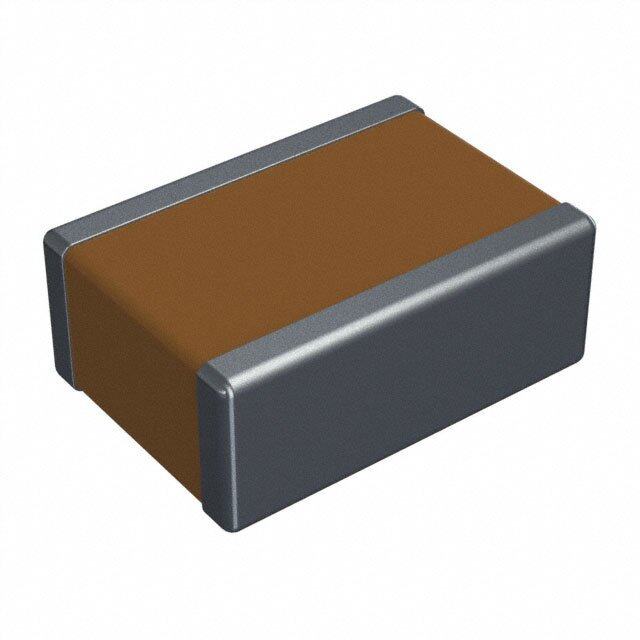
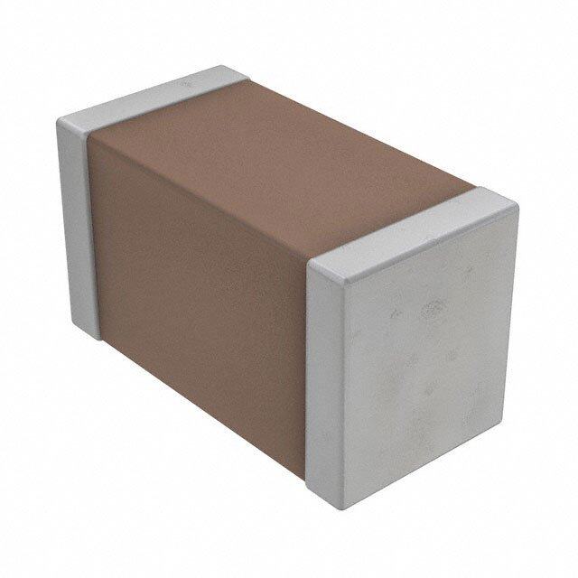
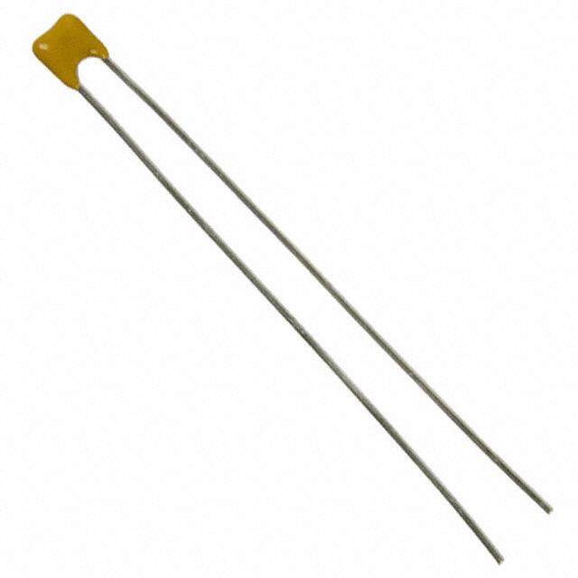
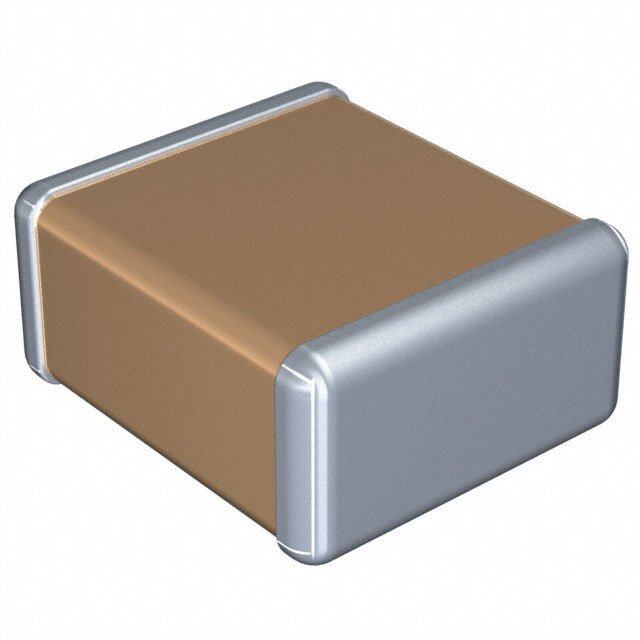
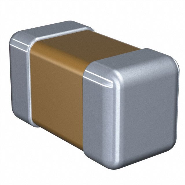
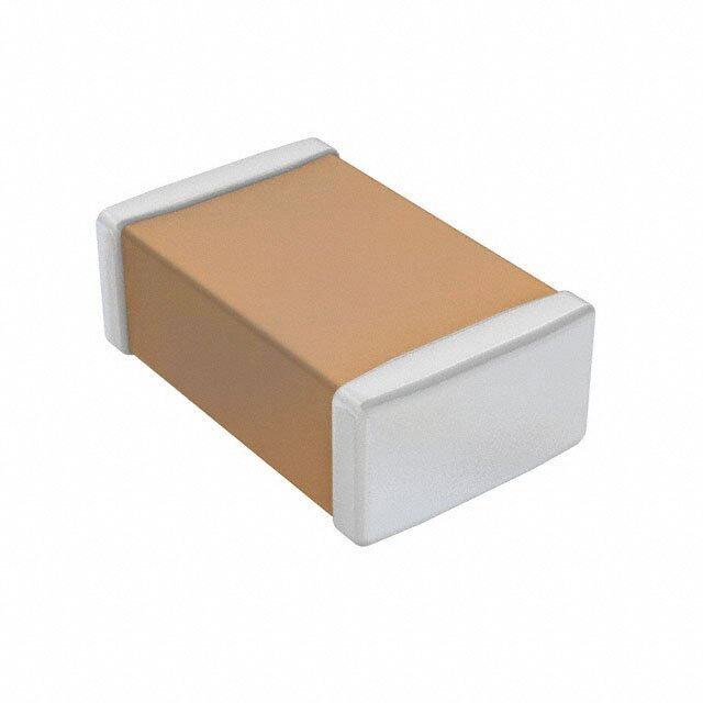
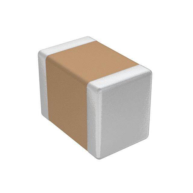
ICGOO电子元器件商城为您提供ST205C107MAJ10由AVX设计生产,在icgoo商城现货销售,并且可以通过原厂、代理商等渠道进行代购。 ST205C107MAJ10价格参考。AVXST205C107MAJ10封装/规格:陶瓷电容器, 100µF ±20% 50V 陶瓷电容器 X7R 堆栈式 SMD,20 个 J 型接脚。您可以下载ST205C107MAJ10参考资料、Datasheet数据手册功能说明书,资料中有ST205C107MAJ10 详细功能的应用电路图电压和使用方法及教程。
AVX Corporation的ST205C107MAJ10是一款陶瓷电容器,属于多层陶瓷电容器(MLCC)的一种。该型号电容器具有较高的电容值和良好的稳定性,适用于多种电子设备和系统中。

其主要应用场景包括:

1. 电源管理电路:用于滤波、去耦和储能,提升电源稳定性,常见于DC-DC转换器、电源模块等。

2. 工业控制系统:如PLC(可编程逻辑控制器)、工业计算机和自动化设备中,用于信号处理和电源滤波。

3. 通信设备:包括基站、路由器和交换机等通信基础设施,用于高频信号滤波和稳定电路性能。

4. 汽车电子系统:如车载信息娱乐系统、发动机控制单元(ECU)和电池管理系统(BMS),适用于对可靠性要求较高的场景。

5. 消费类电子产品:如智能手机、平板电脑和笔记本电脑,用于电源去耦和信号处理。

该电容器具有较高的可靠性,适用于需要稳定性能和高电容密度的电路设计,尤其适合空间受限但性能要求较高的应用场合。
| 参数 | 数值 |
| 产品目录 | |
| 描述 | CAP CER 100UF 50V 20% X7R SMD多层陶瓷电容器MLCC - 含引线 50volts 100uF 20% X7R NCNR |
| 产品分类 | |
| 品牌 | AVX Corporation |
| 产品手册 | |
| 产品图片 |
|
| rohs | 否含铅 / 不符合限制有害物质指令(RoHS)规范要求 |
| 产品系列 | MLCC,多层陶瓷电容器MLCC - 含引线,AVX ST205C107MAJ10TurboCap™ |
| 数据手册 | http://www.avx.com/docs/masterpubs/Advprod.pdf#page=40 |
| 产品型号 | ST205C107MAJ10 |
| 产品 | Stacked MLCCs |
| 产品培训模块 | http://www.digikey.cn/PTM/IndividualPTM.page?site=cn&lang=zhs&ptm=14046http://www.digikey.cn/PTM/IndividualPTM.page?site=cn&lang=zhs&ptm=21795http://www.digikey.cn/PTM/IndividualPTM.page?site=cn&lang=zhs&ptm=24893 |
| 产品目录绘图 |
|
| 产品目录页面 | |
| 产品种类 | 多层陶瓷电容器MLCC - 含引线 |
| 其它名称 | 478-5066 |
| 包装 | 散装 |
| 厚度(最大值) | 0.220"(5.59mm) |
| 商标 | AVX |
| 商标名 | Turbocap |
| 外壳宽度 | 7.62 mm |
| 外壳长度 | 26.04 mm |
| 外壳高度 | 5.59 mm |
| 大小/尺寸 | 1.025" 长 x 0.300" 宽(26.04mm x 7.62mm) |
| 安装类型 | 表面贴装,MLCC |
| 容差 | ±20% |
| 封装 | Bulk |
| 封装/外壳 | 堆栈式 SMD,20 个 J 型接脚 |
| 工作温度 | -55°C ~ 125°C |
| 工作温度范围 | - 55 C to + 125 C |
| 工厂包装数量 | 1 |
| 应用 | SMPS 滤波,旁路,去耦 |
| 引线形式 | J 形引线 |
| 引线直径 | 2.54 mm |
| 引线类型 | J Style |
| 引线间距 | - |
| 引线间隔 | 6.35 mm |
| 损耗因数DF | 2.5 |
| 最大工作温度 | + 125 C |
| 最小工作温度 | - 55 C |
| 标准包装 | 1 |
| 温度系数 | X7R |
| 温度系数/代码 | X7R |
| 特性 | 低 ESL 型(堆栈型) |
| 电压-额定 | 50V |
| 电压额定值 | 50 V |
| 电压额定值DC | 50 V |
| 电容 | 100µF |
| 端接类型 | Radial |
| 等级 | - |
| 类型 | TURBOCAP High-CV SMPS Multilayer Ceramic Capacitors |
| 系列 | ST20 |
| 高度-安装(最大值) | - |


- 商务部:美国ITC正式对集成电路等产品启动337调查
- 曝三星4nm工艺存在良率问题 高通将骁龙8 Gen1或转产台积电
- 太阳诱电将投资9.5亿元在常州建新厂生产MLCC 预计2023年完工
- 英特尔发布欧洲新工厂建设计划 深化IDM 2.0 战略
- 台积电先进制程称霸业界 有大客户加持明年业绩稳了
- 达到5530亿美元!SIA预计今年全球半导体销售额将创下新高
- 英特尔拟将自动驾驶子公司Mobileye上市 估值或超500亿美元
- 三星加码芯片和SET,合并消费电子和移动部门,撤换高东真等 CEO
- 三星电子宣布重大人事变动 还合并消费电子和移动部门
- 海关总署:前11个月进口集成电路产品价值2.52万亿元 增长14.8%


PDF Datasheet 数据手册内容提取
TurboCapTM High-CV SMPS Capacitors The TurboCapTM, MLC capacitors from AVX Corporation are characterized with very high capacitance in a small volume. By vertical stacking of the ceramic elements, the footprint required for mounting the capacitors is greatly reduced. TurboCapsTM are ideally suited as filters in the input and output stages of switch mode power supplies (SMPS). With their ultra-low ESR, these capacitors are designed to handle high ripple current at high frequencies and high power levels. The DIP leads in either thru-hole or surface mount configurations offer superior stress relief to the ceramic elements. The leads effectively decouple the parts from the board and minimize thermally or mechanically induced stresses encountered during assembly, temperature cycling or other environmental conditions. TYPICAL APPLICATION OF TURBOCAPTM SMPS CAPACITORS FOR INPUT AND OUTPUT FILTERS IN DC/DC CONVERTERS SNUBBER Vout Vin OUTPUT INPUT FILTER FILTER VCC G FB PWM CONTROLLER GND Performance of SMPS capacitors can be simulated by downloading SpiCalci software program - http://www.avx.com/SpiApps/default.asp#spicalci Custom values, ratings and configurations are also available. MAY 2015 ■ 49
TurboCapTM High-CV SMPS Capacitors ELECTRICAL SPECIFICATIONS Temperature Coefficient Dielectric Withstanding Voltage 25°C (Flash Test) Temperature Coefficient ±15%, -55° to +125°C 250% rated voltage for 5 seconds with 50 mA max charging current. Capacitance Test (MIL-STD-202 Method 305) Life Test(1000 hrs) 25°C, 1.0±0.2 Vrms (open circuit voltage) at 1KHz X7R: 150% rated voltage at +125°C. Dissipation Factor 25°C Moisture Resistance (MIL-STD-202 Method 106) 2.5% Max @ 25°C, 1.0±0.2 Vrms (open circuit voltage) at 1KHz Ten cycles with no voltage applied. Insulation Resistance 25°C (MIL-STD-202 Method 302) Thermal Shock (MIL-STD-202 Method 107, Condition A) 500 MΩ-μF, whichever is less. Immersion Cycling (MIL-STD-202 Method 104, Condition B) Insulation Resistance 125°C (MIL-STD-202 Method 302) Resistance To Solder Heat (MIL-STD-202, Method 210, 50 MΩ-μF, whichever is less. Condition B, for 20 seconds) Typical ESR Performance (Ω) 27μF 47μF 100μF ESR @ 10KHz 0.007 0.004 0.003 ESR @ 50KHz 0.003 0.002 0.0015 ESR @ 100KHz 0.002 0.0015 0.001 Not RoHS Compliant HOW TO ORDER AVX Styles: ST12 and ST20 ST12 5 C 186 M A N 03 AVX Voltage Temperature Capacitance Code Capacitance Test Level Termination Number Style 25V = 3 Coefficient (2 significant digits Tolerance A = Standard N = Straight Lead of Leads ST12 50V = 5 X7R = C + no. of zeros) M = ±20% J = Leads formed in Per Side ST20 100V = 1 1 μF = 105 L = Leads formed out 03 = 3 10 μF = 106 05 = 5 100 μF = 107 10 = 10 CAPACITANCE (μF) ST12 ST20 Voltage Cap (μF) 50V 100V 25V 50V 100V .82 1.3 2.7 8.2 ...03 12 ...05 14 ...03 18 ...03 22 ...10 ...05 27 ...05 ...03 47 ...05 ...10 50 ...10 68 ...03 100 ...05 ...10 220 ...10 50 ■ MAY 2015
TurboCapTM High-CV SMPS Capacitors E D B A 1±.03.9275 4(0 (.00.5051)0) 6.35 (0.25) MIN. 0.508 (0.020) TYP. 0.254 (0.010) TYP. 3, 5 or 10 leads per side C 2.54 (0.100) TYP. 2.54 (0.100) MAX. 0.635 (0.025) MIN. “N” STYLE LEADS E D 0.254 (0.010) RAD. TYP. B A 1±.03.9275 4(0 (.00.5051)0) ±1 0.7.27584 ( 0(0.0.07100)) B 0.508 (0.020) TYP. 1.397 (0.055) 3, 5 or 10 leads per side C ± 0.127 (0.005) 2.54 (0.100) TYP. 2.54 (0.100) MAX. 0.635 (0.025) MIN. “J” STYLE LEADS E D B A 1±.03.9275 4(0 (.00.5051)0) ±1 0.7.27584 ( 0(0.0.07100)) B 0.254 (0.010) RAD. TYP. 0.508 (0.020) TYP. 1.397 (0.055) 3, 5 or 10 leads per side C ± 0.127 (0.005) 2.54 (0.100) TYP. 2.54 (0.100) MAX. 0.635 (0.025) MIN. “L” STYLE LEADS DIMENSIONS millimeters (inches) C Lead No. of Leads Style A (max.) B (max.)* D (max.) E (max.) ± 0.635 (± 0.025) Style Per Side ST125C***M*N03 3.56 (0.140) 5.21 (0.205) 5.08 (0.200) 10.8 (0.425) 6.35 (0.250) N 03 ST125C***M*N05 3.56 (0.140) 5.21 (0.205) 5.08 (0.200) 15.9 (0.625) 6.35 (0.250) N 05 ST125C***M*N10 3.56 (0.140) 5.21 (0.205) 5.08 (0.200) 27.9 (1.100) 6.35 (0.250) N 10 ST205C***M*N03 5.59 (0.220) 7.24 (0.285) 6.35 (0.250) 9.5(0.375) 7.62 (0.300) N 03 ST205C***M*N05 5.59 (0.220) 7.24 (0.285) 6.35 (0.250) 14.6 (0.575) 7.62 (0.300) N 05 ST205C***M*N10 5.59 (0.220) 7.24 (0.285) 6.35 (0.250) 27.3 (1.075) 7.62 (0.300) N 10 *The “B” dimension is defined for the “N” Style leads. The “L” and “J” Style Leads are 0.381 (0.015) longer. The ST12 will be 5.89 (0.220), the ST20 will be 7.62 (0.300). MAY 2015 ■ 51