ICGOO在线商城 > 继电器 > 功率继电器,高于 2 A > ST2-DC5V-F
 Datasheet下载
- 型号: ST2-DC5V-F
- 制造商: Panasonic Corporation
- 库位|库存: xxxx|xxxx
- 要求:
| 数量阶梯 | 香港交货 | 国内含税 |
| +xxxx | $xxxx | ¥xxxx |
查看当月历史价格
查看今年历史价格
ST2-DC5V-F产品简介:
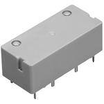
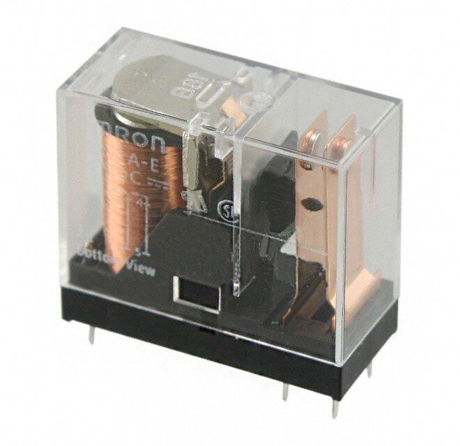
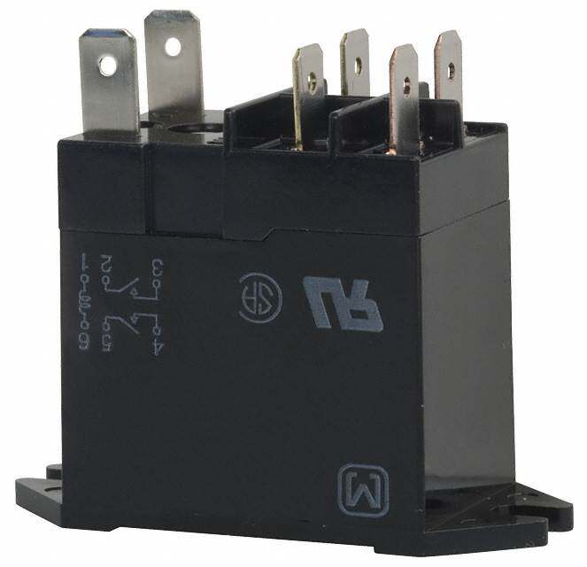
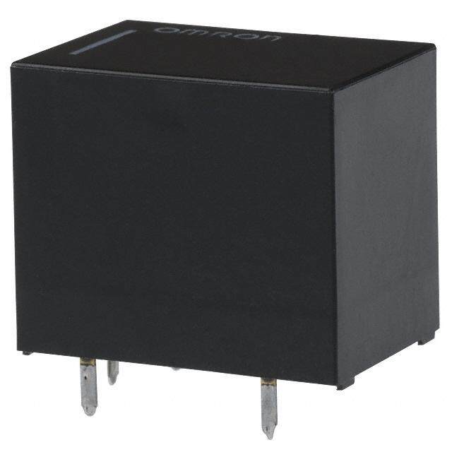
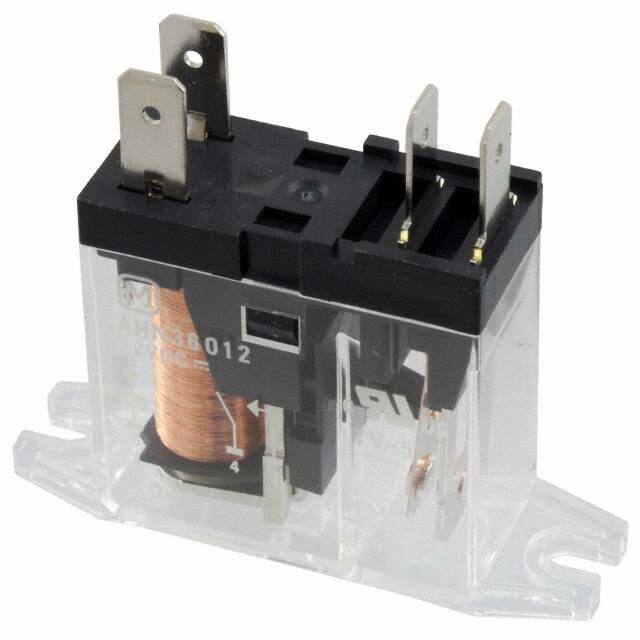
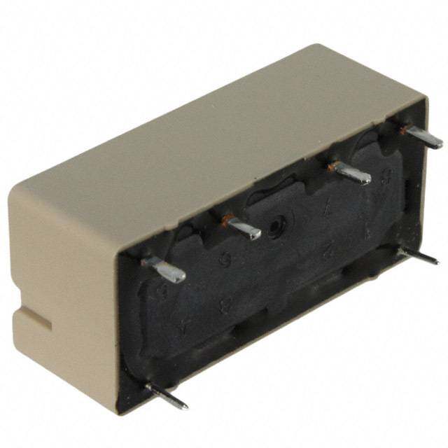
ICGOO电子元器件商城为您提供ST2-DC5V-F由Panasonic Corporation设计生产,在icgoo商城现货销售,并且可以通过原厂、代理商等渠道进行代购。 ST2-DC5V-F价格参考¥询价-¥询价。Panasonic CorporationST2-DC5V-F封装/规格:功率继电器,高于 2 A, 通用 继电器 DPST-NO(2 Form A) 5VDC 线圈 通孔。您可以下载ST2-DC5V-F参考资料、Datasheet数据手册功能说明书,资料中有ST2-DC5V-F 详细功能的应用电路图电压和使用方法及教程。
Panasonic Electric Works(现为 Panasonic Industrial Devices)生产的功率继电器型号 ST2-DC5V-F,其额定电流为 3 A,适用于直流 5V 控制电压。该型号的功率继电器广泛应用于以下场景:

 1. 工业自动化设备
   - PLC 控制系统:用于控制工厂自动化生产线中的电机、电磁阀或其他负载设备。
   - 传感器信号切换:在工业环境中,用于切换不同类型的传感器信号(如温度、压力或位置传感器)。
   - 机器人控制:作为开关元件,控制机器人关节电机或辅助设备的通断。

 2. 家用电器
   - 空调和冰箱:用于压缩机启动/停止控制或风扇电机的切换。
   - 洗衣机和烘干机:控制水阀、加热元件或电机的工作状态。
   - 电热水器:实现加热电路的通断控制。

 3. 照明系统
   - LED 照明控制:用于大功率 LED 灯具的开关控制,尤其是在智能照明系统中。
   - 舞台灯光:切换不同的灯光回路,满足演出需求。

 4. 汽车电子
   - 电动车窗和座椅调节:控制电机的运行。
   - 车载音响系统:用于音频信号的切换或放大器电源控制。
   - 报警系统:实现报警信号的触发或切断。

 5. 通信设备
   - 基站电源管理:用于切换备用电池或主电源。
   - 网络设备控制:控制路由器、交换机等设备的电源通断。

 6. 医疗设备
   - 监护仪和诊断设备:用于控制内部电路的切换或外部设备的连接。
   - 呼吸机和输液泵:控制电机或电磁阀的运行。

 7. 安防系统
   - 门禁控制系统:用于控制电磁锁或电动门的开启与关闭。
   - 监控摄像头:切换摄像头电源或控制云台电机。

 特点总结
- 高可靠性:ST2-DC5V-F 具有长寿命触点,适合频繁切换的应用场景。
- 小型化设计:适合空间有限的设备安装。
- 宽工作温度范围:适应各种恶劣环境下的应用需求。

该型号的继电器凭借其稳定的性能和较高的电流承载能力,在需要可靠电气切换的场景中表现出色。
| 参数 | 数值 |
| 产品目录 | |
| 描述 | RELAY GENERAL PURPOSE DPST 8A 5V通用继电器 8A 5VDC DPST NON-LATCHING PCB |
| 产品分类 | |
| 品牌 | Panasonic Electric Works |
| 产品手册 | |
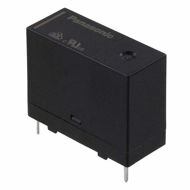
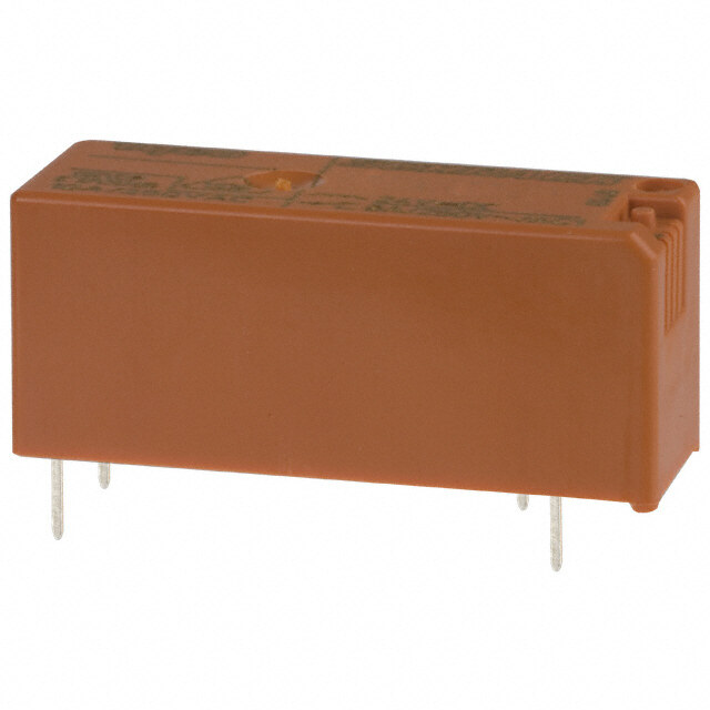
| 产品图片 |
|
| rohs | 符合RoHS无铅 / 符合限制有害物质指令(RoHS)规范要求 |
| 产品系列 | 通用继电器,Panasonic Industrial Devices ST2-DC5V-FST |
| mouser_ship_limit | 该产品可能需要其他文件才能进口到中国。 |
| 数据手册 | |
| 产品型号 | ST2-DC5V-F |
| 产品 | Power Relays |
| 产品目录绘图 |
|
| 产品目录页面 | |
| 产品种类 | 通用继电器 |
| 关闭电压(最小值) | 0.5 VDC |
| 其它名称 | 255-2848 |
| 其它有关文件 | |
| 功耗 | 240 mW |
| 包装 | 管件 |
| 商标 | Panasonic Industrial Devices |
| 安装类型 | 通孔 |
| 安装风格 | Through Hole |
| 导通电压(最大值) | 4 VDC |
| 封装 | Bulk |
| 工作时间 | 15ms |
| 工作温度 | -40°C ~ 60°C |
| 工厂包装数量 | 50 |
| 开关电压 | 380VAC,250VDC - 最小值 |
| 标准包装 | 50 |
| 特性 | 密封式 - 全部 |
| 相关产品 | /product-detail/zh/ST-PS/255-1294-ND/275461/product-detail/zh/ST-SS/255-2253-ND/649237 |
| 端子类型 | PC 引脚 |
| 端接类型 | Solder Pin |
| 类型 | Polarized |
| 线圈功率 | 240 mW |
| 线圈电压 | 5VDC |
| 线圈电流 | 47.6mA |
| 线圈电阻 | 105 欧姆 |
| 线圈端接 | Solder Pin |
| 线圈类型 | 无锁存 |
| 继电器类型 | 通用 |
| 触头外形 | DPST(2 A 型) |
| 触头材料 | 银锡氧化物(AgSnO) |
| 触点形式 | DPST (2 Form A) |
| 触点材料 | Silver Tin Oxide |
| 触点端接 | Pin |
| 释放时间 | 10ms |
| 额定接触(电流) | 8A |


- 商务部:美国ITC正式对集成电路等产品启动337调查
- 曝三星4nm工艺存在良率问题 高通将骁龙8 Gen1或转产台积电
- 太阳诱电将投资9.5亿元在常州建新厂生产MLCC 预计2023年完工
- 英特尔发布欧洲新工厂建设计划 深化IDM 2.0 战略
- 台积电先进制程称霸业界 有大客户加持明年业绩稳了
- 达到5530亿美元!SIA预计今年全球半导体销售额将创下新高
- 英特尔拟将自动驾驶子公司Mobileye上市 估值或超500亿美元
- 三星加码芯片和SET,合并消费电子和移动部门,撤换高东真等 CEO
- 三星电子宣布重大人事变动 还合并消费电子和移动部门
- 海关总署:前11个月进口集成电路产品价值2.52万亿元 增长14.8%
PDF Datasheet 数据手册内容提取
ST VDE 1a1b/2a 8A polarized power ST RELAYS relays 2.High switching capability 6.Automatic cleaning possible High contact pressure, low contact The sealed design means that these bounce, and forced separation relays can undergo immersion in structure that radically improves automatic washing systems and are resistance to contact welding suitable for automatic soldering. Even (1 Form A 1 Form B type equivalent to in difficult environments, the contacts TV-3). Strong against lamp inductive remain reliable. loads, maximum switching capacity 7.Easy to design PC board patterns has reached 3,040 VA (8A 380V AC). Features 4/10 dual-in-line terminals. 3.High breakdown voltage – Optimal Because the lead spacing has a pitch for control in 250 V power circuits greater than 7.54 mm .297 inch, RoHS compliant High breakdown voltage has been designers can make easy adjustments achieved. Between contacts and coil of with the width of the land size. This, 3,750 Vrms; Surge breakdown voltage along with the large insulation between coil and contact of 6,000 V, distance, simplifies the drawing of PC and between open contacts of 1,200 board patterns. Vrms mean that these relays are 8.To improve soldering efficiency, suitable even for 250 V power circuit preapplication of solder to the control. terminals is recommended. 4.Improved stability 9.Sockets are available. Conforms to all types of safety FEATURES standards. 1.Even with small form factor, Insulating distance of more than 3 mm sensitive enough for direct IC- secured. Complies with Japan driving Electrical Appliance and Material The dimensions of this high-density 4- Safety Law requirements for operating gap balanced armature are 31 mm × 200 V power supply circuits, and 14 mm × 11 mm 1.220 inch × .551 inch conforms with UL, CSA and VDE × .433 inch. Despite this small size, standards. high sensitivity is achieved by a 5.Latching types available mechanism that incorporates high- In addition to single side stable types, efficiency polarized magnetic circuits convenient 2 coil latching types with along with our exclusive spring memory functions are also available. alignment method. With an minimum Moreover, we offer 2 Form A operating power of about 150 mW, specifications which, with double pole nominal operating power of 240 mW, switching for applications such as 250 this relay can be directly driven by V power circuit switching, can enable transistor or chip controllers. safer designs. ORDERING INFORMATION ST F Contact arrangement 1: 1 Form A 1 Form B 2: 2 Form A Operating function Nil:Single side stable L2:2 coil latching Nominal coil voltage DC 3, 5, 6, 9, 12, 24, 48 V Contact material F: AgSnO2 type contact Note:Certified by UL, CSA, VDE and SEV ASCTB210E 201202-T Panasonic Corporation Automation Controls Business Unit industrial.panasonic.com/ac/e/
ST TYPES Single side stable 2 coil latching Contact arrangement Nominal coil voltage Part No. Part No. 3V DC ST1-DC3V-F ST1-L2-DC3V-F 5V DC ST1-DC5V-F ST1-L2-DC5V-F 6V DC ST1-DC6V-F ST1-L2-DC6V-F 1 Form A 1 Form B 9V DC ST1-DC9V-F ST1-L2-DC9V-F 12V DC ST1-DC12V-F ST1-L2-DC12V-F 24V DC ST1-DC24V-F ST1-L2-DC24V-F 48V DC ST1-DC48V-F ST1-L2-DC48V-F 3V DC ST2-DC3V-F ST2-L2-DC3V-F 5V DC ST2-DC5V-F ST2-L2-DC5V-F 6V DC ST2-DC6V-F ST2-L2-DC6V-F 2 Form A 9V DC ST2-DC9V-F ST2-L2-DC9V-F 12V DC ST2-DC12V-F ST2-L2-DC12V-F 24V DC ST2-DC24V-F ST2-L2-DC24V-F 48V DC ST2-DC48V-F ST2-L2-DC48V-F Standard packing: Carton: 50 pcs.; Case: 500 pcs. * For sockets, see page 113. RATING 1. Coil data 1) Single side stable Nominal operating Nominal coil Pick-up voltage Drop-out voltage Coil resistance Nominal operating Max. applied voltage voltage (at 20°C 68°F) (at 20°C 68°F) [±10%] c(autr r2e0n°tC 68°F) [±10%] (at 20°C 68°F) power (at 20°C 68°F) 3V DC 75mA 38Ω 5V DC 47mA 105Ω 6V DC 80%V or less of 10%V or more of 40mA 150Ω 9V DC nominal voltage nominal voltage 25mA 360Ω 240mW 150%V of nominal voltage 12V DC (Initial) (Initial) 20mA 600Ω 24V DC 10mA 2,400Ω 48V DC 4.7mA 9,000Ω 2) 2 coil latching Nominal operating Coil resistance Nominal operating Novmoilntaagl ecoil (aSt e2t0 v°Col t6a8g°eF ) (Raet s2e0t° Cvo 6lt8a°gFe) [±10%] c(autr r2e0n°tC 68°F) [±10%] (at 20°C 68°F) power Ma(xa. ta 2p0p°liCe d6 8vo°Flt)age Set coil Reset coil Set coil Reset coil Set coil Reset coil 3V DC 75mA 75mA 40Ω 40Ω 5V DC 45mA 45mA 110Ω 110Ω 6V DC 80%V or less of 80%V or less of 37.5mA 37.5mA 155Ω 155Ω 9V DC nominal voltage nominal voltage 25mA 25mA 360Ω 360Ω 240mW 240mW 150%V of nominal voltage 12V DC (Initial) (Initial) 18.8mA 18.8mA 640Ω 640Ω 24V DC 10mA 10mA 2,400Ω 2,400Ω 48V DC 4.7mA 4.7mA 10,200Ω 10,200Ω ASCTB210E 201202-T Panasonic Corporation Automation Controls Business Unit industrial.panasonic.com/ac/e/
ST 2. Specifications Characteristics Item Specifications Arrangement 1 Form A 1 Form B, 2 Form A Contact Contact material Au-flashed AgSnO2 type Contact resistance (Initial) Max. 30 mΩ (By voltage drop 6 V DC 1A) Max. switching power (resistive load) 3,040 VA, 150 W Max. switching voltage 380 V AC, 250 V DC Max. switching current 8 A Rating Minimum operating power 150mW (Single side stable, 2 coil latching) Nominal operating power 240mW (Single side stable, 2 coil latching) Min. switching capacity (Reference value)*1 100 mA 5V DC Insulation resistance (Initial) Min. 1,000MΩ (at 500V DC) (at 25°C, 50% relative humidity) Measurement at same location as “Breakdown voltage” section. Between open contacts 1,200 Vrms for 1 min. (Detection current: 10 mA) Breakdown voltage Between contact sets 2,000 Vrms for 1 min. (Detection current: 10 mA) (Initial) Between contact and coil 3,750 Vrms for 1 min. (Detection current: 10 mA) Electrical Surge breakdown voltage (Initial)*2 6,000 V (Between contact and coil) characteristics Operate time [Set time] (at 20°C 68°F) Max. 15 ms [Max. 15 ms] (Nominal coil voltage applied to the coil, excluding contact bounce time.) Release time [Reset time] (at 20°C 68°F) Max. 10 ms [Max. 15 ms] (Nominal coil voltage applied to the coil, excluding contact bounce time.) (without diode) Temperature rise (coil) (at 60°C 140°F) Max. 55°C (By resistive method, nominal voltage applied to the coil; contact carrying current: 8A.) Functional Min. 196 m/s2 (Half-wave pulse of sine wave: 11 ms; detection time: 10µs.) Shock resistance Mechanical Destructive Min. 980 m/s2 (Half-wave pulse of sine wave: 6 ms.) characteristics Functional 10 to 55 Hz at double amplitude of 2 mm (Detection time: 10µs.) Vibration resistance Destructive 10 to 55 Hz at double amplitude of 3 mm Mechanical Min. 107 (at 180 times/min.) Expected life Electrical Min. 105 (8 A 250 V AC resistive) (ON : OFF = 1 s : 5 s) Ambient temperature: –40°C to +60°C –40°F to +140°F; Conditions for operation, transport and storage*3 Conditions Humidity: 5 to 85% R.H. (Not freezing and condensing at low temperature) Max. operating speed 30 cps Unit weight Approx. 10g .353 oz Notes:*1.This value can change due to the switching frequency, environmental conditions, and desired reliability level, therefore it is recommended to check this with the actual load. *2.Wave is standard shock voltage of ±1.2×50µs according to JEC-212-1981 *3.The upper limit of the ambient temperature is the maximum temperature that can satisfy the coil temperature rise value. Refer to Usage, transport and storage conditions in NOTES. REFERENCE DATA 1. Max. switching power 2. Coil temperature rise 3. Influence of adjacent mounting 10 100 40 AC resistive load 5 90 30 AC inductive C 80 % Current, A0.215 l(ocaoDldosCϕad= r0e.s4i)stive °Temperature rise, 76540000 Contact current 8A 0A Rated of change, -2110000 PDircokp--uopu vt ovlotaltgaege DC inductive 30 load -20 (L/R=40ms) 20 0.2 10 -30 0 -40 0 20 50 100 200300 600 1000 0.2 0.4 0.6 0.8 1.0 1.2 5 10 15 20 Voltage, V Coil operating power, W Inter-relay distance, mm ASCTB210E 201202-T Panasonic Corporation Automation Controls Business Unit industrial.panasonic.com/ac/e/
ST DIMENSIONS (mm inch) The CAD data of the products with a CAD Data mark can be downloaded from: http://industrial.panasonic.com/ac/e/ CAD Data External dimensions PC board pattern (Bottom view) 31.0 14 2 coil latching 1.220 .551 types only. 11.0 .433 0.3 .012 3.5.138 2.54 .100 7.62 10.16 7.62 10.16 .300 .400 .300 .400 8-1.4 dia. .013.09 0.3.001.62 dia..024 dia. 8-.055 dia. 2.1.5040 Tolerance: ±0.1 ±.004 1 2 3 4 8 7 6 5 0.5 .020 1.0 1.0 .039 .039 General tolerance: ±0.5 ±.020 Schematic (Bottom view) Single side stable 2 coil latching 1 Form A 1 Form B 2 Form A 1 Form A 1 Form B 2 Form A 1 4 1 4 1 2 3 4 1 2 3 4 – + – + – + + – – + + – 8 7 6 5 8 7 6 5 8 7 6 5 8 7 6 5 (Deenergized condition) (Reset condition) SAFETY STANDARDS UL/C-UL (Recognized) CSA (Certified) VDE (Certified) TV rating (UL/CSA) SEV File No. Contact rating File No. Contact rating File No. Contact rating File No. Rating File No. Contact rating E43028 8A 250V AC LR26550 8A 250V AC 1017 8A 250V AC (cosφ=1.0) UL: E43028 98-1 10289 8A 380V AC 1/4HP 125, 250V AC etc. 1/4HP 125, 250V AC 4A 250V AC (cosφ=0.4) CSA: LR26550 — 5A 30V DC 5A 30V DC 5A 30V DC NOTES 1. PC board patterns for 2 coil latching 2. Soldering should be done under the 3. When using, please be aware that types following conditions: the a contact and b contact sides of 1 When applying relays in power supply 1) Form A and 1 Form B types may go on operation circuits for finished products 250°C 482°F within 10s simultaneously at operate time and regulated by the Electrical Appliance and 300°C 572°F within 5s release time. Material Safety Law, use the pattern 350°C 662°F within 3s shown below. 2) For automatic cleaning, the boiling method is recommended. Avoid ultrasonic cleaning which subjects the relays to high frequency vibrations, which may cause the contacts to stick. It is recommended that a fluorinated Terminal No. 1 2 3 4 hydrocarbon or other alcoholic solvents be used. For Cautions for Use. ASCTB210E 201202-T Panasonic Corporation Automation Controls Business Unit industrial.panasonic.com/ac/e/
Mouser Electronics Authorized Distributor Click to View Pricing, Inventory, Delivery & Lifecycle Information: P anasonic: ST2-DC12V ST2-DC48V ST1-DC48V ST2-L2-DC5V ST1-DC5V ST2-DC5V ST1-DC12V ST1-DC24V ST2- DC24V ST-PS ST-SS ST2-DC12V-F ST1-DC12V-F ST1-L2-DC12V-F ST2-DC5V-F ST1-DC24V-F ST1-L2-DC5V- F ST2-DC24V-F ST1-DC5V-F ST1-L2-DC24V-F ST2-L2-DC5V-F ST1-DC48V-F ST1-DC3V-F ST2-DC3V-F ST2- DC48V-F ST2-DC9V-F ST2-L2-DC12V-F ST1-DC3V ST1-DC6V ST1-DC9V ST1-L2-DC12V ST1-L2-DC24V ST1- L2-DC3V ST1-L2-DC48V ST1-L2-DC5V ST1-L2-DC6V ST1-L2-DC9V ST2-DC3V ST2-DC6V ST2-DC9V ST2-L2- DC12V ST2-L2-DC24V ST2-L2-DC3V ST2-L2-DC48V ST2-L2-DC6V ST2-L2-DC9V ST2-L-DC12V ST2-L-DC3V ST2-L-DC5V ST2-L2-DC48V-F ST1-L2-DC3V-F ST1-L2-DC9V-F ST1-L2-DC6V-F ST1-L2-DC48V-F ST2-L2- DC24V-F