ICGOO在线商城 > 继电器 > 功率继电器,高于 2 A > G6C-2114P-US-DC12
 Datasheet下载
- 型号: G6C-2114P-US-DC12
- 制造商: Omron Electronics LLC
- 库位|库存: xxxx|xxxx
- 要求:
| 数量阶梯 | 香港交货 | 国内含税 |
| +xxxx | $xxxx | ¥xxxx |
查看当月历史价格
查看今年历史价格
G6C-2114P-US-DC12产品简介:
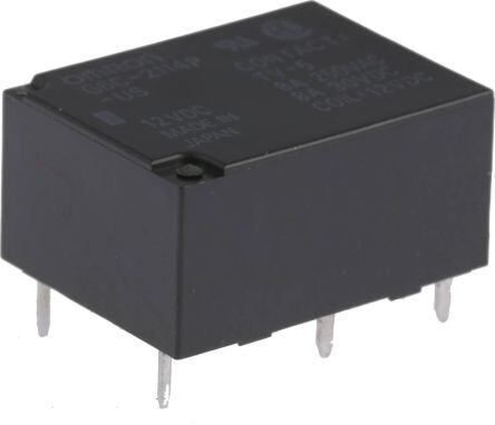
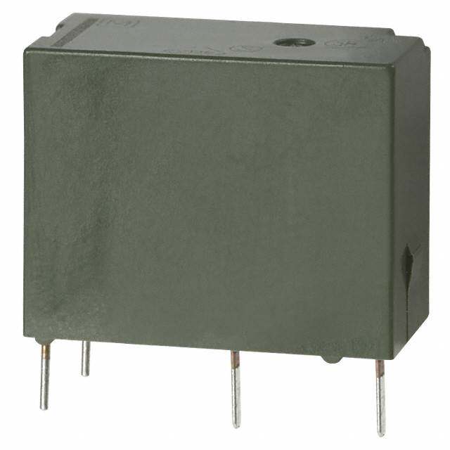
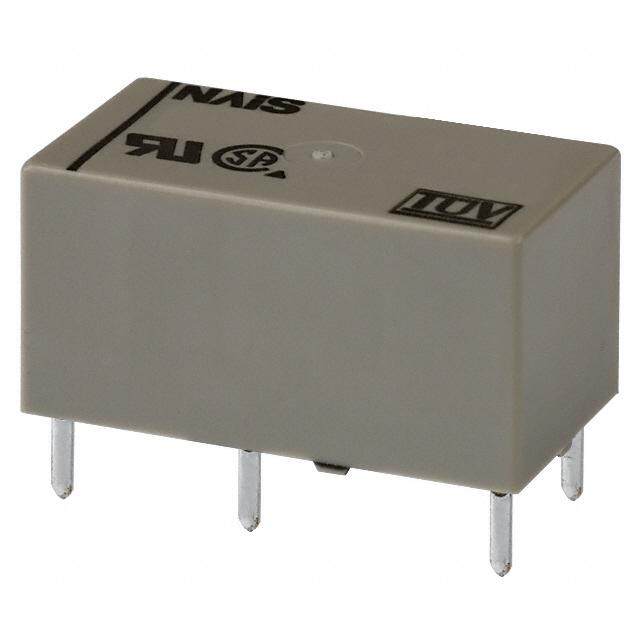
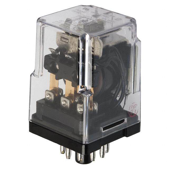
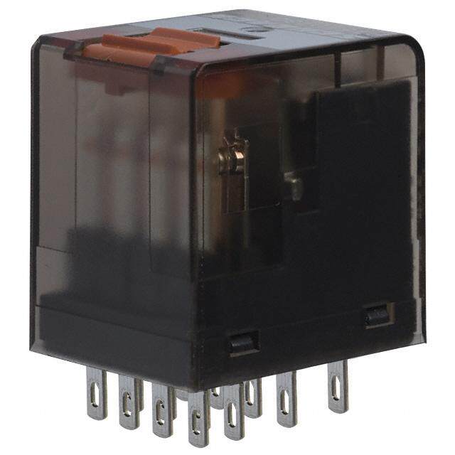
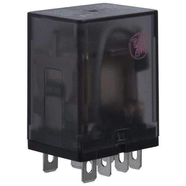
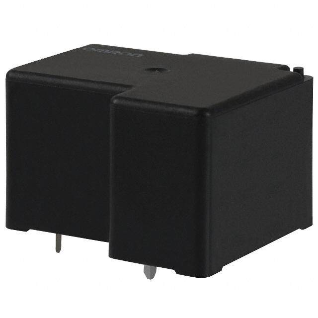
ICGOO电子元器件商城为您提供G6C-2114P-US-DC12由Omron Electronics LLC设计生产,在icgoo商城现货销售,并且可以通过原厂、代理商等渠道进行代购。 G6C-2114P-US-DC12价格参考¥36.10-¥36.10。Omron Electronics LLCG6C-2114P-US-DC12封装/规格:功率继电器,高于 2 A, 通用 继电器 DPST-NO/NC(1 Form A,1 From B) 12VDC 线圈 通孔。您可以下载G6C-2114P-US-DC12参考资料、Datasheet数据手册功能说明书,资料中有G6C-2114P-US-DC12 详细功能的应用电路图电压和使用方法及教程。
Omron(欧姆龙)G6C-2114P-US-DC12 是一款由欧姆龙电子有限公司EMC部门生产的功率继电器,额定电流高于2A。该型号继电器采用直流12V线圈驱动,具备良好的负载切换能力,适用于多种工业与自动化控制场景。

其典型应用场景包括:

1. 工业自动化设备:用于控制电机、电磁阀、加热器等大功率负载的通断,广泛应用于PLC控制系统中。
2. 电源管理系统:在UPS(不间断电源)、电池管理系统(BMS)中作为开关元件,实现对电源的自动切换和保护。
3. 暖通空调系统(HVAC):控制压缩机、风扇或加热元件等高电流设备,实现温度自动调节。
4. 安防与楼宇控制系统:用于门禁系统、照明控制、报警装置中,实现远程控制与自动化操作。
5. 测试与测量设备:在自动测试设备(ATE)中用作信号或电源切换开关,提高测试效率和安全性。

该继电器具有较高的可靠性和较长的机械寿命,适合在较宽温度范围内稳定工作,是工业控制领域中常用的电气元件之一。
| 参数 | 数值 |
| 产品目录 | |
| 描述 | RELAY GEN PURPOSE DPST 8A 12V通用继电器 Power PCB Relay SPST-NO + -NC 12VDC |
| 产品分类 | |
| 品牌 | Omron Electronics |
| 产品手册 | |
| 产品图片 |
|
| rohs | 符合RoHS无铅 / 符合限制有害物质指令(RoHS)规范要求 |
| 产品系列 | 通用继电器,Omron Electronics G6C-2114P-US-DC12G6C |
| mouser_ship_limit | 该产品可能需要其他文件才能进口到中国。 |
| 数据手册 | |
| 产品型号 | G6C-2114P-US-DC12 |
| 产品 | Low Profile Relays |
| 产品培训模块 | http://www.digikey.cn/PTM/IndividualPTM.page?site=cn&lang=zhs&ptm=25458 |
| 产品目录绘图 |
|
| 产品目录页面 | |
| 产品种类 | 通用继电器 |
| 关闭电压(最小值) | 1.2 VDC |
| 其它名称 | G6C 1120H |
| 其它有关文件 | |
| 功耗 | 200 mW |
| 包装 | 散装 |
| 商标 | Omron Electronics |
| 安装类型 | 通孔 |
| 安装风格 | Through Hole |
| 导通电压(最大值) | 8.4 VDC |
| 工作时间 | 10ms |
| 工作温度 | -25°C ~ 70°C |
| 工厂包装数量 | 100 |
| 开关电压 | 380VAC,125VDC - 最小值 |
| 标准包装 | 100 |
| 特性 | 密封式 - 全部 |
| 相关产品 | /product-detail/zh/P6C-06P/Z126-ND/307646 |
| 端子类型 | PC 引脚 |
| 类型 | Miniature |
| 系列 | G6C |
| 线圈功率 | 200 mW |
| 线圈电压 | 12 V |
| 线圈电流 | 16.7 mA |
| 线圈电阻 | 720 Ohms |
| 线圈类型 | Non-Latching |
| 继电器类型 | 通用 |
| 触头外形 | DPST-NO/NC(1 Form A,1 Form B) |
| 触头材料 | 银合金,无镉 |
| 触点形式 | SPST (1 Form A), SPST (1 Form B) |
| 触点材料 | Silver Alloy |
| 触点端接 | PCB |
| 释放时间 | 10ms |
| 零件号别名 | 375243 G6C2114PUS12DC G6C2114PUSDC12NC |
| 额定接触(电流) | 8A |


P-US%20Circuit.jpg)
P-US%20Footprint.jpg)
114P-US.jpg)


- 商务部:美国ITC正式对集成电路等产品启动337调查
- 曝三星4nm工艺存在良率问题 高通将骁龙8 Gen1或转产台积电
- 太阳诱电将投资9.5亿元在常州建新厂生产MLCC 预计2023年完工
- 英特尔发布欧洲新工厂建设计划 深化IDM 2.0 战略
- 台积电先进制程称霸业界 有大客户加持明年业绩稳了
- 达到5530亿美元!SIA预计今年全球半导体销售额将创下新高
- 英特尔拟将自动驾驶子公司Mobileye上市 估值或超500亿美元
- 三星加码芯片和SET,合并消费电子和移动部门,撤换高东真等 CEO
- 三星电子宣布重大人事变动 还合并消费电子和移动部门
- 海关总署:前11个月进口集成电路产品价值2.52万亿元 增长14.8%

PDF Datasheet 数据手册内容提取
G6C PCB Power Relay Miniature High Capacity Relays with SPST-NO 10A and SPST-NO + SPST-NC 8A •SPST-NO 10A and SPST-NO + SPST-NC 8A for power switching and output that satisfy the needs for space-saving. (cid:129)Small High-capacity Relays Compact: 20 × 15 × 10 mm (L × W × H). (cid:129)Low power consumption: 200 mW. (cid:129)Ultrasonically cleanable models is available. (cid:129)Exclusive P6C model for sockets is now available. RoHS Compliant ■Model Number Legend ■Application Examples G6C-@-@@@@@-@-@-@-@ Ideal for output applications of control 1 2 3 4 5 6 7 8 9 equipments G 6 1. Relay Function 6. Contact Material C None: Single-side stable None: Standard (Ag-alloy (Cd free)) U : Single-winding latching FD : AgSnIn Contacts K : Double-winding latching (Suitable for DC inductive load 2. Contact Form with high inrush current) 11: SPST-NO (1a) 7. Approved Standards 21: SPST-NO (1a) + SPST-NC (1b) US: UL/CSA 3. Contact Type 8. Washability 1: Single None: Standard model 4. Enclosure rating (not compatible with ultrasonically 4: Fully sealed cleanable models) 7: Flux protection U : For ultrasonically cleanable 5. Terminal Shape 9. Mounting P: PCB terminals None: Mounted directly to PCB Socket mounting Terminals P6C: Mounted to Socket C: Self-clinching PCB 1
G6C PCB Power Relay ■Ordering Information ●Standard Models (UL, CSA certified) Relay Function Single-side stable Single-winding latching Double-winding latching Minimun Enclosure Rated coil Rated coil Rated coil packing rating Contact form Terminals Model voltage Model voltage Model voltage unit 3 VDC 3 VDC 3 VDC 5 VDC 5 VDC 5 VDC G6C-1117P-US 6 VDC G6CU-1117P-US − G6CK-1117P-US 6 VDC 12 VDC 12 VDC 12 VDC Straight PCB 24 VDC 24 VDC 24 VDC 5 VDC 5 VDC − SPST-NO (1a) G6C-1117P-FD-US 12 VDC G6CU-1117P-FD-US 12 VDC G6CK-1117P-FD-US 12 VDC 24 VDC 24 VDC − 3 VDC − − Self-clinching G6C-1117C-US 5 VDC − − G6CK-1117C-US − PCB 12 VDC − 12 VDC 24 VDC − 24 VDC Flux 100 pcs/ 3 VDC 3 VDC 3 VDC protection tray 5 VDC 5 VDC 5 VDC G6C-2117P-US 6 VDC G6CU-2117P-US 6 VDC G6CK-2117P-US 6 VDC 12 VDC 12 VDC 12 VDC Straight PCB 24 VDC 24 VDC 24 VDC 5 VDC 5 VDC 5 VDC G SPST-NO (1a) + G6C-2117P-FD-US 12 VDC G6CU-2117P-FD-US 12 VDC G6CK-2117P-FD-US − 6 SPST-NC (1b) C 24 VDC 24 VDC 24 VDC 3 VDC − 3 VDC 5 VDC 5 VDC 5 VDC Self-clinching G6C-2117C-US 6 VDC G6CU-2117C-US − G6CK-2117C-US − PCB 12 VDC 12 VDC 12 VDC 24 VDC − 24 VDC Relay Function Single-side stable Single-winding latching Double-winding latching Minimun Enclosure Rated coil Rated coil Rated coil packing rating Contact form Terminals Model voltage Model voltage Model voltage unit 3 VDC 3 VDC 3 VDC 5 VDC 5 VDC 5 VDC G6C-1114P-US 6 VDC G6CU-1114P-US 6 VDC G6CK-1114P-US 6 VDC 12 VDC 12 VDC 12 VDC Straight PCB 24 VDC 24 VDC 24 VDC 5 VDC 5 VDC 5 VDC SPST-NO (1a) G6C-1114P-FD-US 12 VDC G6CU-1114P-FD-US 12 VDC G6CK-1114P-FD-US 12 VDC 24 VDC 24 VDC 24 VDC 3 VDC − 3 VDC Self-clinching 5 VDC − 5 VDC G6C-1114C-US G6CU-1114C-US G6CK-1114C-US PCB 12 VDC 12 VDC 12 VDC 24 VDC − 24 VDC Fully 100 pcs/ 3 VDC 3 VDC 3 VDC sealed tray 5 VDC 5 VDC 5 VDC G6C-2114P-US 6 VDC G6CU-2114P-US 6 VDC G6CK-2114P-US 6 VDC 12 VDC 12 VDC 12 VDC Straight PCB 24 VDC 24 VDC 24 VDC 5 VDC 5 VDC − SPST-NO (1a) + G6C-2114P-FD-US 12 VDC G6CU-2114P-FD-US 12 VDC G6CK-2114P-FD-US − SPST-NC (1b) 24 VDC 24 VDC 24 VDC 3 VDC − − 5 VDC 5 VDC 5 VDC Self-clinching G6C-2114C-US 6 VDC G6CU-2114C-US − G6CK-2114C-US 6 VDC PCB 12 VDC − 12 VDC 24 VDC − 24 VDC Note.When ordering, add the rated coil voltage to the model number. Example: G6C-1117P-US DC3 Rated coil voltage However, the notation of the coil voltage on the product case as well as on the packing will be marked as @@ VDC. 2
G6C PCB Power Relay ●Ultrasonically Cleanable Models (UL, CSA certified) Relay Function Single-side stable Single-winding latching Double-winding latching Minimun Enclosure Rated coil Rated coil Rated coil packing rating Contact form Terminals Model voltage Model voltage Model voltage unit 3 VDC − − 5 VDC 5 VDC 5 VDC Straight PCB G6C-1114P-US-U 6 VDC G6CU-1114P-US-U − G6CK-1114P-US-U − SPST-NO (1a) 12 VDC 12 VDC 12 VDC 24 VDC − 24 VDC Fully sealed Self-PclCinBching G6C-1114C-US-U 1224 VVDDCC − −− − −− 100 pcs/ tray 5 VDC − 5 VDC Straight PCB G6C-2114P-US-U 12 VDC − − G6CK-2114P-US-U 12 VDC SPST-NO (1a) + 24 VDC − − SPST-NC (1b) 5 VDC − − Self-clinching G6C-2114C-US-U 12 VDC − − − − PCB 24 VDC − − Note.When ordering, add the rated coil voltage to the model number. Example: G6C-1114P-US-U DC3 Rated coil voltage However, the notation of the coil voltage on the product case as well as on the packing will be marked as @@ VDC. ●Connecting Sockets (Sold Separately) Applicable relays Model Minimun packing unit G G6C-2114P-US-P6C 6 G6C-2117P-US-P6C C G6C-1114P-US-P6C G6C-1117P-US-P6C P6C-06P G6CU-2114P-US-P6C G6CU-2117P-US-P6C 20 pcs/tube G6CU-1114P-US-P6C G6CU-1117P-US-P6C G6CK-2114P-US-P6C G6CK-2117P-US-P6C P6C-08P G6CK-1114P-US-P6C G6CK-1117P-US-P6C Removal Tool P6B-Y1 1 Hold-down Clips P6B-C2 Note 1.Use the G6C-@@@@P-US-P6C to mount to a P6C Socket. 2.When using by combining sockets, the rated current will be 5A due to its rated switching current. 3
G6C PCB Power Relay ■Ratings Coil: 1-Pole, Single-side Stable Type (Including models for ultrasonically cleanable) Item Must operate Must release Max. Rated Coil Power voltage voltage voltage current resistance consumption (V) (V) (V) (mA) (Ω) (mW) Rated voltage % of rated voltage 3 VDC 67 45 5 VDC 40 125 160% 6 VDC 33.3 180 70% max. 10% min. Approx. 200 (at 23°C) 12 VDC 16.7 720 24 VDC 8.3 2,880 Coil: Single-winding Latching Type (Including models for ultrasonically cleanable) Item Must set Must reset Max. Power consumption Rated Coil voltage voltage voltage current resistance (V) (V) (V) Set coil Reset coil (mA) (Ω) (mW) (mW) Rated voltage % of rated voltage 3 VDC 67 45 5 VDC 40 125 160% 6 VDC 33.3 180 70% max. 70% max. 200 200 (at 23°C) 12 VDC 16.7 720 24 VDC 8.3 2,880 Coil: Double-winding Latching Type (Including models for ultrasonically cleanable) Item Rated current (mA) Coil resistance (Ω) Must set Must reset Max. Power consumption G voltage voltage voltage 6 Set coil Reset coil Set coil Reset coil (V) (V) (V) Set coil Reset coil C (mW) (mW) Rated voltage % of rated voltage 3 VDC 93.5 93.5 32.1 32.1 5 VDC 56.0 56.0 89.3 89.3 130% 6 VDC 46.7 46.7 129 129 70% max. 70% max. 280 280 (at 23°C) 12 VDC 23.3 23.3 514 514 24 VDC 11.7 11.7 2,056 2,056 Note 1.The rated current and coil resistance are measured at a coil temperature of 23°C with a tolerance of ±10%. 2.The operating characteristics are measured at a coil temperature of 23°C. 3.The “Max. voltage” is the maximum voltage that can be applied to the relay coil. Contact Contact Form SPST-NO (1a) SPST-NO (1a) + SPST-NC (1b) Inductive load Inductive load Resistive load (cosφ = 0.4; L/R = 7 ms) Resistive load (cosφ = 0.4; L/R = 7 ms) Rated load 10 A (8 A) at 250 VAC 5 A (5 A) at 250 VAC 8 A (8 A) at 250 VAC 3.5 A (3.5 A) at 250 VAC Item 10 A (10 A) at 30 VDC 5 A (5 A) at 30 VDC 8 A (8 A) at 30 VDC 3.5 A (3.5 A) at 30 VDC Contact type Single Contact material Ag-Alloy (Cd free) Rated carry current 10 A (10 A) 8 A (8 A) Max. switching voltage 380 VAC, 125 VDC Max. switching current 10 A (10 A) 8 A (8 A) Note.The values shown in parentheses ( ) are for -FD models only. 4
G6C PCB Power Relay ■Characteristics (Including models for ultrasonically cleanable) Item Classification Single-side Stable Single-winding Latching Double-winding Latching Contact resistance *1 30 mΩ max. Operate (set) time 10 ms max. Release (reset) time 10 ms max. Min. set pulse width − 20 ms (at 23°C) Min. reset pulse width − 20 ms (at 23°C) Between coil and 1,000 MΩ min. contacts Between contacts of the 1,000 MΩ min. Insulation same polarity resistance *2 Between contacts of 1,000 MΩ min. (SPST-NO, SPST-NC) different polarity Between set and reset − − 1,000 MΩ min. coils Between coil and 2,000 VAC 50/60Hz for 1min contacts Between contacts of the 1,000 VAC 50/60Hz for 1min Dielectric same polarity strength Between contacts of 2,000 VAC 50/60Hz for 1min (SPST-NO, SPST-NC) different polarity Between set and reset − − 250 VAC 50/60Hz for coils 1min Vibration Destruction 10 to 55 to 10 Hz, 0.75 mm single amplitude (1.5 mm double amplitude) resistance Malfunction 10 to 55 to 10 Hz, 0.75 mm single amplitude (1.5 mm double amplitude) Shock Destruction 1,000 m/s2 Note.The given values are initial values. resistance Malfunction 100 m/s2 *1. Measurement conditions: 5 VDC, 1 A, voltage Durability Mechanical 50,000,000 operations min. (at 18,000 operations/hr) drop method. Electrical 100,000 operation min. (at 1,800 operations/hr under rated load) *2. Testing conditions: measured with a 500 VDC G Failure rate (P level) (reference value) *3 10 mA at 5 VDC megohmmeter (at 250 VDC between set/reset 6 Ambient operating temperature -25°C to 70°C (with no icing or condensation) coil). C Ambient operating humidity 5% to 85% *3. This value was measured at a switching Weight Approx. 5.6 g frequency of 120 operations/min. ■Engineering Data ●Maximum Switching Capacity G6C-1114@-US G6C-1114@-FD-US G6C-1117@-US G6C-1117@-FD-US A) 50 A) 50 witching current ( 31007 AC resistive load witching current ( 31008 AC resistive load S 5 S 5 3 DC resistive load AC inductive 3 AC inductive load 2 DC resistive load load DC inductive load (cosφ = 0.4) (cosφ = 0.4) 1 (L/R = 7 ms) 1 DC inductive load 0.7 0.7 (L/R = 7 ms) 0.5 0.5 0.3 0.3 0.2 0.2 0.1 0.1 1 3 5 7 10 30 50 100 250 380 1,000 1 3 5 7 10 30 50 100 250 380 1,000 Switching voltage (V) Switching voltage (V) G6C-2114@-US G6C-2114@-FD-US G6C-2117@-US G6C-2117@-FD-US A) 50 A) 50 witching current ( 31008 AC resistive load witching current ( 31008 AC resistive load S 5 S 5 3 3 2 DC resistive load AC inductive 2 AC inductive 1 D(LC/R i n=d 7u cmtivse) load l(ocaodsφ = 0.4) 1 DC resistive load l(ocaodsφ = 0.4) 0.7 0.7 DC inductive load 0.5 0.5 (L/R = 7 ms) 0.3 0.3 0.2 0.2 0.1 0.1 1 3 5 7 10 30 50 100 250 380 1,000 1 3 5 7 10 30 50 100 250 380 1,000 Switching voltage (V) Switching voltage (V) 5
G6C PCB Power Relay ●Durability G6C-1114@-US, G6C-2114@-US G6C-1114@-FD-US, G6C-2114@-FD-US G6C-1117@-US, G6C-2117@-US G6C-1117@-FD-US, G6C-2117@-FD-US 4Durability (× 10 operations)5310005300000 GG3205660 CCV V--D22AC11C11 r 47er@@esiss--iUUtsivtSSieve 3GG205660 CCV V--D11AC11C 11r 47er@@esiss--iUUtsivtSSieve 4Durability (x 10 operations)5310005300000 GG2350660 CCV V--D22AC11C11 r 47er@@esiss--iFFtsiDDvtiev--eUUSSG2G5660CC V--11A11C11 74r@@esG-G---FFiFFs66DDDDtCCiv----UU--eUU11SSSS111147@@ 30 VDC resistive 10 10 53 (GG2(3cL5066o/0 RCCsV φV--D=22 A= C117 C 110 imn 47.i4nd@@s)du)--ucUUtciSSvtieve (3(GG2Lc0566o/ 0RCCsV φV--D=11 A= C117 C11 0 imn 47.i4nd@@s)du)--ucUUtciSSvtieve 53 GG(2(3cL5066o/0 RCCsV φV--D=22 A= C117 C11 0 imn 47.i4nd@@s)du)--ucFFtcDDivti--evUUe SS (2(3GGLc5066o/0 RCCsV φV--D=11 A= C117 C1 10 imn 47.i4nd@@s)du)--ucFFtcDDivti--evUUe SS 1 1 0 1 2 3 4 5 6 7 8 9 10 11 0 1 2 3 4 5 6 7 8 9 10 11 Switching current (A) Switching current (A) ●Ambient Temperature vs. ●Ambient Temperature vs Must Maximum Coil Voltage Operate and Must Release voltages %)200 %)100 Sample: Must operate voltage GC6 Maximum coil voltage (111111864320000000 Operate and Must Release voltages ( 864000 GN5 u6pmCcs-b1e1r4 oPf -RUeSl a ys: Must release mmvmoiaanltxx.a..XgXe Must 20 min. 80 60 0 10 20 23 30 40 50 60 70 80 90 -40 -20 0 20 40 60 80 Ambient temperature (°C) Ambient temperature (°C) Note.The maximum coil voltage refers to the maximum value in a varying range of operating power voltage, not a continuous voltage. ●Shock Malfunction ●Magnetic Interference (between Relays) E(an ceorgnitzaecdt) Y600 D(be c-eonnetargctiz)ed Y600 V) (%) 3 O 6XZ0'0600400400200200 642240000000000 220000 40050066Z0X000' 6XZ00'600440000200200 642240000000000 220000 440000 66ZX0000' Y SXhock directioXn' Change rate on the basis of rated value ( --21012 l1 l2mXmainx.S.ample Y' Unit: m/s2 Y' Unit: m/s2 Z -3 (Mounting pitch) Z' Initial l1=2.54a l1=5.08a l1=7.62a Y' l2=5.08a l2=7.62a l2=10.16a (coil) Sample: G6C-2114P-US DC24V Number of Relays: 6 pcs Test conditions: Shock is applied in ±X, ±Y, and ±Z directions three times each with without energizing the Relays to check the number of malfunctions. Requirement: 100 m/s2 6
G6C PCB Power Relay ■Dimensions Flux Protection Model PCB Mounting Holes Terminal Arrangement/ (Straight PCB) (Bottom View) Internal Connections G6C-@117P (-FD) -US 20 max. 15 max. Tolerance: ±0.1 (Bottom View) (19.9)* (14.9)* 1-pole 10 max. 2.54 0.3 (9.9)* Four, 1.1-dia. holes 1-pole 2.54 3.5 1 3 4 − 0.65<0.7> 0.9<1.0> <00..54> 0.9<1.0> 10.16 7.62 1.11 10.16 + (2.4) 8 * Average value Dimensions in pointed brackets < > are for the Relay mounted to Socket (-P6C). 10.16 7.62 (1.1) Flux Protection Model 2-pole (Self-clinching PCB) 2.54 G6C-@117C-US Six, 1.1-dia. holes 20 max. 15 max. 2-pole (19.9)* (14.9)* 2.54 1 3 4 − 10 max. 0.3 (9.9)* 3.2 3.5 (0.8)* (2.4) 8+ 6 5 (1.0)* 0.65 0.9 0.5 10.16 0.9 1.11 10.16 10.16 7.62 Note:Check carefully the coil G 7.62 (1.1) polarity of the Relay. 6 * Average value C Fully Sealed Model PCB Mounting Holes Terminal Arrangement/ (Straight PCB) 20 max. 15 max. 1-pole (Bottom View) Internal Connections (19.9)* (14.9)* Tolerance: ±0.1 (Bottom View) G6C-@114P (-FD) -US 2.54 Four, 1.1-dia. holes 1-pole 10 max. 0.3 (9.9)* 2.54 1 3 4 − 3.5 0.65<0.7> 0.9<1.0> 0.9<1.0> <00..54> + (2.4) 8 10.16 1.11 10.16 7.62 * Average value 10.16 7.62 Dimensions in pointed brackets < > are (1.1) for the Relay mounted to Socket (-P6C). 2-pole Fully Sealed Model 2.54 (Self-clinching PCB) 20 max. 15 max. Six, 1.1-dia. holes 2-pole G6C-@114C-US (19.9)* (14.9)* 2.54 1 3 4 10 max. − 0.3(9.9)* 3.2 3.5 (0.8)* (1.0)* (2.4) 8+ 6 5 0.65 0.9 0.9 0.5 Note:Check carefully the coil 10.16 7.62 1.11 10.16 10.16 7.62 polarity of the Relay. * Average value (1.1) Note: Orientation marks are indicated as follows: 7
G6C PCB Power Relay Flux Protective PCB Mounting Holes Terminal Arrangement/ Single-winding Latching Model (Bottom View) Internal Connections (Straight PCB) 20 max. 15 max. Tolerance: ±0.1 (Bottom View) (19.9)* (14.9)* G6CU-@117P (-FD) -US 1-pole 10 max. 2.54 0.3 (9.9)* Four, 1.1-dia. holes 1-pole 2.54 3.5 1 3 4 − + 0.65<0.7> 0.9<1.0> 0.5 0.9<1.0> <0.4> SR 10.16 1.11 10.16 + − 7.62 (2.4) 8 * Average value S: Set coil Dimensions in pointed brackets < > 10.16 7.62 R: Reset coil are for the Relay mounted to Socket (-P6C). (1.1) Flux Protective 2-pole Single-winding Latching Model 2.54 (Self-clinching PCB) 20 max. 15 max. Six, 1.1-dia. holes 2-pole G6CU-@117C-US (19.9)* (14.9)* 2.54 1 3 4 − + 10max. 0.3 (9.9)* SR + − 3.2 3.5 (0.8)* (2.4) 8 6 5 (1.0)* 0.65 0.9 0.9 0.5 Note:Check carefully the coil 10.16 7.62 1.11 10.16 10.16 7.62(1.1) polarity of the Relay. G * Average value 6 C Fully Sealed Model PCB Mounting Holes Terminal Arrangement/ Single Latching Models (Bottom View) Internal Connections 20 max. 15 max. Tolerance: ±0.1 (Bottom View) (Straight PCB) (19.9)* (14.9)* 1-pole G6CU-@114P (-FD) -US 2.54 10 max. Four, 1.1-dia. holes 0.3 (9.9)* 1-pole 2.54 1 3 4 3.5 − + 0.5 0.65<0.7> 0.9<1.0> <0.4> SR 0.9<1.0> + − 10.16 1.11 10.16 (2.4) 8 7.62 * Average value S: Set coil Dimensions in pointed brackets < > are 10.16 7.62 R: Reset coil for the Relay mounted to Socket (-P6C). (1.1) Fully Sealed Model Single Latching Models 2-pole (Self-clinching PCB) 2.54 Six, 1.1-dia. holes G6CU-@114C-US 20 max. 15 max. 2-pole (19.9)* (14.9)* 2.54 1 3 4 − + 10 max. 0.3 (9.9)* SR + − 3.2 3.5 (0.8)* (2.4) 8 6 5 (1.0)* 0.65 0.9 0.9 0.5 Note:Check carefully the coil 10.16 7.62 1.11 10.16 10.16 7.62(1.1) polarity of the Relay. * Average value Note: Orientation marks are indicated as follows: 8
G6C PCB Power Relay Flux Protective Double-winding Latching Model PCB Mounting Holes Terminal Arrangement/ (Straight PCB) 20 max. 15 max. (Bottom View) Internal Connections G6CK-@117P (-FD) -US (19.9)* (14.9)* Tolerance: ±0.1 (Bottom View) 1-pole 10 max. 2.54 0.3 (9.9)* Six, 1.1-dia. holes 1-pole 2.54 0.9 3.5 1 2 3 4 <1.0> − − 0.65<0.7> 0.5 0.9<1.0> 0<.19.0> <0.4> S R 10.16 1.11 10.16 + + 7.62 (2.4) 8 7 * Average value S: Set coil Dimensions in pointed brackets < > are 2.54 7.62 7.62 R: Reset coil for the Relay mounted to Socket (-P6C). (1.1) Flux Protective 2-pole Double-winding Latching Model 2.54 Eight, 1.1-dia. holes 2-pole (Self-clinching PCB) 20 max. 15 max. 2.54 G6CK-@117C-US (19.9)* (14.9)* 1 2 3 4 − − 10 max. S R 0.3 (9.9)* + + (2.4) 8 7 6 5 3.2 3.5 (0.8)* 0.65 100..196 0.9 01.9.11 100..156 (1.0)* 2.54 7.62 7.62(1.1) Note:pCohleacrikty c oafr ethfuel lyR tehlaey c.o il 7.62 G * Average value 6 C Fully Sealed Double-winding Latching Model PCB Mounting Holes Terminal Arrangement/ (Straight PCB) 20 max. 15 max. (Bottom View) Internal Connections G6CK-@114P (-FD) -US (19.9)* (14.9)* Tolerance: ±0.1 (Bottom View) 10 max. 1-pole 0.3 (9.9)* 2.54 Six, 1.1-dia. holes 1-pole 3.5 0.9 2.54 <1.0> 0.65<0.7> 0.9<1.0> 0<.19.0> <00..54> 1− 2 − 3 4 10.16 1.11 10.16 S R 7.62 * Average value + + Dimensions in pointed brackets < > are (2.4) 8 7 for the Relay mounted to Socket (-P6C). S: Set coil 7.62 7.62 2.54 (1.1) R: Reset coil Fully Sealed Double-winding Latching Model (Self-clinching PCB) 2-pole 2.54 G6CK-@114C-US Eight, 1.1-dia. holes 20 max. 15 max. 2-pole (19.9)* (14.9)* 2.54 1 2 3 4 − − 10 max. 0.3 (9.9)* S R 3.2 3.5 (0.8)* (2.4) 8+ 7 + 6 5 0.9 (1.0)* 0.65 0.9 0.5 0.9 Note:Check carefully the coil 10.16 7.62 1.11 10.16 7.62 7.62 polarity of the Relay. * Average value 2.54 (1.1) Note: Orientation marks are indicated as follows: 9
G6C PCB Power Relay ■Connecting Sockets Dimensions Socket for single-winding latching/single-side a table Models P6C-06P 23.2max. PCB Mounting Holes (23)* (BOTTOM VIEW) Tolerance: ±0.1 mm 1(154m.9a)x*. 3.1 2.54 Six, 1.1-dia. holes 2.54 (2.4) 10.8max. (10.6)* 7.5 3.5 0.8 0.4 (2.61) 10.16 7.62 * Average value 10.16 7.62 10.16±0.1 Socket for double-winding latching Models P6C-08P 23.2max. PCB Mounting Holes (23)* (BOTTOM VIEW) Tolerance: ±0.1 mm G6 1(154m.9a)x*. 3.1 2.54 Eight, 1.1-dia. holes C 2.54 10.8max. (2.4) (10.6)* 7.5 3.5 0.8 0.4 (2.61) 7.62 7.62 * Average value 2.54 7.62 7.62 10.16±0.1 2.54 Note: Orientation marks are indicated as follows: 10
G6C PCB Power Relay ■Removal Tool ■Hold-down Clips P6B-Y1 P6B-C2 ■Approved Standards ●The rated values approved by each of the safety standards may be different from the performance characteristics individually defined in this catalog. UL Recognized (File No. E41643) CSA Certified (File No. LR31928) Number of Number of test Model Coil ratings Contact ratings poles operations 10 A, 250 VAC (General use) 80°C 10 A, 30 VDC (Resistive) 80°C 1/6 HP 125 VAC, 1/4 HP, 125 VAC 80°C 6,000 1/3 HP 250 VAC, 1/4 HP, 250 VAC 80°C 600 W, 120 VAC, (Tungsten) 80°C (excluding -FD Models) G 1 530 VA, 20 to 265 VAC Max 2A (Pilot Duty) 80°C 6 43.2 VA, 30 VDC (Pilot Duty) 80°C 6,000 C 30,000 12 LRA, 2.2 FLA, 30 VDC 80°C 1,000 (-FD Models) G6C ( ) 3 to 24 VDC 8 A, 250 VAC (General use) 80°C 8 A, 30 VDC (Resistive) 80°C 1/6 HP 125 VAC, 1/4 HP, 125 VAC 80°C 6,000 1/3 HP 250 VAC, 1/4 HP, 250 VAC 80°C 600 W, 120 VAC, (Tungsten) 80°C (excluding -FD Models) 2 530 VA, 20 to 265 VAC Max 2A (Pilot Duty) 80°C 6,000 43.2 VA, 30 VDC (Pilot Duty) 80°C 30,000 12 LRA, 2.2 FLA, 30 VDC 80°C 1,000 (-FD Models) EN/IEC, VDE Certified (Certificate No. 40014439) Number of Approved switching Model Coil ratings Contact ratings poles operations 10 A, 250 VAC (cosφ = 1) 40°C 1 3, 5, 6, 12, 24 VDC 5 A, 250 VAC (cosφ = 0.4) 40°C G6C ( ) 20,000 (cid:129)Single-stable: 7 A, 250 VAC (cosφ = 1) 40°C 2 3, 5, 6, 12, 24 VDC 3.5 A, 250 VAC (cosφ = 0.4) 40°C EN/IEC, TÜV Certified (Registration No. R50158249) Number of Approved switching Model Coil ratings Contact ratings poles operations 10 A, 250 VAC (cosφ = 1) 40°C 1 (cid:129)Single-stable: 5 A, 250 VAC (cosφ = 0.4) 40°C 3, 5, 6, 12, 24 VDC 10 A, 30 VDC (L/R = 0 ms) 40°C G6C ( ) 20,000 (cid:129)Latching: 8 A, 250 VAC (cosφ = 1) 40°C 2 3, 5, 6, 12, 24 VDC 3.5 A, 250 VAC (cosφ = 0.4) 40°C 8 A, 30 VDC (L/R = 0 ms) 40°C 11
G6C PCB Power Relay ■Precautions ●Please refer to “PCB Relays Common Precautions” for correct use. Correct Use ●Mounting ●Sockets ●Using SPDT contact of the (cid:129) Do not reverse the polarity of the coil SPST-NO+SPST-NC Relay (+, −). (cid:129) Do not construct a circuit so that 17 mm max. for sockets (cid:129) When mounting more than two relays 7.5 mm overcurrent and burning occur if the side by side, keep the gap between NO, NC and SPDT contacts are short- Relays as shown below to ensure a circuited with the SPST-NO+SPST-NC (cid:129) When mounting the Relay, make sure good heat dissipation. It may result in Relay. Arcing may generate short- to insert the Relay terminals malfunction if heat is not dissipated circuiting between contacts if there is perpendicularly and correctly into the smoothly from the Relay. short-circuiting because of conversion socket contact pin. to the MBB contact caused by (cid:129) Hold-down clips (for mounting and asynchronous operation of the NO and 2.54 mm × 3 pitch min. removal) are also available. NC contacts, the interval between the between terminals (cid:129) The P6C model has a flux-resistant NO and NC contacts is small, or a construction. Do not wash it down with large current is left open. water. ●Other precautions 2.54 mm × 2 pitch min. between terminals (cid:129) The max. carry current of sockets is 5A. (cid:129) This Relay is a Power Relay which is (cid:129) Not applicable to the self-clinching type. G suitable for power load switching. Do 6 ●Double-winding Latching Circuit C not use the G6C for signal purposes (cid:129) It is recommended to perform wiring of such as micro load switching under No.1 and No.2 of the negative (-) 10mA. terminal as COM wiring, in order to improve the operation stability for Double-winding Latching. (+) + 8 + 7 S R − 1 − 2 COM Please check each region's Terms & Conditions by region website. OMRON Corporation Electronic and Mechanical Components Company Regional Contact Americas Europe https://www.components.omron.com/ http://components.omron.eu/ Asia-Pacific China https://ecb.omron.com.sg/ https://www.ecb.omron.com.cn/ Korea Japan https://www.omron-ecb.co.kr/ https://www.omron.co.jp/ecb/ © OMRON Corporation 2007-2018 All Rights Reserved. Cat. No. K018-E1-11 In the interest of product improvement, specifications are subject to change without notice. 0318(0207)(O) 12