ICGOO在线商城 > 集成电路(IC) > PMIC - 监控器 > SP706TCN-L/TR

 Datasheet下载
- 型号: SP706TCN-L/TR
- 制造商: Exar
- 库位|库存: xxxx|xxxx
- 要求:
| 数量阶梯 | 香港交货 | 国内含税 |
| +xxxx | $xxxx | ¥xxxx |
查看当月历史价格
查看今年历史价格
SP706TCN-L/TR产品简介:
ICGOO电子元器件商城为您提供SP706TCN-L/TR由Exar设计生产,在icgoo商城现货销售,并且可以通过原厂、代理商等渠道进行代购。 SP706TCN-L/TR价格参考。ExarSP706TCN-L/TR封装/规格:PMIC - 监控器, 监控器 1 通道 8-SOIC。您可以下载SP706TCN-L/TR参考资料、Datasheet数据手册功能说明书,资料中有SP706TCN-L/TR 详细功能的应用电路图电压和使用方法及教程。
MaxLinear, Inc. 的 SP706TCN-L/TR 是一款属于 PMIC(电源管理集成电路)监控器类别的产品。其应用场景主要集中在需要精确电压监控和保护的系统中,具体包括以下几个方面:

1. 服务器与数据中心:SP706TCN-L/TR 可用于监控服务器主板上的关键电源轨,确保 CPU、GPU 和其他核心组件的供电稳定。在数据中心环境中,它能够提供实时电压监测,防止因电压波动导致的硬件故障。

2. 通信设备:在路由器、交换机和其他网络设备中,该芯片可以监控电源状态,确保信号传输的可靠性。通过检测欠压或过压情况,避免通信中断或数据丢失。

3. 工业自动化:在工业控制系统中,SP706TCN-L/TR 能够保障 PLC(可编程逻辑控制器)、传感器和执行器的正常运行。通过对电源轨的持续监控,减少因电力异常引发的生产停机风险。

4. 存储系统:应用于固态硬盘(SSD)或 RAID 控制器中,这款 PMIC 监控器可以保护存储设备免受电压不稳的影响,从而提高数据完整性。

5. 汽车电子:尽管 SP706TCN-L/TR 并非专门针对汽车设计,但在某些非关键车载子系统中(如信息娱乐单元),也可以利用其监控功能来优化能源使用并提升系统可靠性。

6. 消费类电子产品:例如高端音频设备或游戏主机,这些产品对电源质量要求较高,SP706TCN-L/TR 可以帮助维持稳定的性能表现。

总之,SP706TCN-L/TR 的主要优势在于其高精度的电压监控能力以及灵活的配置选项,适用于多种需要可靠电源管理的场景。
| 参数 | 数值 |
| 产品目录 | 集成电路 (IC) |
| 描述 | IC MPU SUPERVISORY CIRCUIT 8SOIC |
| 产品分类 | |
| 品牌 | Exar Corporation |
| 数据手册 | http://www.exar.com/Common/Content/Document.ashx?id=679 |
| 产品图片 |
|
| 产品型号 | SP706TCN-L/TR |
| PCN设计/规格 | |
| rohs | 无铅 / 符合限制有害物质指令(RoHS)规范要求 |
| 产品系列 | - |
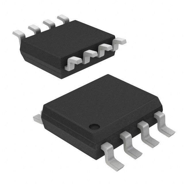
| 供应商器件封装 | 8-SOIC N |
| 其它名称 | 1016-1839-1 |
| 包装 | 剪切带 (CT) |
| 受监控电压数 | 1 |
| 复位 | 低有效 |
| 复位超时 | 最小为 140 ms |
| 安装类型 | 表面贴装 |
| 封装/外壳 | 8-SOIC(0.154",3.90mm 宽) |
| 工作温度 | 0°C ~ 70°C |
| 标准包装 | 1 |
| 电压-阈值 | 3.08V |
| 类型 | 简单复位/加电复位 |
| 输出 | - |


- 商务部:美国ITC正式对集成电路等产品启动337调查
- 曝三星4nm工艺存在良率问题 高通将骁龙8 Gen1或转产台积电
- 太阳诱电将投资9.5亿元在常州建新厂生产MLCC 预计2023年完工
- 英特尔发布欧洲新工厂建设计划 深化IDM 2.0 战略
- 台积电先进制程称霸业界 有大客户加持明年业绩稳了
- 达到5530亿美元!SIA预计今年全球半导体销售额将创下新高
- 英特尔拟将自动驾驶子公司Mobileye上市 估值或超500亿美元
- 三星加码芯片和SET,合并消费电子和移动部门,撤换高东真等 CEO
- 三星电子宣布重大人事变动 还合并消费电子和移动部门
- 海关总署:前11个月进口集成电路产品价值2.52万亿元 增长14.8%


PDF Datasheet 数据手册内容提取
SSPP770066RR//SS//TT -- SSPP770088RR//SS//TT 33..00VV//33..33VV LLooww PPoowweerr MMiiccrroopprroocceessssoorr SSuuppeerrvviissoorryy CCiirrccuuiittss April 2015 Rev. 3.0.0 GENERAL DESCRIPTION APPLICATIONS The SP706R/S/T and SP708R/S/T series is a Processors & DSPs Based Systems family of microprocessor (µP) supervisory Industrial & Medical Instruments circuits that integrate myriad components involved in discrete solutions which monitor power-supply and battery in µP and digital FEATURES systems. Precision Low Voltage Monitor The SP706R/S/T and SP708R/S/T series will SP706R/SP708R: +2.63V significantly improve system reliability and SP706S/SP708S: +2.93V operational efficiency when compared to solutions obtained with discrete components. SP706T/SP708T: +3.08V The features of the SP706R/S/T and 200ms RESET Pulse Width SP708R/S/T series include a watchdog timer, a SP706R/S/T: Active Low µP reset, a Power Fail Comparator, and a manual-reset input. SP708R/S/T: Active High and Active Low The SP706R/S/T and SP708R/S/T series is ideal Independent Watchdog Timer for 3.0V or 3.3V applications in automotive 1.6s Timeout (SP706R/S/T) systems, computers, controllers, and intelligent Enable/Disable Function instruments. The SP706R/S/T and SP708R/S/T series is an ideal solution for systems in which 40µA Maximum Supply Current critical monitoring of the power supply to the µP Debounced TTL/CMOS Manual Reset and related digital components is demanded. Input RESET Asserted Down to V =1V CC V Glitch Immunity CC Voltage Monitor for Power Failure or Low Battery Warning 8-Pin NSOIC and MSOP Packages Pin Compatible with Industry Standards 706R/S/T and 708R/S/T Part Number RESET Threshold RESET Active Manual RESET Watchdog PFI Accuracy SP706R 2.63V Low Yes Yes 4% SP706S 2.93V Low Yes Yes 4% SP706T 3.08V Low Yes Yes 4% SP708R 2.63V Low and High Yes No 4% SP708S 2.93V Low and High Yes No 4% SP708T 3.08V Low and High Yes No 4% Exar Corporation www.exar.com 48720 Kato Road, Fremont CA 94538, USA Tel. +1 510 668-7000 – Fax. +1 510 668-7001
SSPP770066RR//SS//TT -- SSPP770088RR//SS//TT 33..00VV//33..33VV LLooww PPoowweerr MMiiccrroopprroocceessssoorr SSuuppeerrvviissoorryy CCiirrccuuiittss ABSOLUTE MAXIMUM RATINGS ESD Rating (HBM - Human Body Model) .................... 2kV Continuous Power Dissipation These are stress ratings only and functional operation of SO (derate 5.88mW/°C above +70°C) ...............471mW the device at these ratings or any other above those Mini SO (derate 4.10mW/°C above +70°C) ........330mW indicated in the operation sections of the specifications below is not implied. Exposure to absolute maximum rating Storage Temperature .............................. -65°C to 160°C conditions for extended periods of time may affect Lead Temperature (Soldering, 10 sec) ....................300°C reliability. VCC .......................................................... -0.3V to 6.0V All Other Inputs (Note 1) ................... -0.3V to (VCC+0.3V) Input Current VCC ................................................................. 20mA GND ................................................................ 20mA Output Current (All outputs) ............................... 20mA ELECTRICAL SPECIFICATIONS Unless otherwise indicated, VCC = 2.7V to 5.5V (SP70xR), VCC = 3.15V to 5.5V (SP70xS), VCC = 3.0V to 5.5V (SP70xT), TA= TMIN to TMAX, typical at 25°C. Parameter Min. Typ. Max. Units Conditions Operating Voltage Range VCC 1.0 5.5 V 25 40 µA MR=VCC or floating, WDI floating, Supply Current ISUPPLY VCC = 3.3V 40 80 µA MR=VCC or floating, VCC = 5.5V 2.55 2.63 2.70 SP706R. SP708R Reset Threshold 2.85 2.93 3.00 V SP706S. SP708S 3.00 3.08 3.15 SP706T. SP708T Reset Threshold Hysteresis 20 mV Note 2 Reset Pulse Width tRS 140 200 280 ms Note 2 RESET Output Voltage VOH 0.8xVCC VRST(MAX)<VCC<3.6V, ISOURCE=500µA VOL 0.3 V VRST(MAX)<VCC<3.6V, ISINK=1.2mA VOH VCC-1.5 4.5V<VCC<5.5V, ISOURCE=800µA VOL 0.4 4.5V<VCC<5.5V, ISINK=3.2mA RESET Output Voltage VOH VCC-0.6 VRST(MAX)<VCC<3.6V, ISOURCE=215µA VOL 0.3 V VRST(MAX)<VCC<3.6V, ISOURCE=1.2mA VOH VCC-1.5 4.5V<VCC<5.5V, ISOURCE=800µA VOL 0.4 4.5V<VCC<5.5V, ISOURCE=3.2mA Watchdog Timeout Period tWD 1.00 1.60 2.25 s VCC<3.6V WDI Pulse Width tWP (note 1) 50 ns VIL=0.4V, VIH=0.8xVCC WDI Input Threshold VIL 0.6 VRST(MAX)<VCC<3.6V VIH 0.7xVCC V VRST(MAX)<VCC<3.6V VIL 0.8 VCC=5V VIH 3.5 VCC=5V WDI Input Current -1 0.02 1 µA WDI=0V or WDI=VCC WDO Output Voltage VIL 0.8xVCC V VRST(MAX)<VCC<3.6V, ISOURCE=500µA VIH 0.3 VRST(MAX)<VCC<3.6V, ISINK=1.2mA VIL VCC-1.5 4.5V<VCC<5.5V, ISOURCE=800µA © 2015 Exar Corporation 2/17 Rev. 3.0.0
SSPP770066RR//SS//TT -- SSPP770088RR//SS//TT 33..00VV//33..33VV LLooww PPoowweerr MMiiccrroopprroocceessssoorr SSuuppeerrvviissoorryy CCiirrccuuiittss Parameter Min. Typ. Max. Units Conditions VIH 0.4 4.5V<VCC<5.5V, ISINK=3.2mA 25 70 250 MR = 0V, VRST(MAX)<VCC<3.6V MR Pull-up Current µA 100 250 600 MR = 0V, 4.5V<VCC<5.5V 500 VRST(MAX)<VCC<3.6V MR Pulse Width tMR 150 ns 4.5V<VCC<5.5V MR Input Threshold VIL 0.6 VRST(MAX)<VCC<3.6V VIH 0.7xVCC V VRST(MAX)<VCC<3.6V VIL 0.8 4.5V<VCC<5.5V VIH 2.0 4.5V<VCC<5.5V 750 VRST(MAX)<VCC<3.6V MR to Reset Out Delay tMD 250 ns 4.5V<VCC<5.5V PFI Input Threshold 1.20 1.25 1.30 V VCC=3.0V - SP70xR, PFI falling VCC=3.3V - SP70xS/T, PFI falling PFI Input Current -200.00 0.01 200.00 nA VPFI = 1.36V PFO Output Voltage VIL 0.8xVCC VRST(MAX)<VCC<3.6V, ISOURCE=500µA VIH 0.3 V VRST(MAX)<VCC<3.6V, ISINK=1.2mA VIL VCC-1.5 4.5V<VCC<5.5V, ISOURCE=800µA VIH 0.4 4.5V<VCC<5.5V, ISINK=3.2mA Note 1:WDI minimum rise /fall time is 1µs. BLOCK DIAGRAM Fig. 1: SP706R/S/T Block Diagram © 2015 Exar Corporation 3/17 Rev. 3.0.0
SSPP770066RR//SS//TT -- SSPP770088RR//SS//TT 33..00VV//33..33VV LLooww PPoowweerr MMiiccrroopprroocceessssoorr SSuuppeerrvviissoorryy CCiirrccuuiittss Fig. 2: SP708R/S/T Block Diagram PIN ASSIGNMENT Fig. 3: Pin Assignment © 2015 Exar Corporation 4/17 Rev. 3.0.0
SSPP770066RR//SS//TT -- SSPP770088RR//SS//TT 33..00VV//33..33VV LLooww PPoowweerr MMiiccrroopprroocceessssoorr SSuuppeerrvviissoorryy CCiirrccuuiittss PIN DESCRIPTION Pin Number Name Description SP706R/S/T SP708R/S/T SOIC MSOP SOIC MSOP Manual Reset This input triggers a reset pulse when pulled below 0.8V. This active MR 1 3 1 3 LOW input has an internal 70µA pull-up current. It can be driven from a TTL or CMOS logic line or shorted to ground with a switch. VCC 2 4 2 4 Voltage Input GND 3 5 3 5 Ground reference for all signals Power-Fail Input PFI 4 6 4 6 When this voltage monitor input is less than 1.25V, PFO goes LOW. Connect PFI to ground or VCC when not in use. Power-Fail Output PFO 5 7 5 7 This output is LOW until PFI is less then 1.25V Watchdog Input If this input remains HIGH or LOW for 1.6s, the internal watchdog timer times out and WDO goes LOW. Floating WDI or connecting WDI WDI 6 8 - - to a high-impedance tri-state buffer disables the watchdog feature. The internal watchdog timer clears whenever RESET is asserted, WDI is tri-stated, or whenever WDI sees a rising or falling edge. N.C. - - 6 8 No Connect Active-LOW RESET Output This output pulses LOW for 200ms when triggered and stays LOW RESET 7 1 7 1 whenever VCC is below the reset threshold. It remains LOW for 200ms after Vcc rises above the reset threshold or MR goes from LOW to HIGH. A watchdog timeout will not trigger RESET unless WDO is connected to MR. Watchdog Output This output pulls LOW when the internal watchdog timer finishes its 1.6s count and does not go HIGH again until the watchdog is cleared. WDO 8 2 - - WDO also goes LOW during low-line conditions. Whenever VCC is below the reset threshold, WDO stays LOW. However, unlike RESET, WDO does not have a minimum pulse width. As soon as VCC is above the reset threshold, WDO goes HIGH with no delay. Active-HIGH RESET Output This output is the complement of RESET. Whenever RESET is HIGH, RESET - - 8 2 RESET is LOW and vice-versa. Note that the SP708R/S/T has a reset output only. ORDERING INFORMATION Temperature Packing Part Number Marking Package Note 1 Note 2 Range Quantity SP706RCN-L 0°C≤TA≤+70°C SP706RC 8-pin NSOIC Bulk Lead Free YYWWL SP706RCN-L/TR 0°C≤TA≤+70°C X 8-pin NSOIC 2.5K/Tape & Reel Lead Free SP706RCU-L 0°C≤TA≤+70°C 706R 8-pin MSOP Bulk Lead Free CXXX SP706RCU-L/TR 0°C≤TA≤+70°C YWW 8-pin MSOP 2.5K/Tape & Reel Lead Free SP706REN-L -40°C≤TA≤+85°C SP706RE 8-pin NSOIC Bulk Lead Free YYWWL SP706REN-L/TR -40°C≤TA≤+85°C X 8-pin NSOIC 2.5K/Tape & Reel Lead Free SP706REU-L -40°C≤TA≤+85°C 706R 8-pin MSOP Bulk Lead Free EXXX SP706REU-L/TR -40°C≤TA≤+85°C YWW 8-pin MSOP 2.5K/Tape & Reel Lead Free SP706SCN-L 0°C≤TA≤+70°C SP706SC 8-pin NSOIC Bulk Lead Free YYWWL SP706SCN-L/TR 0°C≤TA≤+70°C X 8-pin NSOIC 2.5K/Tape & Reel Lead Free SP706SCU-L 0°C≤TA≤+70°C 706S 8-pin MSOP Bulk Lead Free CXXX SP706SCU-L/TR 0°C≤TA≤+70°C YWW 8-pin MSOP 2.5K/Tape & Reel Lead Free © 2015 Exar Corporation 5/17 Rev. 3.0.0
SSPP770066RR//SS//TT -- SSPP770088RR//SS//TT 33..00VV//33..33VV LLooww PPoowweerr MMiiccrroopprroocceessssoorr SSuuppeerrvviissoorryy CCiirrccuuiittss Temperature Packing Part Number Marking Package Note 1 Note 2 Range Quantity SP706SEN-L -40°C≤TA≤+85°C SP706SE 8-pin NSOIC Bulk Lead Free YYWWL SP706SEN-L/TR -40°C≤TA≤+85°C X 8-pin NSOIC 2.5K/Tape & Reel Lead Free SP706SEU-L -40°C≤TA≤+85°C 706S 8-pin MSOP Bulk Lead Free EXXX SP706SEU-L/TR -40°C≤TA≤+85°C YWW 8-pin MSOP 2.5K/Tape & Reel Lead Free SP706TCN-L 0°C≤TA≤+70°C SP706TC 8-pin NSOIC Bulk Lead Free YYWWL SP706TCN-L/TR 0°C≤TA≤+70°C X 8-pin NSOIC 2.5K/Tape & Reel Lead Free SP706TCU-L 0°C≤TA≤+70°C 706T 8-pin MSOP Bulk Lead Free CXXX SP706TCU-L/TR 0°C≤TA≤+70°C YWW 8-pin MSOP 2.5K/Tape & Reel Lead Free SP706TEN-L -40°C≤TA≤+85°C SP706TE 8-pin NSOIC Bulk Lead Free YYWWL SP706TEN-L/TR -40°C≤TA≤+85°C X 8-pin NSOIC 2.5K/Tape & Reel Lead Free SP706TEU-L -40°C≤TA≤+85°C 706T 8-pin MSOP Bulk Lead Free EXXX SP706TEU-L/TR -40°C≤TA≤+85°C YWW 8-pin MSOP 2.5K/Tape & Reel Lead Free SP708REN-L -40°C≤TA≤+85°C SP708RE 8-pin NSOIC Bulk Lead Free YYWWL SP708REN-L/TR -40°C≤TA≤+85°C X 8-pin NSOIC 2.5K/Tape & Reel Lead Free SP708SCN-L 0°C≤TA≤+70°C SP708SC 8-pin NSOIC Bulk Lead Free YYWWL SP708SCN-L/TR 0°C≤TA≤+70°C X 8-pin NSOIC 2.5K/Tape & Reel Lead Free SP708SCU-L 0°C≤TA≤+70°C 708S 8-pin MSOP Bulk Lead Free UXXX SP708SCU-L/TR 0°C≤TA≤+70°C YWW 8-pin MSOP 2.5K/Tape & Reel Lead Free SP708SEN-L -40°C≤TA≤+85°C SP708SE 8-pin NSOIC Bulk Lead Free YYWWL SP708SEN-L/TR -40°C≤TA≤+85°C X 8-pin NSOIC 2.5K/Tape & Reel Lead Free SP708TCN-L 0°C≤TA≤+70°C SP708TC 8-pin NSOIC Bulk Lead Free YYWWL SP708TCN-L/TR 0°C≤TA≤+70°C X 8-pin NSOIC 2.5K/Tape & Reel Lead Free SP708TEN-L -40°C≤TA≤+85°C SP706TE 8-pin NSOIC Bulk Lead Free YYWWL SP708TEN-L/TR -40°C≤TA≤+85°C X 8-pin NSOIC 2.5K/Tape & Reel Lead Free “YY” = Year – “WW” = Work Week – “X” = Lot Number © 2015 Exar Corporation 6/17 Rev. 3.0.0
SSPP770066RR//SS//TT -- SSPP770088RR//SS//TT 33..00VV//33..33VV LLooww PPoowweerr MMiiccrroopprroocceessssoorr SSuuppeerrvviissoorryy CCiirrccuuiittss TYPICAL PERFORMANCE CHARACTERISTICS All data taken at VCC = 2.7V to 5.5V (SP70xR), VCC = 3.15V to 5.5V (SP70xS), VCC = 3.0V to 5.5V (SP70xT), TA= 25°C, unless otherwise indicated. Fig. 4: Power-Fail Comparator Fig. 5: Power-Fail Comparator De-Assertion Response Time De-Assertion Response Time Circuit Fig. 6: Power-Fail Comparator Fig. 7: Power-Fail Comparator Assertion Response Time Assertion Response Time Circuit Fig. 8: SP706 RESET Output Voltage Fig. 9: SP706 RESET Output Voltage vs. Supply Voltage vs. Supply Voltage Circuit © 2015 Exar Corporation 7/17 Rev. 3.0.0
SSPP770066RR//SS//TT -- SSPP770088RR//SS//TT 33..00VV//33..33VV LLooww PPoowweerr MMiiccrroopprroocceessssoorr SSuuppeerrvviissoorryy CCiirrccuuiittss Fig. 10: SP706 RESET Response Time Fig. 11: SP706 RESET Response Time Circuit Fig. 12: SP708 RESET and RESET Assertion Fig. 13: SP708 RESET and RESET De-Assertion Fig. 14: SP708 RESET and RESET Assertion and De-Assertion Circuit © 2015 Exar Corporation 8/17 Rev. 3.0.0
SSPP770066RR//SS//TT -- SSPP770088RR//SS//TT 33..00VV//33..33VV LLooww PPoowweerr MMiiccrroopprroocceessssoorr SSuuppeerrvviissoorryy CCiirrccuuiittss Fig. 15: SP708 RESET Output Voltage Fig. 16: SP708 RESET Response Time vs. Supply Voltage Fig. 17: SP708 RESET Output Voltage vs. Supply Voltage and RESET Response Time Circuit © 2015 Exar Corporation 9/17 Rev. 3.0.0
SSPP770066RR//SS//TT -- SSPP770088RR//SS//TT 33..00VV//33..33VV LLooww PPoowweerr MMiiccrroopprroocceessssoorr SSuuppeerrvviissoorryy CCiirrccuuiittss © 2015 Exar Corporation 10/17 Rev. 3.0.0
SSPP770066RR//SS//TT -- SSPP770088RR//SS//TT 33..00VV//33..33VV LLooww PPoowweerr MMiiccrroopprroocceessssoorr SSuuppeerrvviissoorryy CCiirrccuuiittss FEATURES previously initiated reset pulse, the pulse continues for at least another 140ms. On power The SP706R/S/T and SP708R/S/T series down, once V falls below the reset threshold, CC provides four key functions: RESET stays LOW and is guaranteed to be 0.4V 1. A reset output during power-up, power-down or less until VCC drops below 1V. and brownout conditions. The active-HIGH RESET output is simply the 2. An independent watchdog output that goes complement of the RESET output and is LOW if the watchdog input has not been toggled guaranteed to be valid with VCC down to 1.1V. within 1.6 seconds. Some µPs, such as Intel's 80C51, require an active-HIGH reset pulse. 3. A 1.25V threshold detector for power-fail warning, low battery detection, or monitoring a WATCHDOG TIMER power supply other than +3.3V/+3.0V. The SP706R/S/T-SP708R/S/T watchdog circuit 4. An active-LOW manual-reset that allows monitors the µP's activity. If the µP does not RESET to be triggered by a pushbutton switch. toggle the watchdog input (WDI) within 1.6 The SP706R/S/T devices are the same as the seconds and WDI is not tri-stated, WDO goes SP708R/S/T devices except for the active-HIGH LOW. As long as RESET is asserted or the WDI RESET substitution of the watchdog timer. input is tri-stated, the watchdog timer will stay cleared and will not count. As soon as RESET is released and WDI is driven HIGH or LOW, the THEORY OF OPERATION timer will start counting. Pulses as short as The SP706R/S/T-SP708R/S/T series is a 50ns can be detected. microprocessor (µP) supervisory circuit that Typically, WDO will be connected to the non- monitors the power supplied to digital circuits maskable interrupt input (NMI) of a µP. When such as microprocessors, microcontrollers, or V drops below the reset threshold, WDO will CC memory. The series is an ideal solution for go LOW whether or not the watchdog timer had portable, battery-powered equipment that timed out. Normally this would trigger an NMI requires power supply monitoring. but RESET goes LOW simultaneously and thus Implementing this series will reduce the overrides the NMI. number of components and overall complexity. The watchdog functions of this product family If WDI is left unconnected, WDO can be used as will continuously oversee the operational status a low-line output. Since floating WDI disables of a system. The operational features and the internal timer, WDO goes LOW only when benefits of the SP706R/S/T-SP708R/S/T series VCC falls below the reset threshold, thus are described in more detail below. functioning as a low-line output. RESET OUTPUT A microprocessor's reset input starts the µP in a known state. The SP706R/S/T-SP708R/S/T series asserts reset during power-up and prevents code execution errors during power down or brownout conditions. On power-up, once V reaches 1V, RESET is a CC guaranteed logic LOW of 0.4V or less. As V CC rises, RESET stays LOW. When V rises above CC the reset threshold, an internal timer releases RESET after 200ms. RESET pulses LOW whenever V dips below the reset threshold, CC Fig. 18: Watchdog Timing Waveforms such as in a brownout condition. When a brownout condition occurs in the middle of a © 2015 Exar Corporation 11/17 Rev. 3.0.0
SSPP770066RR//SS//TT -- SSPP770088RR//SS//TT 33..00VV//33..33VV LLooww PPoowweerr MMiiccrroopprroocceessssoorr SSuuppeerrvviissoorryy CCiirrccuuiittss MANUAL RESET The manual-reset input (MR) allows RESET to be triggered by a pushbutton switch. The switch is effectively debounced by the 140ms minimum RESET pulse width. MR is TTL/CMOS logic compatible, so it can be driven by an external logic line. MR can be used to force a watchdog timeout to generate a RESET pulse in the SP706R/S/T-SP708R/S/T. Simply connect WDO to MR. Ensuring a Valid Reset Output Down to V =0V CC When V falls below 1V, the RESET output no CC longer sinks current, it becomes an open circuit. Fig. 19: Timing Diagrams with WDI tri-stated. High-impedance CMOS logic inputs can drift to undetermined voltages if left undriven. If a pull- POWER-FAIL COMPARATOR down resistor is added to the RESET pin, any The power-fail comparator can be used for stray charge or leakage currents will be shunted various purposes because its output and non to ground, holding RESET LOW. The resistor inverting input are not internally connected. value is not critical. It should be about 100KΩ, The inverting input is internally connected to a large enough not to load RESET and small 1.25V reference. enough to pull RESET to ground. To build an early-warning circuit for power MONITORING VOLTAGES OTHER THAN THE failure, connect the PFI pin to a voltage divider as shown in Figure 20. Choose the voltage UNREGULATED DC INPUT divider ratio so that the voltage at PFI falls Monitor voltages other than the unregulated DC below 1.25V just before the +5V regulator by connecting a voltage divider to PFI and drops out. Use PFO to interrupt the µP so it can adjusting the ratio appropriately. If required, prepare for an orderly power-down. add hysteresis by connecting a resistor (with a value approximately 10 times the sum of the two resistors in the potential divider network) between PFI and PFO. A capacitor between PFI and GND will reduce the power-fail circuit's sensitivity to high-frequency noise on the line being monitored. RESET can be used to monitor voltages other than the +3.3V/+3.0V V line. CC Connect PFO to MR to initiate a RESET pulse when PFI drops below 1.25V. Figure 21 shows the SP706R/S/T-SP708R/S/T series configured to assert RESET when the +3.3V/3.0V supply falls below the RESET threshold, or when the +12V supply falls below approximately 11V. MONITORING A NEGATIVE VOLTAGE SUPPLY The power-fail comparator can also monitor a negative supply rail, shown in Figure 22. When Fig. 20: Typical Operating Circuit the negative rail is good (a negative voltage of large magnitude), PFO is LOW. By adding the resistors and transistor as shown, a HIGH PFO © 2015 Exar Corporation 12/17 Rev. 3.0.0
SSPP770066RR//SS//TT -- SSPP770088RR//SS//TT 33..00VV//33..33VV LLooww PPoowweerr MMiiccrroopprroocceessssoorr SSuuppeerrvviissoorryy CCiirrccuuiittss triggers RESET. As long as PFO remains HIGH, INTERFACING TO µPS WITH BIDIRECTIONAL the SP706R/S/T-SP708R/S/T series will keep RESET PINS RESET asserted (where RESET = LOW and µPs with bidirectional RESET pins, such as the RESET = HIGH). Note that this circuit's Motorola 68HC11 series, can contend with the accuracy depends on the PFI threshold SP706/708 RESET output. If, for example, the tolerance, the V line, and the resistors. CC RESET output is driven HIGH and the µP wants to pull it LOW, indeterminate logic levels may result. To correct this, connect a 4.7KΩ resistor between the RESET output and the µP reset I/O, as shown if Figure 23. Buffer the RESET output to other system components. Fig. 21: Monitoring +3.3V/+3.0V and +12V Power Supplies Fig. 23: Interfacing to Microprocessors with Bidirectional RESET I/O (SP706) NEGATIVE-GOING VCC TRANSIENT While issuing resets to the μP during power-up, power-down, and brownout conditions, these supervisors are relatively immune to short duration negative-going VCC transients (glitches). It is usually undesirable to reset the μP when V experiences only small glitches. CC Figure 24 shows maximum transient duration vs. reset-comparator overdrive, for which reset pulses are not generated. The data was generated using negative-going V pulses, CC starting at 3.3V and ending below the reset threshold by the magnitude indicated (reset comparator overdrive). The graph shows the maximum pulse width a negative-going V CC transient may typically have without causing a reset pulse to be issued. As the amplitude of the transient increases (i.e. goes farther below Fig. 22: Monitoring a Negative Voltage Supply the reset threshold), the maximum allowable © 2015 Exar Corporation 13/17 Rev. 3.0.0
SSPP770066RR//SS//TT -- SSPP770088RR//SS//TT 33..00VV//33..33VV LLooww PPoowweerr MMiiccrroopprroocceessssoorr SSuuppeerrvviissoorryy CCiirrccuuiittss pulse width decreases. Typically, a V transient CC that goes 100mV below the reset threshold and lasts for 40μs or less will not cause a reset pulse to be issued. A 100nF bypass capacitor mounted close to the VCC pin provides additional transient immunity. Fig. 25: Supply Current vs. Temperature Fig. 24: Maximum Transient Duration without Causing a Reset Pulse vs. Reset Comparator Overdrive APPLICATIONS The SP706P/R/S/T-SP708R/S/T series offers unmatched performance and the lowest power consumption for these industry standard devices. Refer to Figures 25 and 26 for supply current performance characteristics rated against temperature and supply voltages. Fig. 26: Supply Current vs. Supply Voltage © 2015 Exar Corporation 14/17 Rev. 3.0.0
SSPP770066RR//SS//TT -- SSPP770088RR//SS//TT 33..00VV//33..33VV LLooww PPoowweerr MMiiccrroopprroocceessssoorr SSuuppeerrvviissoorryy CCiirrccuuiittss PACKAGE SPECIFICATION 8-PIN NSOIC © 2015 Exar Corporation 15/17 Rev. 3.0.0
SSPP770066RR//SS//TT -- SSPP770088RR//SS//TT 33..00VV//33..33VV LLooww PPoowweerr MMiiccrroopprroocceessssoorr SSuuppeerrvviissoorryy CCiirrccuuiittss 8-PIN MSOP © 2015 Exar Corporation 16/17 Rev. 3.0.0
SSPP770066RR//SS//TT -- SSPP770088RR//SS//TT 33..00VV//33..33VV LLooww PPoowweerr MMiiccrroopprroocceessssoorr SSuuppeerrvviissoorryy CCiirrccuuiittss REVISION HISTORY Revision Date Description 2.0.0 06/04/2010 Reformat of datasheet 3.0.0 04/14/2015 Change of specs to match industry standards [ECN 1517-08] FOR FURTHER ASSISTANCE Email: customersupport@exar.com Exar Technical Documentation: http://www.exar.com/TechDoc/default.aspx? EXAR CORPORATION HEADQUARTERS AND SALES OFFICES 48720 Kato Road Fremont, CA 94538 – USA Tel.: +1 (510) 668-7000 Fax: +1 (510) 668-7030 www.exar.com NOTICE EXAR Corporation reserves the right to make changes to the products contained in this publication in order to improve design, performance or reliability. EXAR Corporation assumes no responsibility for the use of any circuits described herein, conveys no license under any patent or other right, and makes no representation that the circuits are free of patent infringement. Charts and schedules contained herein are only for illustration purposes and may vary depending upon a user’s specific application. While the information in this publication has been carefully checked; no responsibility, however, is assumed for inaccuracies. EXAR Corporation does not recommend the use of any of its products in life support applications where the failure or malfunction of the product can reasonably be expected to cause failure of the life support system or to significantly affect its safety or effectiveness. Products are not authorized for use in such applications unless EXAR Corporation receives, in writing, assurances to its satisfaction that: (a) the risk of injury or damage has been minimized; (b) the user assumes all such risks; (c) potential liability of EXAR Corporation is adequately protected under the circumstances. Reproduction, in part or whole, without the prior written consent of EXAR Corporation is prohibited. © 2015 Exar Corporation 17/17 Rev. 3.0.0
Mouser Electronics Authorized Distributor Click to View Pricing, Inventory, Delivery & Lifecycle Information: E xar: SP706SCU-L/TR SP706SEU-L/TR SP708TCN-L/TR SP708REN-L/TR SP706RCU-L/TR SP706REU-L/TR SP708TEN-L/TR SP708TCN-L SP706REN-L SP706RCN-L SP706REU-L SP708TEN-L SP708CN-L SP708CN- L/TR SP708SCU-L SP706TEN-L/TR SP706TCN-L/TR SP708SEN-L SP706SCU-L SP708SEN-L/TR SP708REN-L SP708SCN-L/TR SP708EN-L SP706TEN-L SP708EN-L/TR SP706TEU-L SP706SEN-L SP706SCN-L SP706SEN-L/TR SP706SCN-L/TR SP708SCN-L SP706SEU-L SP708SCU-L/TR SP706TCN-L SP706TCU-L SP706RCU-L SP706TEU-L/TR SP706TCU-L/TR SP706REN-L/TR SP706RCN-L/TR