ICGOO在线商城 > 光电元件 > LED 指示 - 分立 > SMLA13WBDW1
 Datasheet下载
- 型号: SMLA13WBDW1
- 制造商: ROHM Semiconductor
- 库位|库存: xxxx|xxxx
- 要求:
| 数量阶梯 | 香港交货 | 国内含税 |
| +xxxx | $xxxx | ¥xxxx |
查看当月历史价格
查看今年历史价格
SMLA13WBDW1产品简介:
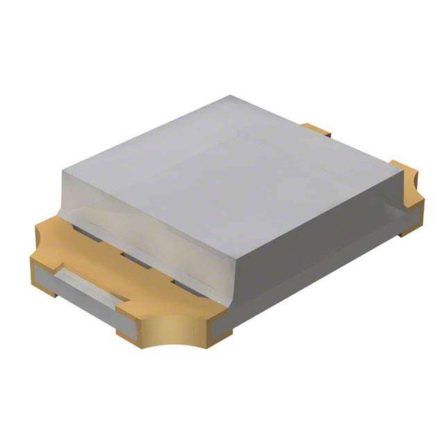
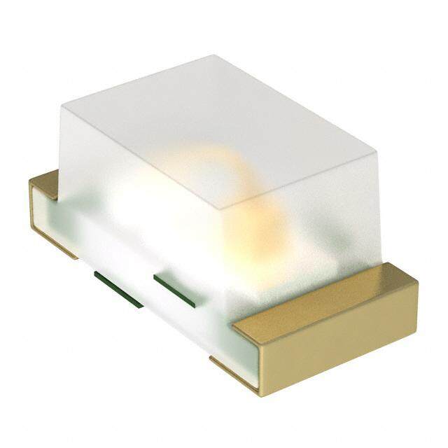
ICGOO电子元器件商城为您提供SMLA13WBDW1由ROHM Semiconductor设计生产,在icgoo商城现货销售,并且可以通过原厂、代理商等渠道进行代购。 SMLA13WBDW1价格参考。ROHM SemiconductorSMLA13WBDW1封装/规格:LED 指示 - 分立, 白色 LED 指示 - 分立 3.1V 2-SMD,无引线。您可以下载SMLA13WBDW1参考资料、Datasheet数据手册功能说明书,资料中有SMLA13WBDW1 详细功能的应用电路图电压和使用方法及教程。
Rohm Semiconductor的SMLA13WBDW1是一款白色LED,属于LED指示 - 分立类别,主要应用于需要高效、小型化和低功耗指示灯的场景。以下是其典型应用场景:

1. 消费电子设备:用于手机、平板电脑、笔记本电脑等设备的状态指示灯,例如充电指示、电源开关指示等。

2. 家用电器:在冰箱、洗衣机、空调等家电中作为操作面板的状态提示灯,提供直观的视觉反馈。

3. 工业设备:在控制面板或仪表盘上用作运行状态、报警或模式切换的指示灯,确保操作人员能够快速了解设备状态。

4. 医疗设备:用于便携式医疗设备(如血压计、血糖仪)中的指示功能,提供清晰可见的操作指引。

5. 汽车电子:适用于车内氛围灯、仪表盘指示灯或控制按钮背光,增强驾驶体验和安全性。

6. 物联网(IoT)设备:为智能家居设备、传感器节点等提供工作状态或网络连接状态的指示功能。

7. 便携式设备:如蓝牙音箱、智能手环等,用于显示电量、配对状态或其他功能信息。

SMLA13WBDW1以其高亮度、低功耗和紧凑封装的特点,非常适合对空间和能效要求较高的应用场合。此外,其稳定的性能和长寿命也使其成为各类电子产品的理想选择。
| 参数 | 数值 |
| 产品目录 | |
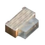
| 描述 | LED WHITE SIDE VIEW SMD标准LED-SMD White 74mW 20mA Side View |
| 产品分类 | |
| LED大小 | 0605 |
| 品牌 | ROHM Semiconductor |
| 产品手册 | |
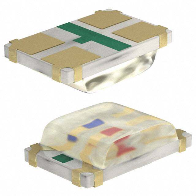
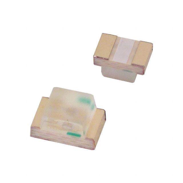
| 产品图片 |
|
| rohs | 符合RoHS无铅 / 符合限制有害物质指令(RoHS)规范要求 |
| 产品系列 | LED发射器,标准LED-SMD,ROHM Semiconductor SMLA13WBDW1EXCELED™ |
| 数据手册 | |
| 产品型号 | SMLA13WBDW1 |
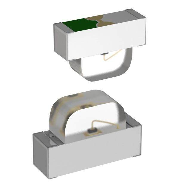
| 产品目录绘图 |
|
| 产品目录页面 | |
| 产品种类 | 标准LED-SMD |
| 光强度 | 170 mcd |
| 其它名称 | 511-1604-6 |
| 包装 | Digi-Reel® |
| 商标 | ROHM Semiconductor |
| 大小/尺寸 | 1.60mm 长 x 1.15mm 宽 |
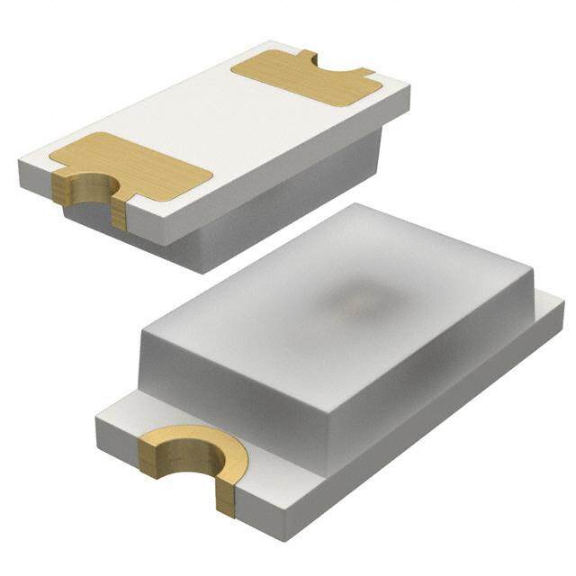
| 安装类型 | 表面贴装,直角 |
| 封装 | Reel |
| 封装/外壳 | 2-SMD,无引线 |
| 封装/箱体 | 0605 |
| 工厂包装数量 | 3000 |
| 显示角 | 150 deg |
| 最大工作温度 | + 85 C |
| 最小工作温度 | - 30 C |
| 标准包装 | 1 |
| 正向电压 | 3.1 V |
| 正向电流 | 10 mA |
| 毫烛光等级 | 180mcd |
| 波长-主 | 6900K |
| 波长-峰值 | - |
| 测试电流时的光通量 | - |
| 照明颜色 | White |
| 电压-正向(Vf)(典型值) | 3.1V |
| 电流-测试 | 10mA |
| 视角 | - |
| 透镜样式/尺寸 | 矩形,带平顶,1.2mm x 0.55mm |
| 透镜类型 | 散射,白色 |
| 透镜颜色/类型 | Milky White Diffused |
| 颜色 | 冷白色 |
| 高度 | 0.55mm |


- 商务部:美国ITC正式对集成电路等产品启动337调查
- 曝三星4nm工艺存在良率问题 高通将骁龙8 Gen1或转产台积电
- 太阳诱电将投资9.5亿元在常州建新厂生产MLCC 预计2023年完工
- 英特尔发布欧洲新工厂建设计划 深化IDM 2.0 战略
- 台积电先进制程称霸业界 有大客户加持明年业绩稳了
- 达到5530亿美元!SIA预计今年全球半导体销售额将创下新高
- 英特尔拟将自动驾驶子公司Mobileye上市 估值或超500亿美元
- 三星加码芯片和SET,合并消费电子和移动部门,撤换高东真等 CEO
- 三星电子宣布重大人事变动 还合并消费电子和移动部门
- 海关总署:前11个月进口集成电路产品价值2.52万亿元 增长14.8%

PDF Datasheet 数据手册内容提取
SML-A1x Series EXCELEDTM Data Sheet ■Features ■Outline • EXCELEDTM series • Compact size side-view LEDs ■Size Color V U D W Y 1611(0605) Type 1.6×1.15mm(t=0.55mm) M P E B WB ■Dimensions ■Recommended Solder Pattern Tolerance : ±0.1 (unit : mm) ■Specifications Absolute Maximum Ratings (Ta=25ºC) Electrical and Optical Characteristics (Ta=25ºC) Part No. Chip StructureEmitting Power ForwardPeak ForwardReverseOperating Temp.Storage Temp. Forward Voltage VF Reverse Current IR D/oCmhroinmaantitc Wity acovoerldeinnagtteh(x λ,y)D Luminous Intensity IV Color DissipationCurrent Current Voltage Typ. IF Max. VR Min.*2 Typ. Max.*2 IF Min. Typ. IF PD(mW) IF(mA) IFP(mA) VR(V) Topr(ºC) Tstg(ºC) (V) (mA) (μA) (V) (nm) (nm) (nm) (mA) (mcd) (mcd) (mA) SML-A12V8T 624 630 636 16 40 54 20 2.2 SML-A12U8T Red 614 620 626 25 63 SML-A12UT(J) 75 30 2.0 - 624 - 36 SML-A12D8T 54 20 2.2 601 605 609 40 100 Orange -40~+85 -40~+100 10 SML-A12DT(J) - 606 - AlGaInP 75 30 2.0 20 20 36 20 SML-A12WT(J) 587 593 Yellow 100*1 590 63 SML-A12Y8T 5 5 586 594 25 54 20 2.2 SML-A12M8T 568 572 576 10 25 Yellowish green SML-A12MT(J) 65 25 -30~+85 -40~+85 2.1 100 567 570 573 14 40 SML-A12P8T 54 2.2 10 556 560 564 2.5 6.3 Green SMLA12EC6T 68 20 3.0 100 520 527 535 56 -40~+85 -40~+100 SMLA13BC8T InGaN Blue 66 5 465 470 475 5 22 36 5 2.9 10 SMLA12WBC7W *3 White 33 10 50 (x,y)(0.30,0.30) 56 *1 : 1/10,1kHz *2 : Measurement tolerance:±1nm、*3:Brightness for white color is noted with chromaticity coordinate(x,y). EXCELEDTM is ROHM's pending trademark. ________________________________________________________ www.rohm.com ©2018 ROHM Co., Ltd. All rights reserved 1/11 2020.01 - Rev.013
[SML-A1x series] [Data Sheet] ■Electrical Characteristics Curves Reference Fig.1 Forward Current Fig.2 Luminous Intensity - - Forward Voltages Atmosphere Temperature 100 ] 1.6 . SML-A12V8T Ta=25ºC .u I =20mA SML-A12U8T a F [ A] SML-A12D8T Y 1.4 m SML-A12Y8T T SML-A12M8T I [ SML-A12P8T S F N I E 1.2 : T T N N I RE 10 US 1 R O U N C I D M 0.8 SML-A12V8T R U SML-A12U8T A L SML-A12D8T W E SML-A12Y8T R V 0.6 SML-A12M8T I O T SML-A12P8T F A L 1 E 0.4 R 1 1.2 1.4 1.6 1.8 2 2.2 2.4 2.6 2.8 3 -40 -30 -20 -10 0 10 20 30 40 50 60 70 80 90 100 FORWARD VOLTAGE : V [V] ATMOSPHERE TEMPERATURE : Ta [ºC] F Fig.3 Luminous Intensity - Forward Current Fig.4 Derating 1.5 ] 30 A 1.4 SML-A12V8T Ta=25ºC m SITY 11..23 SSSMMMLLL---AAA111222UDY888TTT : [ 25 N T E 1.1 SML-A12M8T N T SML-A12P8T E N 1 R 20 I R S 0.9 U U 0.8 C O D 15 N 0.7 R MI 0.6 A W LU 0.5 R 10 SML-A12V8T VE 0.4 FO SSMMLL--AA1122UD88TT I 0.3 M SML-A12Y8T T 5 SML-A12M8T LA 0.2 MU SML-A12P8T E 0.1 I R X 0 A 0 0 2 4 6 8 10 12 14 16 18 20 M -40 -30 -20 -10 0 10 20 30 40 50 60 70 80 90 100 FORWARD CURRENT : I [mA] AMBIENT TEMPERATURE : Ta [ºC] F ________________________________________________________ www.rohm.com ©2018 ROHM Co., Ltd. All rights reserved 2/11 2020.01 - Rev.013
[SML-A1x series] [Data Sheet] ■Electrical Characteristics Curves Reference Fig.1 Forward Current Fig.2 Luminous Intensity - - Forward Voltages Atmosphere Temperature 100 ] 1.8 . Ta=25ºC u I =20mA a. F A] [ 1.6 m Y T [F SI 1.4 I N : E T T 1.2 N N E I RR 10 US 1 U O C N D MI 0.8 R U A L W SML-A12UT(J) E 0.6 SML-A12UT(J) R SML-A12DT(J) V SML-A12DT(J) O SML-A12WT(J) I SML-A12WT(J) F SML-A12MT(J) AT 0.4 SML-A12MT(J) L 1 E R 0.2 1 1.2 1.4 1.6 1.8 2 2.2 2.4 2.6 2.8 3 -40 -30 -20 -10 0 10 20 30 40 50 60 70 80 90 100 FORWARD VOLTAGE : V [V] ATMOSPHERE TEMPERATURE : Ta [ºC] F Fig.3 Luminous Intensity - Forward Current Fig.4 Derating Y A] 40 T 1.4 SML-A12UT(J) m I NS SSMMLL--AA1122DWTT((JJ)) [ 35 TE 1.2 SML-A12MT(J) T : N N 30 I E S 1 R U R O U 25 N C MI 0.8 D 20 R U A L 0.6 W E 15 V R I O T 0.4 F A 10 L M SML-A12UT(J) E U R 0.2 M 5 SSMMLL--AA1122DWTT((JJ)) Ta=25ºC XI SML-A12MT(J) A 0 M 0 0 2 4 6 8 10 12 14 16 18 20 22 24 26 28 30 -40 -30 -20 -10 0 10 20 30 40 50 60 70 80 90 100 FORWARD CURRENT : I [mA] AMBIENT TEMPERATURE : Ta [ºC] F ________________________________________________________ www.rohm.com ©2018 ROHM Co., Ltd. All rights reserved 3/11 2020.01 - Rev.013
[SML-A1x series] [Data Sheet] ■Electrical Characteristics Curves Reference Fig.1 Forward Current Fig.2 Luminous Intensity - - Forward Voltages Atmosphere Temperature ] 100 u. 1.6 . a mA] SSMMLLAA1123EBCC68TT Ta=25ºC Y [ SSMMLLAA1123EBCC68TT IF=5mA [ SMLA12WBC7W IT 1.4 SMLA12WBC7W F S I N : E T T 1.2 N N E I R S R U U 10 O 1 C N I D M AR LU 0.8 W E R V O I F T 0.6 A L E R 1 0.4 2 2.2 2.4 2.6 2.8 3 3.2 3.4 3.6 3.8 4 -40 -30 -20 -10 0 10 20 30 40 50 60 70 80 90 100 FORWARD VOLTAGE : V [V] ATMOSPHERE TEMPERATURE : Ta [ºC] F Fig.3 Luminous Intensity - Forward Current Fig.4 Derating ] A 3 m 25 Y 2.8 SMLA12EC6T Ta=25ºC [ 24 TENSIT 222...246 SSMMLLAA1132BWCB8CT7W RENT : 1222290123 N 18 R I 2 U 17 S C 16 U 1.8 15 O D 14 N 1.6 R 13 MI 1.4 WA 12 11 E LU 1.21 FOR 1890 V I 0.8 M 7 T U 6 LA 0.6 M 5 SMLA12EC6T E 0.4 XI 4 SMLA13BC8T R A 3 SMLA12WBC7W 0.2 M 2 1 0 0 0 2 4 6 8 10 12 14 16 18 20 -40 -30 -20 -10 0 10 20 30 40 50 60 70 80 90 100 FORWARD CURRENT : I [mA] AMBIENT TEMPERATURE : Ta [ºC] F ________________________________________________________ www.rohm.com ©2018 ROHM Co., Ltd. All rights reserved 4/11 2020.01 - Rev.013
[SML-A1x series] [Data Sheet] ■Viewing Angle Reference SCANNING ANGLE (deg) SCANNING ANGLE (deg) X - Y SML-A12x(J) Series X’ - Y’ SMLA12EC6T 20° 10° 0° 10° 20° SML-A12x8 Series 20° 10° 0° 10° 20° SMLA13BC8T 30° 30° SMLA12EC6T 30° 30° SML-A12x8 Series 40° 40° 40° 40° SML-A12x(J) Series 50° 50° 50° 50° 60° 60° 60° 60° 70° 70° 70° 70° 80° 80° 80° 80° 90° 90° 90° 90° 100 50 0 50 100 100 50 0 50 100 RELATIVE INTENSITY (%) RELATIVE INTENSITY (%) SCANNING ANGLE (deg) SCANNING ANGLE (deg) X -Y 20 10 0 10 20 X' -Y' 20 10 0 10 20 30 30 30 30 SMLA13BC8T series 40 40 スキャン方向 40 40 (Scannスiキnャgン 方Di向rection) 50 50 (Scanning Direction) 50 50 60 60 60 60 70 70 70 70 80 80 80 80 90 90 90 90 100 50 0 50 100 100 50 0 50 100 X Y X' Y' RELATIVE INTENSITY (%) RELATIVE INTENSITY (%) ________________________________________________________ www.rohm.com ©2018 ROHM Co., Ltd. All rights reserved 5/11 2020.01 - Rev.013
[SML-A1x series] [Data Sheet] ■Rank Reference of Brightness* *Measurement tolerance:±10% Red(V,U) (Ta=25ºC, IF=20mA) Rank G H J K L M N P Q R S T U V W X Iv (mcd) 1.0〜1.6 1.6〜2.5 2.5〜4.0 4.0〜6.3 6.3〜10 10〜16 16〜25 25〜40 40〜63 63〜100 100〜160 160〜250 250〜400 400〜630630〜10001000〜1600 SML-A12V8T SML-A12U8T SML-A12UT(J) Orange(D) (Ta=25ºC, IF=20mA) Rank G H J K L M N P Q R S T U V W X Iv (mcd) 1.0〜1.6 1.6〜2.5 2.5〜4.0 4.0〜6.3 6.3〜10 10〜16 16〜25 25〜40 40〜63 63〜100 100〜160 160〜250 250〜400 400〜630630〜10001000〜1600 SML-A12D8T SML-A12DT(J) Yellow(Y, W) (Ta=25ºC, IF=20mA) Rank G H J K L M N P Q R S T U V W X Iv (mcd) 1.0〜1.6 1.6〜2.5 2.5〜4.0 4.0〜6.3 6.3〜10 10〜16 16〜25 25〜40 40〜63 63〜100 100〜160 160〜250 250〜400 400〜630630〜10001000〜1600 SML-A12Y8T SML-A12WT(J) Yellowish Green/Green(M,P) (Ta=25ºC, IF=20mA) Rank G H J K L M N P Q R S T U V W X Iv (mcd) 1.0〜1.6 1.6〜2.5 2.5〜4.0 4.0〜6.3 6.3〜10 10〜16 16〜25 25〜40 40〜63 63〜100 100〜160 160〜250 250〜400 400〜630630〜10001000〜1600 SML-A12MT(J) SML-A12M8T SML-A12P8T Green(E) (Ta=25ºC, IF=5mA) Rank G H J K L M N P Q R S T U V W Iv (mcd) 0.9〜1.4 1.4〜2.2 2.2〜3.6 3.6〜5.6 5.6〜9 9〜14 14〜22 22〜36 36〜56 56〜90 90〜140 140〜220 220〜360 360〜560 560〜900 SMLA12EC6T Blue(B) (Ta=25ºC, IF=5mA) Rank G H J K L M N P Q R S T U V W Iv (mcd) 0.9〜1.4 1.4〜2.2 2.2〜3.6 3.6〜5.6 5.6〜9 9〜14 14〜22 22〜36 36〜56 56〜90 90〜140 140〜220 220〜360 360〜560 560〜900 SMLA13BC8T White(WB) (Ta=25ºC, IF=5mA) Rank G H J K L M N P Q R S T U V W Iv (mcd) 0.9〜1.4 1.4〜2.2 2.2〜3.6 3.6〜5.6 5.6〜9 9〜14 14〜22 22〜36 36〜56 56〜90 90〜140 140〜220 220〜360 360〜560 560〜900 SMLA12WBC7W ■Chromaticity Diagram 0.4 C K y F E CI 0.3 H (Ta=25℃、If=5mA) A A F H K C x y x y x y x y x y 0.280 0.248 0.283 0.305 0.287 0.295 0.304 0.330 0.330 0.318 0.296 0.276 0.304 0.330 0.307 0.315 0.330 0.360 0.356 0.351 0.283 0.305 0.307 0.315 0.311 0.294 0.330 0.318 0.361 0.385 0.2 0.264 0.267 0.287 0.295 0.296 0.276 0.311 0.294 0.330 0.360 0.2 0.3 0.4 Measurement tolerance:±0.02 CIE x ________________________________________________________ www.rohm.com ©2018 ROHM Co., Ltd. All rights reserved 6/11 2020.01 - Rev.013
[SML-A1x series] [Data Sheet] ■Taping(T86) 2±40.0±50.1 φ1.5+00.1 ±0.11.75 ±0.11.85 5.5 ±0.053.5 8.0 1.4±0.1 ~0.5 0.7+-00..107 0 11.4±1 φ13 +1φ600 0φ180-3 Unit:mm Packingquantity Note)Tolerance is within ±0.2mm unless 3,000pcs/reel otherwise specified. Pull direction ■Part No. Construction *"-"will be taken out for emitting color Special Code will be applied for Chromaticity rank Rank sign WB/B/E series. Emitting color WB/B/E series. (for white LED) (Brightness Rank)* S M L - A 1 2 U 8 T T 8 6 P Series name Package Type Chip type Emitting Color Resin Color Taping Specification SMLChip LED P1 1.0x0.6 t=0.2mm 0 Standard Type V Red T Transparent Colorless T86 Cathode at sprocket hole side(the top) E1 1.6x0.8 t=0.36mm 1 Low Current Type U Red W Milkey White T87 Anode at sprocket hole side(the top) D11.6x0.8 t=0.55mm 2 High Brightness type U2 Red B Black 1 For white LED, H1 3 D Orange 3 csthode at sprocket hole side 2.0x1.25 t=0.8mm M1 4 Y3 Yellow 01 3.0x2.0 t=1.3mm 5 Y2 Yellow notice)S1 series、81 seires Ultra High Brightness type Z1/ZN 3.5x2.8 t=1.9mm 6 Y Yellow T86 Cathode at sprocket hole side(the back) A1 1.6x1.15 t=0.55mm 7 W Yellow T68 Cathode at sprocket hole side(the top) 81/82 3.4x1.25 t=1.1mm 8 M2 Yellowish green K1 4.5x2.0 t=0.6mm M Yellowish green *Concerning the Brightness rank. S1 3.2x1.6 t=1.85mm F Green *Please refer to the rank chart above for P2 1.0x1.0 t=0.2mm P Green luminous intensity classification. 52 1.3x1.5 t=0.6mm E Green *Part name is individual for each rank. P34 1.0x1.0 t=0.2mm B Blue *When shipped as sample,the part name will P36 1.5x1.0 t=0.2mm WB White be a representative part name. VN3.5x2.8 t=0.6mm T Phototransistors General products are free of ranks. RGB Red/Green/Blue Please contact sales if rank appointment SCMChip LED 01 3.0x1.5 t=2.2mm is needed. ■Packing Specification ROHM LED products are being shipped with desiccant (silica gel) included in moisture-proof bags. Pasting the moisture sensitive label on the outer surface of the moisture-proof bags or enclosing the humidity indication card inside the bag is available upon request. _Pl_ea_se_ c_on_ta_ct_ t_he_ n_ea_re_st_ s_ale_s _of_fic_e _or_ d_ist_rib_u_te_r i_f n_ec_e_ss_ar_y.________________________ www.rohm.com ©2018 ROHM Co., Ltd. All rights reserved 7/11 2020.01 - Rev.013
[SML-A1x series] [Data Sheet] ■Precaution (Surface Mount Device) 1.Storage If the product is heated during the reflow under the condition of hygroscopic state, it may vaporize and expand which will influence the performance of the product. Therefore, the package is waterproof. Please use the product following the conditions: ・Using Conditions Classification Temperature Humidity Expiration Date Remark Within 1 year ①Before using 5〜30℃ 30〜70%RH Storage with waterproof package from Receiving ②After opening Please storing in the airtight container 5〜30℃ Below 70%RH Within 168h package with our desiccant (silica gel) ・Baking Bake the product in case of below: ①The expiration date is passed. ②The color of indicator (silica gel) turned from blue to colorless or from green to pink. (Even if the product is within the expiration date.) ・Baking Conditions Temperature Time Humidity 60±3℃ 12〜24h Below 20%RH ・Bake products in reel. ・Reel and embossed tape are easy to be deformed when baking, Remark so please try not to apply stress on it. ・Recommend bake once. 2.Application Methods 2-1.Precaution for Drive System and Off Mode Design the circuit without the electric load exceeding the ABSOLUTE MAXIMUM RATING that applies on the products. If drive by constant voltage, it may cause current deviation of the LED and result in deviation of luminous intensity, so we recommend to drive by constant current. (Deviation of VF Value will cause deviation of current in LED.) Furthermore, for off mode, please do not apply voltage neither forward nor reverse. Especially, for the products with the Ag-paste used in the die bonding, thereʼs high possibility to cause electro migration and result in function failure. 2-2.About Derating It is considered that derating characteristics will not result in LED chip's electrical destruction. Even within the derating, the reliability and luminous life can be affected depending on operating conditions and ambient environment. So we would be appreciate it if you can confirm with your application again. 2-3.About product life Depending on operating conditions and environment(applied current, ambient temperature and humidity, corrosive gas), decreasing of luminosity and change of chromaticity may occur even within the specification conditions. Please contact our sales office if you use it for the following applications. ①It requires long luminosity life ②It is always lit 2-4.Applied Stress on Product No resin hardening agent such as filler is used in the sealing resin of the product. Therefore, please pay attention to the overstress on it which may influence its reliability. 2-5.Usage The Product is LED. We are not responsible for the usage as the diode such as Protection Chip, Rectifier, Switching and so on. ________________________________________________________ www.rohm.com ©2018 ROHM Co., Ltd. All rights reserved 8/11 2020.01 - Rev.013
[SML-A1x series] [Data Sheet] 3.Others 3-1.Surrounding Gas Notice that if it is stored under the condition of acid gas (chlorine gas, sulfured gas) or alkali gas (ammonia), it may result in low soldering ability (caused by the change in quality of the plating surface ) or optical characteristics changes (light intensity, chrominance) and change in quality of cause die bonding (Ag-paste) materials. All of the above will function failure of the products. Therefore, please pay attention to the storage environment for mounted product (concern the generated gas of the surrounding parts of the products and the atmospheric environment). 3-2.Electrostatic Damage The product is part of semiconductor and electrostatic sensitive, thereʼs high possibility to be damaged by the electrostatic discharge. Please take appropriate measures to avoid the static electricity from human body and earthing of production equipment. Especially, InGaN type LEDs have lower resistance value of electrostatic discharge and it is recommended to introduce the ESD protection circuit. The resistance values of electrostatic discharge (actual values) vary with products, therefore, please call our Sales staffs for inquiries. 3-3. Electromagnetic Wave Applications with strong electromagnetic wave such as, IH cooker, will influence the reliability of LED, therefore please evaluate before using it. ________________________________________________________ www.rohm.com ©2018 ROHM Co., Ltd. All rights reserved 9/11 2020.01 - Rev.013
[SML-A1x series] [Data Sheet] 4.Mounting 4-1. Soldering ・No resin hardening agent such as filler is used in the sealing resin of the product. Therefore, resin expansion and moisture absorption at humidity will cause heat stress during soldering process and finally has bad influence on the productʼs reliability. ・The product is not guaranteed for flow soldering. ・Do not expose the product in the environment of high temperature (over 100℃) or rapid temperature shift (within 3℃/sec. of temperature gradient) during the flow soldering of surrounding parts. In case of carrying out flow soldering of surrounding parts without recommended conditions, please contact us for inquiries. ・Please set appropriate reflow temperature based on our product usage conditions and specification. ・The max for reflowing is 2 times, please finish the second reflow soldering and flow soldering with other parts within the usage limitation after open the moistureproof package. ・Compare with N2 reflow, during air reflow, because of the heat and surrounding conditions, it may cause the discoloration of the resin. ・For our product that has no solder resist, because of its solder amount and soldering conditions, one of its specific characteristics is that solder will penetrate into LED. Thus, there's high possibility that will influence its reliability.Therefore, please be informed, concerning it before using it. 4-2. Automatic Mounting 4-2-1. Silicon Resin Sealing Product The sealing resin of LED is very soft, so please select adsorption nozzle that would not apply stress directly on the sealing section. 4-2-2. Mini Package (Smaller than 1608 size) ・Vibration may result in low mounting rate since it will cause the static electricity of product and adhere to top cover tape. Therefore, the magnet should be set on parts feeder cassette of the mounter to control the product stabilization. In addition, it is recommended to set ionizer to prevent electrostatic charge. 4-3. Mounting Location The stress like bending stress of circuit board dividing after mounting, may cause LED package crack or damage of LED internal junction, therefore, please concern the mounting direction and position to avoid bending or screwing with great stress of the circuit board. Stress strength according to he mounting position: A>B>C>D 4―4. Mechanical Stress after Mounting The mechanical stress may damage the LED after Circuit Mounting, so please pay attention to the touch on product. 4-5.Soldering Pattern for Recommendation 1.2mm We recommend the soldering pattern that 0.8mm shows on the right. It will be different according to mounting situation of circuit board, therefore, 0.9mm 2.1mm 0.9mm 3.3mm please concern before designing. PCB Bonding Direction PCB Bonding Direction 【Sn plated electrode type】 【Others】 ________________________________________________________ www.rohm.com ©2018 ROHM Co., Ltd. All rights reserved 10/11 2020.01 - Rev.013
[SML-A1x series] [Data Sheet] 4-6.Reflow Profile For reflow profile, please refer to the conditions below:(※) ■Meaning of marks, Conditions Mark Meanings Conditions Tsmax Maximum of pre-heating temperature 180℃ Tsmin Minimum of pre-heating temperature 140℃ t Time from Tsmin to Tsmax Over 60sec. s T Reference temperature 230〜260℃ L t Retention time for TL Within 40sec. L T Peak temperature 260℃(Max) P t Time for peak temperature Within 10sec. P ΔT /Δt Temperature rising rate Under 3℃/sec. R ΔTD/Δt Temperature decreasing rate Over -3℃/sec. ※Above conditions are for reference. Therefore, evaluate by customerʼs own circuit boards and reflow furnaces before using, because stress from circuit boards and temperature variations of reflow furnaces vary by customerʼs own conditions. 4-7.Attention Points in Soldering Operation This product was developed as a surface mount LED especially suitable for reflow soldering. So reflow soldering is recommended. In case of implementing manual soldering, please take care of following points. ①SOLDER USED Sn-Cu,Sn-Ag-Cu,Sn-Ag-Bi-Cu ②HAND SOLDERING CONDITION LED products do not contain reinforcement material such as a glass fillers. So thermal stress by soldering greatly influence its reliability. Please keep following points for manual soldering. ITEM RECOMMENDED CONDITION Condition ) Temp. of iron top less than 400℃ within 3 sec. a) Heating method Heating on PCB pattern, not direct to the SOLDERING IRON Fig‐1 LED. (Fig-1) Handling after Please handle after the part temp. b) soldering goes down to room temp. SOLDERING LAND 4-8.Cleaning after Soldering Please follow the conditions below if the cleaning is necessary after soldering. Solvent We recommend to use alcohols solvent such as, isopropyl alcohols Temperature Under 30℃ within 3 minutes Ultrasonic Cleaning 15W/Below 1 liter (capacity of tank) Drying Under 100℃ within 3 minutes ________________________________________________________ www.rohm.com ©2018 ROHM Co., Ltd. All rights reserved 11/11 2020.01 - Rev.013
Notice Notes 1) The information contained herein is subject to change without notice. 2) Before you use our Products, please contact our sales representativeand verify the latest specifica- tions : 3) Although ROHM is continuously working to improve product reliability and quality, semicon- ductors can break down and malfunction due to various factors. Therefore, in order to prevent personal injury or fire arising from failure, please take safety measures such as complying with the derating characteristics, implementing redundant and fire prevention designs, and utilizing backups and fail-safe procedures. ROHM shall have no responsibility for any damages arising out of the use of our Poducts beyond the rating specified by ROHM. 4) Examples of application circuits, circuit constants and any other information contained herein are provided only to illustrate the standard usage and operations of the Products. The peripheral conditions must be taken into account when designing circuits for mass production. 5) The technical information specified herein is intended only to show the typical functions of and examples of application circuits for the Products. ROHM does not grant you, explicitly or implicitly, any license to use or exercise intellectual property or other rights held by ROHM or any other parties. ROHM shall have no responsibility whatsoever for any dispute arising out of the use of such technical information. 6) The Products are intended for use in general electronic equipment (i.e. AV/OA devices, communi- cation, consumer systems, gaming/entertainment sets) as well as the applications indicated in this document. 7) The Products specified in this document are not designed to be radiation tolerant. 8) For use of our Products in applications requiring a high degree of reliability (as exemplified below), please contact and consult with a ROHM representative : transportation equipment (i.e. cars, ships, trains), primary communication equipment, traffic lights, fire/crime prevention, safety equipment, medical systems, servers, solar cells, and power transmission systems. 9) Do not use our Products in applications requiring extremely high reliability, such as aerospace equipment, nuclear power control systems, and submarine repeaters. 10) ROHM shall have no responsibility for any damages or injury arising from non-compliance with the recommended usage conditions and specifications contained herein. 11) ROHM has used reasonable care to ensur the accuracy of the information contained in this document. However, ROHM does not warrants that such information is error-free, and ROHM shall have no responsibility for any damages arising from any inaccuracy or misprint of such information. 12) Please use the Products in accordance with any applicable environmental laws and regulations, such as the RoHS Directive. For more details, including RoHS compatibility, please contact a ROHM sales office. ROHM shall have no responsibility for any damages or losses resulting non-compliance with any applicable laws or regulations. 13) When providing our Products and technologies contained in this document to other countries, you must abide by the procedures and provisions stipulated in all applicable export laws and regulations, including without limitation the US Export Administration Regulations and the Foreign Exchange and Foreign Trade Act. 14) This document, in part or in whole, may not be reprinted or reproduced without prior consent of ROHM. Thank you for your accessing to ROHM product informations. More detail product informations and catalogs are available, please contact us. ROHM Customer Support System http://www.rohm.com/contact/ www.rohm.com R1102A © 201(cid:24) ROHM Co., Ltd. All rights reserved.
Mouser Electronics Authorized Distributor Click to View Pricing, Inventory, Delivery & Lifecycle Information: R OHM Semiconductor: SMLA13WBDW1 SMLA13BDTT86 SML-A12WTT86J SML-A12UTT86J SML-A12MTT86J SMLA13BC8TT86 SML- A12DTT86J SMLA12BC4TT86