
 Datasheet下载
- 型号: SMCJ10A
- 制造商: Bourns
- 库位|库存: xxxx|xxxx
- 要求:
| 数量阶梯 | 香港交货 | 国内含税 |
| +xxxx | $xxxx | ¥xxxx |
查看当月历史价格
查看今年历史价格
SMCJ10A产品简介:
ICGOO电子元器件商城为您提供SMCJ10A由Bourns设计生产,在icgoo商城现货销售,并且可以通过原厂、代理商等渠道进行代购。 SMCJ10A价格参考。BournsSMCJ10A封装/规格:TVS - 二极管, 。您可以下载SMCJ10A参考资料、Datasheet数据手册功能说明书,资料中有SMCJ10A 详细功能的应用电路图电压和使用方法及教程。
SMCJ10A 是由 Bourns Inc. 生产的一款 TVS(瞬态电压抑制器)二极管,其主要功能是保护电路免受瞬态过电压的影响,例如由静电放电(ESD)、雷击或开关噪声引起的电压尖峰。以下是 SMCJ10A 的典型应用场景:

 1. 通信设备
   - 应用场景:手机、路由器、调制解调器、交换机等通信设备。
   - 作用:保护射频(RF)端口、数据线和天线接口免受 ESD 和浪涌冲击。
   - 特点:SMCJ10A 具有低电容特性,适合高速信号线路。

 2. 消费电子产品
   - 应用场景:电视、音响、游戏机、平板电脑等。
   - 作用:保护 USB 接口、HDMI 接口、电源输入端和其他敏感电路。
   - 特点:能够快速响应瞬态电压,确保设备的稳定性和可靠性。

 3. 工业控制
   - 应用场景:PLC(可编程逻辑控制器)、传感器、工业自动化设备。
   - 作用:保护信号传输线路和电源输入端口,防止因外部干扰导致的设备损坏。
   - 特点:高耐压能力和良好的重复使用性,适用于恶劣的工作环境。

 4. 汽车电子
   - 应用场景:车载信息娱乐系统、倒车雷达、导航系统等。
   - 作用:保护 CAN 总线、LIN 总线和电源线路,避免因电压波动或电磁干扰导致的故障。
   - 特点:符合汽车级标准,能够在宽温范围内稳定工作。

 5. 电源模块
   - 应用场景:AC-DC 转换器、DC-DC 转换器、充电器等。
   - 作用:抑制电源输入端的浪涌电压,保护后端电路。
   - 特点:具有较高的浪涌吸收能力,能承受多次瞬态电压冲击。

 6. 医疗设备
   - 应用场景:便携式医疗设备(如血压计、血糖仪)、监护仪等。
   - 作用:保护敏感的电子元件,确保设备在关键时刻的正常运行。
   - 特点:低漏电流设计,减少对设备性能的影响。

 7. 物联网(IoT)设备
   - 应用场景:智能家居设备、无线传感器网络节点等。
   - 作用:保护无线通信模块(如 Wi-Fi、蓝牙、Zigbee)和电源接口。
   - 特点:体积小、易于集成,适合小型化设计。

 总结
SMCJ10A 的应用场景广泛,适用于需要保护电路免受瞬态过电压影响的各种领域。其高性能、可靠性和紧凑的设计使其成为许多电子设备的理想选择。在实际应用中,需根据具体电路要求选择合适的 TVS 二极管参数,以确保最佳的保护效果。
| 参数 | 数值 |
| 产品目录 | |
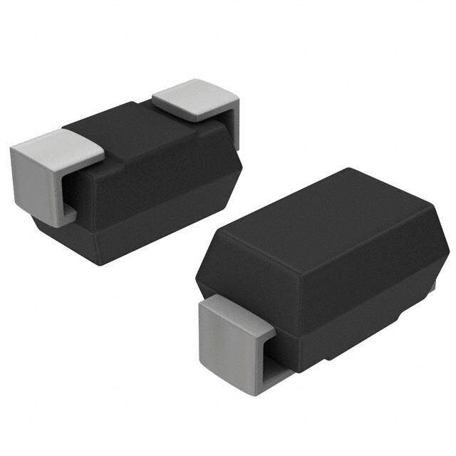
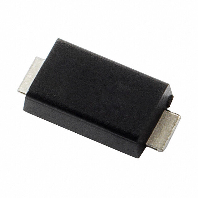
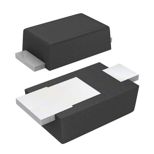
| 描述 | TVS DIODE 10VWM SMDTVS 二极管 - 瞬态电压抑制器 10volts 5uA 88.2 Amps Uni-Dir |
| 产品分类 | |
| 品牌 | Bourns |
| 产品手册 | |
| 产品图片 |
|
| rohs | RoHS 合规性豁免不受无铅要求限制 / 符合限制有害物质指令(RoHS)规范要求 |
| 产品系列 | 二极管与整流器,TVS二极管,TVS 二极管 - 瞬态电压抑制器,Bourns SMCJ10ASMCJ |
| 数据手册 | |
| 产品型号 | SMCJ10A |
| RoHS指令信息 | |
| 不同频率时的电容 | - |
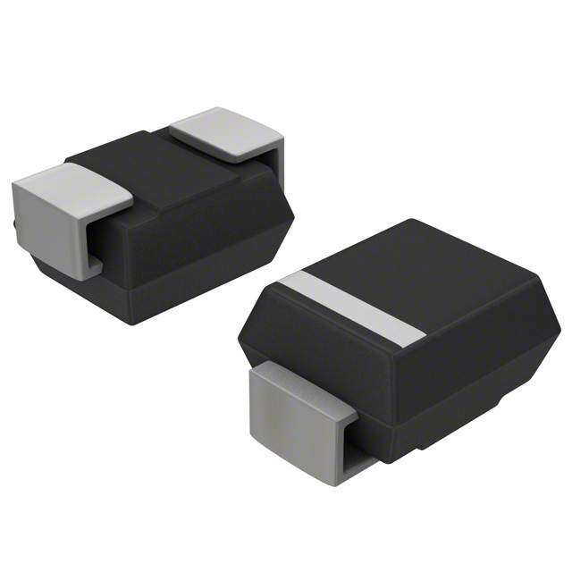
| 产品目录绘图 |
|
| 产品目录页面 | |
| 产品种类 | TVS 二极管 - 瞬态电压抑制器 |
| 供应商器件封装 | SMC (DO-214AB) |
| 其它名称 | SMCJ10ABDKR |
| 击穿电压 | 11.1 V to 12.8 V |
| 功率-峰值脉冲 | 1500W (1.5kW) |
| 包装 | Digi-Reel® |
| 单向通道 | 1 |
| 双向通道 | - |
| 商标 | Bourns |
| 安装类型 | 表面贴装 |
| 安装风格 | SMD/SMT |
| 封装 | Reel |
| 封装/外壳 | DO-214AB,SMC |
| 封装/箱体 | DO-214AB |
| 尺寸 | 5.59 mm W x 7.11 mm L x 2.62 mm H |
| 峰值浪涌电流 | 200 A |
| 峰值脉冲功率耗散 | 1.5 kW |
| 工作温度 | -55°C ~ 150°C |
| 工作电压 | 3.5 V |
| 工厂包装数量 | 3000 |
| 应用 | 通用 |
| 最大工作温度 | + 150 C |
| 最小工作温度 | - 55 C |
| 极性 | Unidirectional |
| 标准包装 | 1 |
| 特色产品 | http://www.digikey.com/product-highlights/cn/zh/bourns-smx-tvs-diodes/1448 |
| 电压-击穿(最小值) | 11.1V |
| 电压-反向关态(典型值) | 10V |
| 电压-箝位(最大值)@Ipp | - |
| 电流-峰值脉冲(10/1000µs) | - |
| 电源线路保护 | 无 |
| 端接类型 | SMD/SMT |
| 类型 | 齐纳 |
| 系列 | SMCJ |


PDF Datasheet 数据手册内容提取
NT *RoHS VCEOARVMSIAPILOLINAASB LE Features Applications NT MPLIA n RoHS compliant* n IEC 61000-4-2 ESD (Min. Level 4) O HS C n Surface Mount SMC package n IEC 61000-4-4 EFT Ro * n Standoff Voltage: 5.0 to 495 volts n IEC 61000-4-5 Surge n Power Dissipation: 1500 watts REE D F LEA SMCJ Transient Voltage Suppressor Diode Series General Information TiBnhoceure rmnassa irnokgfefeltysr s so mTf rapalonlerstrai eebnlleet c Vctrooolmtnaimgc euc onSmiucapptpoiornenessns,t oscLr.VoER EADomRDH SIiSF poORCNuEdOSE teMAiPnsRLIEg Af NoaTr*n sdu vrgidee aon edq EuiSpDm epnrot taercet iochna allpepnlgicinagtio tnhse, sine mcoicmopnadcutc ctohri pin pdaucsktrayg teo DdOev-e2l1o4pA B (SMC) size format. The Transient Voltage Suppressor series offers a choice of Working Peak Reverse Voltage from 5 V up to 495 V and Breakdown Voltage up to 550 V. Typical fast response times are less than 1.0 picosecond for unidirectional devices and less than 5.0 picoseconds for bidirectional devices from 0 V to Minimum Breakdown Voltage. Bourns® Chip Diodes conform to JEDEC standards, are easy to handle with standard pick and place equipment and their flat configuration minimizes roll away. Electrical Characteristics (@ TA = 25 °C Unless Otherwise Noted) Parameter Symbol Value Unit Minimum Peak Pulse Power Dissipation (TP = 1 ms) (Note 1,2) PPK 1500 Watts Peak Forward Surge Current 8.3 ms Single Half Sine Wave Superimposed on Rated Load IFSM 200 Amps (JEDEC Method) (Note 3) Steady State Power Dissipation @ TL = 75 °C PM(AV) 5.0 Watts M(Faoxr imUnuimdi rIencsttiaonntaal nUenoiutss OFnolryw)ard Voltage @ IPP = 100 A SSMMCCJJ51.000AA ~ ~ S SMMCCJJ9409A5 A VF 35..50 Volts Operating Temperature Range TJ -55 to +150 °C Storage Temperature Range TSTG -55 to +150 °C 1. Non-repetitive current pulse, per Pulse Waveform graph and derated above TA = 25 °C per Pulse Derating Curve. 2. Thermal Resistance Junction to Lead. 3. 8.3 ms Single Half-Sine Wave duty cycle = 4 pulses maximum per minute (unidirectional units only). How to Order SMCJ 5.0 CA - H Package SMCJ = SMC/DO-214AB Working Peak Reverse Voltage Asia-Pacific: 5.0 = 5.0 VRWM (Volts) Tel: +886-2 2562-4117 Suffix Email: asiacus@bourns.com A = 5 % Tolerance Unidirectional Device CA = 5 % Tolerance Bidirectional Device Europe: Reel Tel: +36 88 520 390 (blank) = 13 inch reel Email: eurocus@bourns.com -H = 7 inch reel The Americas: Tel: +1-951 781-5500 Email: americus@bourns.com www.bourns.com *RoHS Directive 2002/95/EC Jan. 27, 2003 including annex and RoHS Recast 2011/65/EU June 8, 2011. Specifications are subject to change without notice. The device characteristics and parameters in this data sheet can and do vary in different applications and actual device performance may vary over time. Users should verify actual device performance in their specific applications.
SMCJ Transient Voltage Suppressor Diode Series Electrical Characteristics (@ TA = 25 °C Unless Otherwise Noted) Maximum Maximum Maximum Working Peak Breakdown Voltage Reverse Reverse Reverse Unidirectional Device Bidirectional Device Reverse VBR (Volts) Voltage Leakage Voltage Surge @ VRWM @ IRSM Current Part No. Marking Part No. Marking Min. Max. @ IT (mA) VRWM (V) IR (μA) VRSM (V) IRSM (A) SMCJ5.0A GDE SMCJ5.0CA BDE 6.40 7.00 10 5 800 9.2 163 SMCJ6.0A GDG SMCJ6.0CA BDG 6.67 7.37 10 6 800 10.3 145.7 SMCJ6.5A GDK SMCJ6.5CA BDK 7.22 7.98 10 6.5 500 11.2 134 SMCJ7.0A GDM SMCJ7.0CA BDM 7.78 8.60 10 7 200 12 125 SMCJ7.5A GDP SMCJ7.5CA BDP 8.33 9.21 1 7.5 100 12.9 116.3 SMCJ8.0A GDR SMCJ8.0CA BDR 8.89 9.83 1 8 50 13.6 110.3 SMCJ8.5A GDT SMCJ8.5CA BDT 9.44 10.4 1 8.5 20 14.4 104.2 SMCJ9.0A GDV SMCJ9.0CA BDV 10.0 11.1 1 9 10 15.4 97.4 SMCJ10A GDX SMCJ10CA BDX 11.1 12.3 1 10 5 17 88.3 SMCJ11A GDZ SMCJ11CA BDZ 12.2 13.5 1 11 1 18.2 82.5 SMCJ12A GEE SMCJ12CA BEE 13.3 14.7 1 12 1 19.9 75.4 SMCJ13A GEG SMCJ13CA BEG 14.4 15.9 1 13 1 21.5 69.8 SMCJ14A GEK SMCJ14CA BEK 15.6 17.2 1 14 1 23.2 64.7 SMCJ15A GEM SMCJ15CA BEM 16.7 18.5 1 15 1 24.4 61.5 SMCJ16A GEP SMCJ16CA BEP 17.8 19.7 1 16 1 26 57.7 SMCJ17A GER SMCJ17CA BER 18.9 20.9 1 17 1 27.6 54.4 SMCJ18A GET SMCJ18CA BET 20.0 22.1 1 18 1 29.2 51.4 SMCJ20A GEV SMCJ20CA BEV 22.2 24.5 1 20 1 32.4 46.3 SMCJ22A GEX SMCJ22CA BEX 24.4 26.9 1 22 1 35.5 42.3 SMCJ24A GEZ SMCJ24CA BEZ 26.7 29.5 1 24 1 38.9 38.6 SMCJ26A GFE SMCJ26CA BFE 28.9 31.9 1 26 1 42.1 35.7 SMCJ28A GFG SMCJ28CA BFG 31.1 34.4 1 28 1 45.4 33.1 SMCJ30A GFK SMCJ30CA BFK 33.3 36.8 1 30 1 48.4 31 SMCJ33A GFM SMCJ33CA BFM 36.7 40.6 1 33 1 53.3 28.1 SMCJ36A GFP SMCJ36CA BFP 40 44.2 1 36 1 58.1 25.9 SMCJ40A GFR SMCJ40CA BFR 44.4 49.1 1 40 1 64.5 23.3 SMCJ43A GFT SMCJ43CA BFT 47.8 52.8 1 43 1 69.4 21.7 SMCJ45A GFV SMCJ45CA BFV 50 55.3 1 45 1 72.7 20.6 SMCJ48A GFX SMCJ48CA BFX 53.3 58.9 1 48 1 77.4 19.4 SMCJ51A GFZ SMCJ51CA BFZ 56.7 62.7 1 51 1 82.4 18.2 SMCJ54A GGE SMCJ54CA BGE 60 66.3 1 54 1 87.1 17.3 SMCJ58A GGG SMCJ58CA BGG 64.4 71.2 1 58 1 93.6 16.1 SMCJ60A GGK SMCJ60CA BGK 66.7 73.7 1 60 1 96.8 15.5 SMCJ64A GGM SMCJ64CA BGM 71.1 78.6 1 64 1 103 14.6 SMCJ70A GGP SMCJ70CA BGP 77.8 86.0 1 70 1 113 13.3 SMCJ75A GGR SMCJ75CA BGR 83.3 92.1 1 75 1 121 12.4 SMCJ78A GGT SMCJ78CA BGT 86.7 95.8 1 78 1 126 11.9 SMCJ85A GGV SMCJ85CA BGV 94.4 104 1 85 1 137 11 SMCJ90A GGX SMCJ90CA BGX 100 111 1 90 1 146 10.3 SMCJ100A GGZ SMCJ100CA BGZ 111 123 1 100 1 162 9.3 SMCJ110A GHE SMCJ110CA BHE 122 135 1 110 1 177 8.4 SMCJ120A GHG SMCJ120CA BHG 133 147 1 120 1 193 7.9 SMCJ130A GHK SMCJ130CA BHK 144 159 1 130 1 209 7.2 SMCJ150A GHM SMCJ150CA BHM 167 185 1 150 1 243 6.2 SMCJ160A GHP SMCJ160CA BHP 178 197 1 160 1 259 5.8 SMCJ170A GHR SMCJ170CA BHR 189 209 1 170 1 275 5.5 SMCJ180A GHT SMCJ180CA BHT 201 222 1 180 1 292 5.1 SMCJ200A GHV SMCJ200CA BHV 224 247 1 200 1 324 4.6 SMCJ220A GHX SMCJ220CA BHX 246 272 1 220 1 356 4.2 SMCJ250A GHZ SMCJ250CA BHZ 279 309 1 250 1 405 3.7 SMCJ300A GJE SMCJ300CA BJE 335 371 1 300 1 486 3.1 SMCJ350A GJG SMCJ350CA BJG 391 432 1 350 1 567 2.6 SMCJ400A GJK SMCJ400CA BJK 447 494 1 400 1 648 2.3 SMCJ408A 408A SMCJ408CA 408CA 456 504 1 408 1 658 2.3 SMCJ440A GJM SMCJ440CA BJM 492 543 1 440 1 713 2.1 SMCJ495A 495A SMCJ495CA 495CA 522.5 577.5 1 495 1 760 2.0 Notes: 1. Suffix ‘A’ denotes a 5 % tolerance unidirectional device. 3. For bidirectional devices with a VR of 10 volts or less, the IR limit is double. 2. Suffix ‘CA’ denotes a 5 % tolerance bidirectional device. Specifications are subject to change without notice. The device characteristics and parameters in this data sheet can and do vary in different applications and actual device performance may vary over time. Users should verify actual device performance in their specific applications.
SMCJ Transient Voltage Suppressor Diode Series Product Dimensions Recommended Footprint A A A A B C B B B C C G D Dimension SMC (DO-214AB) 4.69 A (Max.) (0.185) H FC D 3.07 B (Min.) E (0.121) 1.52 C (Min.) F (0.060) Dimension SMC (DO-214AB) MM DIMENSIONS: (I6NC.6HE0S )- 7.11 MM A DIMENSIONS: (0.260 - 0.280) (INCHES) 5.59 - 6.22 B E (0.220 - 0.245) 2.90 - 3.20 Physical Specifications C (0.115 - 0.125) DIMENSIONS: MM Case ...........................................Molded plastic per UL Class 94V-0 0.15 - 0(.I3NC1H ES) D Polarity.......................Cathode band indicates unidirectional device (0.006 - 0.112) No cathode band indicates bidirectional device 7.75 - 8.13 E Weight .............................................................................0.21 grams (0.305 - 0.320) 0.05 - 0.202 F (0.002 - 0.008) 2.00 - 2.62 G (0.079 - 0.103) 0.76 - 1.52 H (0.030 - 0.060) MM DIMENSIONS: (INCHES) Specifications are subject to change without notice. The device characteristics and parameters in this data sheet can and do vary in different applications and actual device performance may vary over time. Users should verify actual device performance in their specific applications.
SMCJ Transient Voltage Suppressor Diode Series Rating & Characteristic Curves 100 s) PulPeak Pulse Derating in Percent ofPeak Pulse Derating in Percent ofPeak Pulse Derating in Percent ofsePeak Power or CurrentPeak Power or CurrentPeak Power or CurrentPeak Pulse Derating in Percent ofPeak Pulse Derating in Percent of Peak Pulse Derating in Percent ofD111Peak Power or CurrentPeak Power or Current75207527520e0Peak Power or Current505005050505000r10100a752075207525050t050500111i505000000n0 xxxg11 101011 2220 0C 00xx555 000 x u10100 2210 0 r2W55WW000bvbb5000yayaya5e550 v v vW0WR0R0R ebebAeAWA.f.fb.yafyaEm5oEm5Eomo vya v.50r.R0.rRrAeb vAebAmAbAmm0R.f.efi.i.Ai.E7mEoem7o7ee .f aE.m5noa.r5nar5nAbAbmsm.strsttAbi .i. m 7 7eTeDT TD Di.a75neae5ne eeeesams5ntmt1m1f1 f f s itTiT0DiD0n0p np npeTeD00ee0eeeeeeemm11dfrefdrdmriia10a0fnnappit0t00nepteueeuu0dederrrr11r1aaedree22at2t uu(5(t55(u°r°r1°1CeeCrC122e )))25((5 °°(511C1C°55C5))000)111555000111777555111777555222000000222000000 MPeak Forward Surge Current (Amps)Peak Forward Surge Current (Amps)Peak Forward Surge Current (Amps)ax12Peak Forward Surge Current (Amps)Peak Forward Surge Current (Amps)1212Peak Forward Surge Current (Amp001i001001m000000000121211112001u001001000000m000111 NS2oS2S2iPiPiPnnnnu(u(gu(gSgJS2J-2lJlllslEsSlREie2PsiPeEenneeD eiDP uD u(Hng Hg eH JWEuWl(ElWgEllsasaJEeaepClClCelseilE iDel fidf dHf Hed e MD MW WSMEtStH StaahhWtEhCie5ile5ailine5 iin fCnfd dt8 t8tl Nti 8eNhMefNhSedtS ht.i. -.hM-3huo3u-ovSti3uoWi5e5WnWh n md mdi 8mde5tm8emNnNe me)ha)at8.).abN-be-3 hubv3uosvsW.vsWeS-e3ue ome medeWmrmrr mda)a u mb boo)vsavos11be1efrfevesf0 0 rer0 gCeC C rooyy 1e1yoffcc10 c0 fClCl0le CeeCyyssscyc u 22 a2alclae0e0ttr0lt se s 6r66 s 22a0ea00 200tat n H 0Ht6H6 zt6z00z0 HH Hzz5z55000555000 111000000111000000 Pulse Waveform Typical Junction Capacitance TR=10 µs Peak value (IRSM) 10000 100 TR=10 µs I, Peak Pulse Current (%)I, Peak Pulse Current (%)I, Peak Pulse Current (%)PPPI, Peak Pulse Current (%)I, Peak Pulse Current (%)P1P11I, Peak Pulse Current (%)P0505050000001105055000000TTT0AAA===TTTT2T22TTPPATPA555RRAP= =P P °T==T°°=22eTTeeCCTP1C1P2a55RaRaP00Pk5P k k==°° He HµeHµvC1C°v1vaasaasCaa0aa0kkllllll fufu fu HµHµ v v ev1eveHvssaaaa a .a a(lla(ll0(lfulfuIlIuIlu u RRfReveve ee aS vaSS=(=(=lalIMIMuMuRRlIIIueeRR)R)S)S=e=2S2S2MSM=IMIMMRR))IdRd2dS2Si2iwiwewses2SesMM.11ca 1ca h0ca hhMddd0as0dasP0dasePePeeieiwy e wy desy resurdxurfdxuidfxs1fwe1scae seisca ehil hiel dne ld ens 101n ass 0 1ca ass P1thePtfettftdeetfeeeoy 0e 0heiasoy e0hioPr0hieurdnxudfdxne fnds d y es 0e e 0ei wri0euwl 5deexl w5fen e5n e ss 1 es 01 ai0 ta0tfdtl pa0etfdpi0nedp0i eeos ei10hiods 0hids tsd tfn e ndw e e d wee ow b0h0 ie% t0eb %wbt %wat5net5ade tha th ahy0e0 haa0ywhaaykhd5p0kedp0ik i v 0 vds aads v3 ( oa( doa Rp0e ( oweRi wRcecTbe %tcds bTt e%ttT.fta fet awf thu.f0 hu. f baPuy .% fhatyPp hEPpkoEIakpotEIohI r rv Payvr ha)Po( ao.)Pkor( or.R)orRr.rr cAe cvT eA tmTAe Satmi( eoSfmiefSRi un.f cue.nf .TPn ntP.pnE.pMfonEIoMIM ur.tfrt PPttP)potE). oort.rI rr rA .A Pm.eS)moi.eS.irrnAn .nm.eSniMMntt.ntt M t..t . 4.0 Capacitance (pF)Capacitance (pF)Capacitance (pF)11Capacitance (pF)1Capacitance (pF)10101Capacitance (pF)00100100100100100000010001000000001100010010000000000000000 BBBiiidddiiBirBrreeBieidcdcciditittririiioeoeorcnecnnUtcUataUaiitololnnlinonniiiddUUnadaiiUlalinrnrrelenieidcdcciditittririiioeoeorcnecnntcataaiitolollionnnaalall TTTAAA ==T=T ATA 222A 5 5=5= = ° °2°2C CC2555 °° CC°C 0 0 00 0 1.0 2.0T, Time (ms)3.0 4.0 0 10 100 1000 0000 1.01.0 2.02.0 3.03.0 4.04.0 0 Pulse Rat1in000g 0Curve 1.01.0 TTT,,, 2 TTT.iTi0Tmimm,,2 eTTe.e 0i i (m(m(mmmeess s(()))mmss))3.03.0 4.04.0 S00t000e5.0a0000dy State Powe111r000 SDS11t0t0aeannSrdSdatoaottafnffinfd n VdVooogfoflf lt ftVa CaVgogoeluet la (tr(agVVvgeoo1e e1l1(tl 00tVs0(s0V0)o0)11olt00lst00s)) 11100000010100000000 TA = 25 °C StanSdtaonffd Vooffl tVaogleta (gVeo l(tVso)lts) 100 Non-repetitive Pulse Waveform W)5.0 P, Peak Power (KW)PP, Peak Power (KW)P, Peak Power (KW)PP110P, Peak Power (KW)1P, Peak Power (KW)01..PP0101P, Peak Power (KW)0010110P0....0100100.01110101. 10110µ01....10100010 0..sµ00100s.1.1 5µ µ.s880s1.. 00m.10 8.m8mm 08.µ.0 0mm. µs10 L 1ms.m e0LL.m0am meeµd maaµs dLdLAs Le er1AAaeae0r1rdadaee 0d sµ aaAA ssµsArr1seer10SaeaN0 hSsSasµ NoNoshµhsnwoosooT-SnSwn1wnrNPNSh-h-e0 n,nrirohoo po10ne eP niowneiw0 p pnnuµP-tw-0ene nir TlrsuPtPst 1etn e iAµiiiTlivTeu1pt0upnts nsiA iieA l0ev0leen= vW ss P Pt e0 t eP =e=eiWµTiP2Tu tu it u P dµiPsAiAW52ulWv2lvaslstusu s5 le5eh1ve°=s=ealale s e.C se vP ° Pv1°0 WW2e2feW eCeCu.ou W 55 0fmfWaalWrlooa s s mvav°°m1rsvereaaeCveCm1m.e vvf0efsWGW.fooee 0f oGroGmrfrfa aroamommrrvmrvpsrmaraee m smhpGpGff 1ohoG1hrr0rra0armm pap mmphh1sh10s0 m mss RM(AV) Steady State Power Dissipation (W)RM(AV) Steady State Power Dissipation (W)RM(AV) Steady State Power Dissipation (W)RM(AV) Steady State Power Dissipation (W)RM(AV) Steady State Power Dissipation (W)RM(AV) Steady State Power Dissipation (55342103421034210............0.....000000000000000050534210034210..34210.....0.....00000000000.....0000000 22552255 550606600I0II5n n n H5H0H6d6dd0z6z0u0uzIuI n0 cnR cRIcR7HHTn7dt dtteiHe5iezLizd5uvuvsvs s z,euceRciRe i i7s sLt ctsR LeLie7ti5Ltetvtvisioesio5ivovaevevisiaaesed ase1 ei1LdLd t sdt 0ooiiTL0oootvv0rireo0araeve1mdad e 1o0od p0or0re0rra11t2u25r5e1 12(2°5C5)115500115500117755117755220000220000 0.1 0µ.s1 µs 1.0 1µ.s0 µs 10 µ1Ts0PT ,Pµ ,Ps PTuuPls,l sePe 1Wu 0Wls0id1ei dtµ 0hWts0h iµdsth 1.0 1m.0s ms 10 m10s ms 0 0 2525 505TT0LL,, LTL7eLe5a,a dLd7 e T5Taeedmm 1Tp0pee0mer1rap0attue0urrraeet 1u( (°2r°Ce5C 1)()2°C5)150150 175175 200200 TP, TPPu,l sPeu Wlseid Wthidth TL, TLLe,a Lde Taedm Tpeemrapteurraet u(°rCe )(°C) Specifications are subject to change without notice. The device characteristics and parameters in this data sheet can and do vary in different applications and actual device performance may vary over time. Users should verify actual device performance in their specific applications.
CSDMDCFJN T5r-a0n5s0ie4nNt -V ToVltSa/gSet eSeurpinpgre Dsisoodre D Aiorrdaey Series Packaging Information The product will be dispensed in tape and reel format (see diagram below). P 0 P1 E T d Index Hole 120 ° F D2 W B D1 D P A C Trailer Device Leader ....... ....... ....... ....... W1 End ....... ....... ....... ....... Start MM DIMENSIONS: (INCHES) 10 pitches (min.) 10 pitches (min.) Devices are packed in accordance with EIA standard Direction of Feed RS-481-A and specifications shown here. Item Symbol SMC (DO-214AB) 7 Inch Reel 13 Inch Reel 6.0 ± 2.0 Carrier Width A (0.236 - 0.079) 8.3 ± 0.20 Carrier Length B (0.327 ± 0.008) 2.5 ± 0.20 Carrier Depth C (0.098 ± 0.008) 1.50 ± 0.10 Sprocket Hole d (0.059 ± 0.004) 178 330 Reel Outside Diameter D (7.008) (12.992) 50.0 Reel Inner Diameter D1 (1.969) MIN. 13.0 +0.50/-0.20 Feed Hole Diameter D2 (0.512 +0.020/-0.008) 1.75 ± 0.10 Sprocket Hole Position E (0.069 ± 0.004) 7.50 ± 0.10 Punch Hole Position F (0.295 ± 0.004) 8.00 ± 0.10 Punch Hole Pitch P (0.315 ± 0.004) 4.00 ± 0.10 Sprocket Hole Pitch P0 (0.157 ± 0.004) 2.00 ± 0.10 Embossment Center P1 (0.079 ± 0.004) 0.30 ± 0.10 Overall Tape Thickness T (0.012 ± 0.004) 16.00 ± 0.30 Tape Width W (0.630 ± 0.012) 22.4 Reel Width W1 (0.882) MAX. Quantity per Reel -- 500 3,000 REV. 06/16 Specifications are subject to change without notice. The device characteristics and parameters in this data sheet can and do vary in different applications and actual device performance may vary over time. Users should verify actual device performance in their specific applications.