ICGOO在线商城 > 分立半导体产品 > 二极管 - 齐纳 - 单 > SMBJ5337B/TR13

 Datasheet下载
- 型号: SMBJ5337B/TR13
- 制造商: American Microsemiconductor, Inc.
- 库位|库存: xxxx|xxxx
- 要求:
| 数量阶梯 | 香港交货 | 国内含税 |
| +xxxx | $xxxx | ¥xxxx |
查看当月历史价格
查看今年历史价格
SMBJ5337B/TR13产品简介:
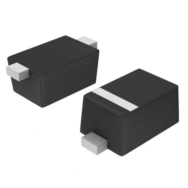
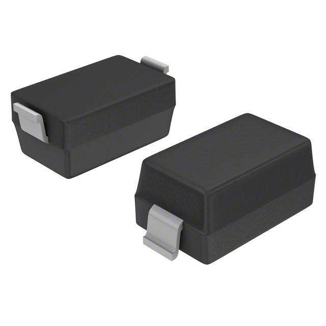
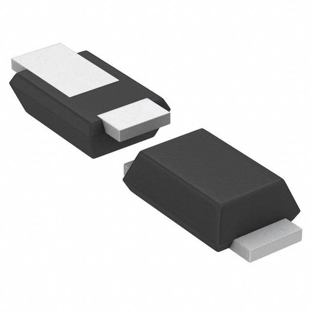
ICGOO电子元器件商城为您提供SMBJ5337B/TR13由American Microsemiconductor, Inc.设计生产,在icgoo商城现货销售,并且可以通过原厂、代理商等渠道进行代购。 SMBJ5337B/TR13价格参考。American Microsemiconductor, Inc.SMBJ5337B/TR13封装/规格:二极管 - 齐纳 - 单, Zener Diode 4.7V 5W ±5% 表面贴装 SMBJ(DO-214AA)。您可以下载SMBJ5337B/TR13参考资料、Datasheet数据手册功能说明书,资料中有SMBJ5337B/TR13 详细功能的应用电路图电压和使用方法及教程。
Microsemi Corporation(现为Microchip子公司)的SMBJ5337B/TR13是一款单齐纳二极管,主要用于电压参考和稳压电路中。该器件广泛应用于需要稳定电压输出和精确电压参考的电子系统中,如电源管理模块、电池充电器、DC-DC转换器、电压监测电路等。

该型号具有SMB(Small Mini Barrier)封装,适用于表面贴装,具备良好的热稳定性和响应速度,适合在空间受限但对性能要求较高的设计中使用。其典型应用包括:

1. 电源稳压电路:为微处理器、传感器、ADC/DAC等提供稳定的参考电压;
2. 电压钳位保护:用于保护敏感电子元件免受电压浪涌或静电放电(ESD)损害;
3. 基准电压源:在精密测量和模拟电路中作为参考电压使用;
4. 工业控制系统:如PLC、仪表、自动化设备中用于提供稳定电压;
5. 消费类电子产品:如智能手机、平板电脑、可穿戴设备中的电源管理部分。

总之,SMBJ5337B/TR13适用于需要高精度电压参考和稳定输出的中低功率应用场景。
| 参数 | 数值 |
| 产品目录 | |
| 描述 | DIODE ZENER 4.7V 5W SMBJ |
| 产品分类 | 单二极管/齐纳 |
| 品牌 | Microsemi Commercial Components Group |
| 数据手册 | http://www.microsemi.com/document-portal/doc_download/124875-lds-0246-2 |
| 产品图片 |
|
| 产品型号 | SMBJ5337B/TR13 |
| rohs | 含铅 / 不符合限制有害物质指令(RoHS)规范要求 |
| 产品系列 | - |
| 不同If时的电压-正向(Vf) | 1.2V @ 1A |
| 不同 Vr时的电流-反向漏电流 | 5µA @ 1V |
| 供应商器件封装 | SMBJ(DO-214AA) |
| 其它名称 | SMBJ5337B/TR13DKR |
| 功率-最大值 | 5W |
| 包装 | Digi-Reel® |
| 安装类型 | 表面贴装 |
| 容差 | ±5% |
| 封装/外壳 | DO-214AA,SMB |
| 工作温度 | -65°C ~ 150°C |
| 标准包装 | 1 |
| 电压-齐纳(标称值)(Vz) | 4.7V |
| 阻抗(最大值)(Zzt) | 2 欧姆 |


- 商务部:美国ITC正式对集成电路等产品启动337调查
- 曝三星4nm工艺存在良率问题 高通将骁龙8 Gen1或转产台积电
- 太阳诱电将投资9.5亿元在常州建新厂生产MLCC 预计2023年完工
- 英特尔发布欧洲新工厂建设计划 深化IDM 2.0 战略
- 台积电先进制程称霸业界 有大客户加持明年业绩稳了
- 达到5530亿美元!SIA预计今年全球半导体销售额将创下新高
- 英特尔拟将自动驾驶子公司Mobileye上市 估值或超500亿美元
- 三星加码芯片和SET,合并消费电子和移动部门,撤换高东真等 CEO
- 三星电子宣布重大人事变动 还合并消费电子和移动部门
- 海关总署:前11个月进口集成电路产品价值2.52万亿元 增长14.8%

PDF Datasheet 数据手册内容提取
SMBJ5333B thru SMBJ5388B Surface Mount Silicon 5 Watt Available Zener Diodes DESCRIPTION The SMBJ5333B - SMBJ5388B series of surface mount 5.0 watt Zeners provides a selection from 3.3 to 200 volts with different tolerances as identified by suffix letter on the part number. It is equivalent to the JEDEC registered 1N5333 thru 1N5388B with identical electrical characteristics and testing. These parts are available with either Sn/Pb plating or a RoHS compliant matte-tin finish. This J-bend design (SMBJ) in the DO-214AA allows for greater PC board mounting density. These plastic encapsulated Zeners have a moisture classification of DO-214AA “Level 1” with no dry pack required. Microsemi also offers numerous other Zener products to J-Bend Package meet higher and lower power applications. NOTE: All SMB series are equivalent to prior SMS package identifications. Important: For the latest information, visit our website http://www.microsemi.com. FEATURES Also available in: • Surface mount equivalent to JEDEC registered 1N5333 thru 1N5388 series. DO-215AA Package • Ideal for high-density and low-profile mounting. (Gull-wing surface mount) • Zener voltage available 3.3 V to 200 V. SMBG5333 – SMBG5388 • Plus/minus 10%, 5% and 2% voltage tolerances are available. (See part nomenclature block.) T-18 Package • RoHS compliant versions available. (axial-leaded) 1N5333 – 1N5388 APPLICATIONS / BENEFITS • Regulates voltage over broad operating current and temperature ranges. • Wide selection from 3.3 to 200 V. • Non-sensitive to ESD per MIL-STD-750 method 1020. • Withstands high surge stresses. • Minimal changes of voltage versus current. • High specified maximum current (I ) with adequate heat sinking. ZM • Moisture classification is “Level 1” per IPC/JEDEC J-STD-020B with no dry pack required. MAXIMUM RATINGS MSC – Lawrence Parameters/Test Conditions Symbol Value Unit 6 Lake Street, Junction and Storage Temperature TJ and TSTG -65 to +150 oC Lawrence, MA 01841 Thermal Resistance Junction-to-Lead R 25 oC/W Tel: 1-800-446-1158 or ӨJL Thermal Resistance Junction-to-Ambient (1) R 90 oC/W (978) 620-2600 ӨJA Off-State Power Dissipation @ 25 oC (2) P 5.0 W Fax: (978) 689-0803 D Forward Voltage @ 1.0 A VF 1.2 V MSC – Ireland Solder Temperature @ 10 s TSP 260 oC Gort Road Business Park, Ennis, Co. Clare, Ireland Notes: 1. When mounted on FR4 PC board (1oz Cu) with recommended footprint (see pad layout). Tel: +353 (0) 65 6840044 2. 5 watts at TL < 25 oC, or 1.38 watts at TA = 25 ºC when mounted on FR4 PC board with recommended Fax: +353 (0) 65 6822298 footprint (also see Figure 1). Website: www.microsemi.com T4-LDS-0246-2, Rev. 1 (120180) ©2012 Microsemi Corporation Page 1 of 5
SMBJ5333B thru SMBJ5388B MECHANICAL and PACKAGING • CASE: Void-free transfer molded thermosetting epoxy body meeting UL94V-0. • TERMINALS: C-bend (modified J-bend) tin-lead or RoHS compliant annealed matte-tin plating solderable per MIL-STD-750, method 2026. • MARKING: Part number without SMBx prefix (e.g. 5334B, 5334Be3, MX5348C, 5376A, etc.). • POLARITY: Cathode indicated by band. Diode to be operated with the banded end positive with respect to the opposite end. • TAPE & REEL option: Standard per EIA-481-1-A with 12 mm tape (add “TR” suffix to part number). Consult factory for quantities. • WEIGHT: 0.1 grams. • See Package Dimensions on last page. PART NOMENCLATURE SMB J 5334 A (e3) Surface Mount Package RoHS Compliance e3 = RoHS Compliant J-Bend Lead Frame Blank = non-RoHS Compliant JEDEC type number Breakdown Voltage Tolerance (See Electrical A = +/- 10% Characteristics table) B = +/- 5% C = +/- 2% SYMBOLS & DEFINITIONS Symbol Definition I Reverse Current: The maximum reverse (leakage) current that will flow at the specified voltage and temperature. R I , I , I Regulator Current: The dc regulator current (I ), at a specified test point (I ), near breakdown knee (I ). Z ZT ZK Z ZT ZK I Maximum Regulator (Zener) Current: The maximum rated dc current for the specified power rating. ZM I Maximum Zener Surge Current: The non-repetitive peak value of Zener surge current at a specified wave form. ZSM V Reverse Voltage: The reverse voltage dc value, no alternating component. R V Zener Voltage: The Zener voltage the device will exhibit at a specified current (I ) in its breakdown region. Z Z Dynamic Impedance: The small signal impedance of the diode when biased to operate in its breakdown region at a Z or Z ZT ZK specified rms current modulation (typically 10% of I or I ) and superimposed on I or I respectively. ZT ZK ZT ZK T4-LDS-0246-2, Rev. 1 (120180) ©2012 Microsemi Corporation Page 2 of 5
SMBJ5333B thru SMBJ5388B ELECTRICAL CHARACTERISTICS @ T = 30oC L REGULATOR TEST MAXIMUM MAXIMUM IR TEST IR TEST MAXIMUM MAXIMUM MAXIMUM VOLTAGE CURRENT DYNAMIC REVERSE VOLTAGE VOLTAGE REGULATOR DYNAMIC SURGE NUTMYPBEE R (VZ) (IZT) I(MA P&E (BZD ZAs)u NfCfiEx CUR(IRRE) NT (Ao( sVnulRyf)f) i x (sB(uV &fRf i)Cx (BC U&(R ICZRM sE)u NfTfix ZIMZKP K@END 1EA.E0N CmEA CU(RIZRSME)N T only) only) only) V mA Ohms µA V V mA Ohms Amps SMBJ5333B 3.3 380 3.0 300 1.0 1.0 1440 400 20 SMBJ5334B 3.6 350 2.5 150 1.0 1.0 1320 500 18.7 SMBJ5335B 3.9 320 2.0 50 1.0 1.0 1220 500 17.6 SMBJ5336B 4.3 290 2.0 10 1.0 1.0 1100 500 16.4 SMBJ5337B 4.7 260 2.0 5.0 1.0 1.0 1010 450 15.3 SMBJ5338B 5.1 240 1.5 1.0 1.0 1.0 930 400 14.4 SMBJ5339B 5.6 220 1.0 1.0 2.0 2.0 865 400 13.4 SMBJ5340B 6.0 200 1.0 1.0 3.0 3.0 790 300 12.7 SMBJ5341B 6.2 200 1.0 1.0 3.0 3.0 765 200 12.4 SMBJ5342B 6.8 175 1.0 10 4.9 5.2 700 200 11.5 SMBJ5343B 7.5 175 1.5 10 5.4 5.7 630 200 10.7 SMBJ5344B 8.2 150 1.5 10 5.9 6.2 580 200 10 SMBJ5345B 8.7 150 2.0 10 6.25 6.6 545 200 9.5 SMBJ5346B 9.1 150 2.0 7.5 6.6 6.9 520 150 9.2 SMBJ5347B 10 125 2.0 5.0 7.2 7.6 475 125 8.6 SMBJ5348B 11 125 2.5 5.0 8.0 8.4 430 125 8.0 SMBJ5349B 12 100 2.5 2.0 8.6 9.1 395 125 7.5 SMBJ5350B 13 100 2.5 1.0 9.4 9.9 365 100 7.0 SMBJ5351B 14 100 2.5 1.0 10.1 10.6 340 75 6.7 SMBJ5352B 15 75 2.5 1.0 10.8 11.5 315 75 6.3 SMBJ5353B 16 75 2.5 1.0 11.5 12.2 295 75 6.0 SMBJ5354B 17 70 2.5 0.5 12.2 12.9 280 75 5.8 SMBJ5355B 18 65 2.5 0.5 13 13.7 264 75 5.5 SMBJ5356B 19 65 3.0 0.5 13.7 14.4 250 75 5.3 SMBJ5357B 20 65 3.0 0.5 14.4 15.2 237 75 5.1 SMBJ5358B 22 50 3.5 0.5 15.8 16.7 216 75 4.7 SMBJ5359B 24 50 3.5 0.5 17.3 18.2 198 100 4.4 SMBJ5360B 25 50 4.0 0.5 18 19 190 110 4.3 SMBJ5361B 27 50 5.0 0.5 19.4 20.6 176 120 4.1 SMBJ5362B 28 50 6.0 0.5 20.1 21.2 170 130 3.9 SMBJ5363B 30 40 8.0 0.5 21.6 22.8 158 140 3.7 SMBJ5364B 33 40 10 0.5 23.8 25.1 144 150 3.5 SMBJ5365B 36 30 11 0.5 25.9 27.4 132 160 3.3 SMBJ5366B 39 30 14 0.5 28.1 29.7 122 170 3.1 SMBJ5367B 43 30 20 0.5 31 32.7 110 190 2.8 SMBJ5368B 47 25 25 0.5 33.8 35.8 100 210 2.7 SMBJ5369B 51 25 27 0.5 36.7 38.8 93 230 2.5 SMBJ5370B 56 20 35 0.5 40.3 42.6 86 280 2.3 SMBJ5371B 60 20 40 0.5 43 45.5 79 350 2.2 SMBJ5372B 62 20 42 0.5 44.6 47.1 76 400 2.1 SMBJ5373B 68 20 44 0.5 49 51.7 70 500 2.0 SMBJ5374B 75 20 45 0.5 54 56 63 620 1.9 SMBJ5375B 82 15 65 0.5 59 62.2 58 720 1.8 SMBJ5376B 87 15 75 0.5 63 66 54.5 760 1.7 SMBJ5377B 91 15 75 0.5 65.5 69.2 52.5 760 1.6 SMBJ5378B 100 12 90 0.5 72 76 47.5 800 1.5 SMBJ5379B 110 12 125 0.5 79.2 83.6 43 1000 1.4 SMBJ5380B 120 10 170 0.5 86.4 91.2 39.5 1150 1.3 SMBJ5381B 130 10 190 0.5 93.6 98.8 36.6 1250 1.2 SMBJ5382B 140 8.0 230 0.5 101 106 34 1500 1.2 SMBJ5383B 150 8.0 330 0.5 108 114 31.6 1500 1.1 SMBJ5384B 160 8.0 350 0.5 115 122 29.4 1650 1.1 SMBJ5385B 170 8.0 380 0.5 122 129 28 1750 1.0 SMBJ5386B 180 5.0 430 0.5 130 137 26.4 1750 1.0 SMBJ5387B 190 5.0 450 0.5 137 144 25 1850 0.9 SMBJ5388B 200 5.0 480 0.5 144 152 23.6 1850 0.9 NOTE 1: Zener voltage (Vz) is measured at TL = 25 oC (+8, -2 oC). Voltage measurement to be performed 40 ±10 milliseconds after application of dc current. NOTE 2: The Zener impedance is derived from 1 kHz ac voltage resulting from an ac current modulation having an rms value equal to 10% of the dc Zener current (I or I ) superimposed on I or I . See MicroNote 202 for Zener impedance variation with different operating ZT ZK ZT ZK currents. NOTE 3: The maximum current (IZM) shown is for a ± 5% tolerance devices. The IZM for other tolerances can be calculated using the formula: I = P/V where V is the V at the high end of the voltage tolerance specified and P is the rated power for the method of mounting. ZM ZM ZM Z NOTE 4: The surge current (IZSM) is specified as the maximum peak of a non-recurrent half-sine wave of 8.3 ms duration. T4-LDS-0246-2, Rev. 1 (120180) ©2012 Microsemi Corporation Page 3 of 5
SMBJ5333B thru SMBJ5388B GRAPHS ) W m ( n o ati p ) si F s p Di e ( r c e n w a Po TL acit m p a u C m xi a M d, TA on FR4 P PC board Temperature (oC) V (Volts) R FIGURE 1 – Power Derating Curve FIGURE 2 – Capacitance vs. Zener Voltage ) F p ( e c n a cit a p a C V (Volts) R FIGURE 3 - Typical Capacitance vs. Reverse Voltage for 5 Watt Zeners T4-LDS-0246-2, Rev. 1 (120180) ©2012 Microsemi Corporation Page 4 of 5
SMBJ5333B thru SMBJ5388B PACKAGE DIMENSIONS Dimensions Ltr Inch Millimeters Min Max Min Max A .077 .083 1.96 2.10 B .160 .180 4.06 4.57 C .130 .155 3.30 3.94 D .205 .220 5.21 5.59 E .077 .104 1.95 2.65 L .030 .060 .760 1.52 PAD LAYOUT INCH mm A .260 6.60 B .085 2.16 C .110 2.79 T4-LDS-0246-2, Rev. 1 (120180) ©2012 Microsemi Corporation Page 5 of 5