ICGOO在线商城 > SL1024B090R

 Datasheet下载
- 型号: SL1024B090R
- 制造商: Littelfuse
- 库位|库存: xxxx|xxxx
- 要求:
| 数量阶梯 | 香港交货 | 国内含税 |
| +xxxx | $xxxx | ¥xxxx |
查看当月历史价格
查看今年历史价格
SL1024B090R产品简介:
ICGOO电子元器件商城为您提供SL1024B090R由Littelfuse设计生产,在icgoo商城现货销售,并且可以通过原厂、代理商等渠道进行代购。 提供SL1024B090R价格参考以及LittelfuseSL1024B090R封装/规格参数等产品信息。 你可以下载SL1024B090R参考资料、Datasheet数据手册功能说明书, 资料中有SL1024B090R详细功能的应用电路图电压和使用方法及教程。
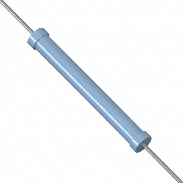
Littelfuse Inc. 的 SL1024B090R 是一款气体放电管避雷器(GDT),主要用于过电压保护。该器件额定直流击穿电压为90V,适用于低频通信线路、电信设备和网络接口等场景。典型应用包括电话线路、DSL调制解调器、有线电视系统(CATV)以及楼宇对讲系统等,可有效防止因雷击或电力线路耦合引起的瞬态过电压损坏敏感电子元件。SL1024B090R 具备高冲击电流承受能力(可达5kA,8/20μs波形),响应速度快,能在微秒级时间内将过电压泄放到地,保障后续电路安全。其密封陶瓷结构确保长期稳定性与可靠性,适合在恶劣环境条件下使用。此外,该GDT常与其他保护器件(如TVS二极管、压敏电阻)配合构成多级保护电路,提升整体防护等级。由于其通流量大、寄生参数小,特别适用于需要高可靠性和长寿命的通信与信号传输接口保护。总体而言,SL1024B090R 广泛应用于工业控制、通信基站、安防系统及家用电器中的防雷与过压防护模块。
| 参数 | 数值 |
| 产品目录 | |
| 描述 | GAS TUBE GDT 90V 20KA RADIAL气体放电管 - GDT /气体等离子体避雷器 90V Omega 3 Terminal |
| 产品分类 | 气体放电管避雷器 (GDT)气体放电管 - GDT /气体等离子体避雷器 |
| 品牌 | Littelfuse |
| 产品手册 | |
| 产品图片 |
|
| rohs | 符合RoHS无铅 / 符合限制有害物质指令(RoHS)规范要求 |
| 产品系列 | Littelfuse SL1024B090RSL1024B |
| 数据手册 | |
| 产品型号 | SL1024B090R |
| 产品种类 | 气体放电管 - GDT /气体等离子体避雷器 |
| 其它名称 | F5441 |
| 包装 | 托盘 |
| 商标 | Littelfuse |
| 安装类型 | 通孔 |
| 安装风格 | Through Hole |
| 容差 | - |
| 封装 | Tray |
| 封装/外壳 | 轴向圆柱形,3引线(径向弯曲) |
| 尺寸 | 8.4 mm D x 11.8 mm L |
| 峰值脉冲电流 | 20 kA |
| 工厂包装数量 | 500 |
| 技术 | Surge Arrester |
| 故障安全保护Y/N | N |
| 故障短接 | 无 |
| 极数 | 3 |
| 标准包装 | 500 |
| 电压-DC火花放电(标称值) | 90V |
| 电压额定值 | 90 V |
| 电极数量 | 3 |
| 电流-AC放电(标称值) | - |
| 直流击穿电压(标称) | 90 V |
| 端接类型 | Radial |
| 系列 | SL1024B |
| 脉冲放电电流(8/20us) | 20kA |


- 商务部:美国ITC正式对集成电路等产品启动337调查
- 曝三星4nm工艺存在良率问题 高通将骁龙8 Gen1或转产台积电
- 太阳诱电将投资9.5亿元在常州建新厂生产MLCC 预计2023年完工
- 英特尔发布欧洲新工厂建设计划 深化IDM 2.0 战略
- 台积电先进制程称霸业界 有大客户加持明年业绩稳了
- 达到5530亿美元!SIA预计今年全球半导体销售额将创下新高
- 英特尔拟将自动驾驶子公司Mobileye上市 估值或超500亿美元
- 三星加码芯片和SET,合并消费电子和移动部门,撤换高东真等 CEO
- 三星电子宣布重大人事变动 还合并消费电子和移动部门
- 海关总署:前11个月进口集成电路产品价值2.52万亿元 增长14.8%


PDF Datasheet 数据手册内容提取
Gas Discharge Tube (GDT) Products SL1021A/B, SL1024A/B and PMT8 Series SL1021A/B, SL1024A/B and PMT8 Series ® Description GDT circuit protection devices dissipate electrical surge energy safely within a contained plasma gas. Commonly used to help protect sensitive telecom and networking equipment and lines, GDTs protect from damage that may result from lightning strikes and equipment switching operations. The Littelfuse GDT series described in this document are available in a variety of leaded and surface mount forms and offered with and without optional fail- safe clip. Please refer to the electrical specifications, dimension and packaging options section of this document for additional information. Agency Approvals SL1021A/B and SL1024A/B Series: SL1021A/B and SL1024A/B series GDTs are designed AGENCY AGENCY FILE NUMBER to offer high levels of performance on fast rising transients in the range of 100V/μS to 1KV/μS, which E128662 ® are those most likely created by induced lightning disturbances. These devices feature ultra low capacitance (typically 3 Electrode GDT Graphical Symbol 1.5pF or less) and are extremely robust with SL102xA devices able to divert a 10,000 Amp pulse without destruction, and SL102xB suffix devices able to divert a b a = TIP a 20,000 Amp pulse without destruction. b = RING e = GROUND These series offer optimized internal geometry which (center electrode) provide low insertion loss at high frequencies, ideal for the protection of broadband and other high speed e transmission equipment. PMT8 Series: Features PMT8 GDT's are telecom grade devices designed to • RoHS compliant • 10KA (A suffix devices) / meet the recommendations in CCITT-K12 and Bellcore • Low insertion loss 20KA (B suffix devices) GR-1361-CORE. The three electrode configuration surge capability tested • Excellent response to is used in applications where simultaneous crowbar with 8/20μs pulse as fast rising transients action of two signal lines is required. defined by IEC 61000-4-5 • Ultra low capacitance • Available with thermal Product Characteristics failsafe option (add ‘F’ suffix to part number) Dull Tin Plate 17.5 ± 12.5 Microns. Materials with ceramic insulator Applications ‘LF’ mark, voltage& date code: Product Marking SL102xA - Red/White text SL1021 / SL1024: PMT8: SL102xB & PMT8 - Blue/White text • Broadband equipment • Telecom network Glow to arc • ADSL equipment interfaces transition current ~ 1Amp • XDSL equipment • Telephone line cards Glow Voltage ~60-200 Volts • Satellite and CATV • Repeaters Storage and Operation -40 to +90°C equipment • Modems Temperature • Splitters • Line test equipment Transverse Voltage < 0.2μSec (Tested to ITU-T Rec. K.12) (Delay Time) • General telecom equipment Arc Voltage ~10 to 35 Volts Holdover Voltage <150mS (Tested to ITU-T Rec. K.12) ©2009 Littelfuse, Inc. 19 SL1021A/B, SL1024A/B and PMT8 Series Specifications are subject to change without notice. Please refer to www.littelfuse.com for current information. Revised: November 10, 2009 Customer should verify actual device performance in their specific applications.
Gas Discharge Tube (GDT) Products SL1021A/B, SL1024A/B and PMT8 Series Electrical Characteristics Device Specifications (at 25°C) Life Ratings DC Voltage DC DC Capaci- Insulation AC Surge Max Max Single Surge Life Part 100V/Sec. Voltage Voltage tance Resistance Current Current Single Surge 10/1000 Number* 100 V/ 1kV/ 50Hz 8/20μSec Surge (@1Mhz) 10/350μSec1 μSecx3001 MIN TYP MAX μSec. μSec. MIN 1Sec.x101 x101 8/20μSec1 SL1021A090 SL1024A090 (cid:2)(cid:3)(cid:4)(cid:3)(cid:4)(cid:5)(cid:6) 4kA2 SL1021B090 72 90 108 650 (cid:7)(cid:8)(cid:9)(cid:5)(cid:10)(cid:4)(cid:11)(cid:12) 5kA3 SL1024B090 PMT 8 090 SL1021A145 SL1024A145 116 145 174 SL1021B145 500 SL1024B145 SL1021A150 600 SL1024A150 120 150 180 SL1021B150 SL1024B150 SL1021A200 150 200 250 SL1021A230 SL1024A230 SL1021B230 184 230 276 450 SL1024B230 PMT 8 230 650 SL1021A250 SL1024A250 SL1021B250 200 250 300 500 SL1024B250 PMT 8 250 SL1021A260 SL1024A260 210 260 310 550 700 SL1021B260 SL1024B260 10kA2 15kA2 <1.5pF 10Amps 200Amps SL1021A300 20kA3 25kA3 SL1024A300 240 300 360 650 850 (cid:2)(cid:3)(cid:4)(cid:3)(cid:4)(cid:5)(cid:6) 2.5kA2 SL1021B300 (cid:7)(cid:8)(cid:9)(cid:5)(cid:3)(cid:4)(cid:4)(cid:11)(cid:12) 5kA3 SL1024B300 SL1021A350 SL1024A350 SL1021B350 280 350 420 700 900 SL1024B350 PMT 8 350 SL1021A400 SL1024A400 SL1021B400 320 400 480 SL1024B400 PMT 8 400 850 950 SL1021A420 SL1024A420 345 420 500 SL1021B420 SL1024B420 SL1021A450 SL1024A450 360 450 540 900 1000 SL1021B450 SL1024B450 SL1021A500 SL1024A500 400 500 600 950 1100 SL1021B500 SL1024B500 SL1021A600 480 600 720 1000 1200 SL1024A600 NOTES: *Max capacitance is 1.5 pF, measured at 1 MHz. 1. Total current through centre electrode, tested in accordance with ITU-T Rec K.12 2. SL A series 3. SL B series & PMT 8 series SL1021A/B, SL1024A/B and PMT8 Series 20 ©2009 Littelfuse, Inc. Specifications are subject to change without notice. Revised: November 10, 2009 Please refer to www.littelfuse.com for current information. Customer should verify actual device performance in their specific applications.
Gas Discharge Tube (GDT) Products SL1021A/B, SL1024A/B and PMT8 Series Time vs. Current for Failsafe Voltage vs. Time Characteristic 60 Max dynamic breakover SL102xA with Failsafe voltage 30 SL102xB or PMT8 500 Volt Higher Melting Point Solder SL102xB or PMT8 350 Volt Higher Melting Point Solder 20 SL102xB or PMT8 90 Volt Higher Melting Point Solder 15 14 11111230 Voltage(V) 9 8 Hold-over voltage 7 6 45 On-State voltage 3 2 1 0 200 400 600 800 1000 1200 0.5 1 2 5 10 15 30 Time (ns) Soldering Parameters - Reflow Soldering (Surface Mount Devices) t Reflow Condition Pb – Free assembly P T P Critical Zone - Temperature Min (T ) 150°C Ramp-up TL to TP s(min) T Pre Heat - Temperature Max (T ) 200°C L t s(max) eT L - Time (Min to Max) (t) 60 – 180 secs ru S(max) Average ramp up rate (Liquidus Tsemp tare Ramp-down (TL) to peak 3°C/second max pme TS(min) tPreheat T to T - Ramp-up Rate 5°C/second max T S S(max) L - Temperature (T) (Liquidus) 217°C Reflow L 25 - Temperature (t) 60 – 150 seconds time to peak temperature Time L (t 25ºC to peak) Peak Temperature (T) 260+0/-5 °C P Time within 5°C of actual peak 10 – 30 seconds Temperature (t) Soldering Parameters - Hand Soldering p Ramp-down Rate 6°C/second max Solder Iron Temperature: 350° C +/- 5°C Time 25°C to peak Temperature (TP) 8 minutes Max. Heating Time: 5 seconds max. Do not exceed 260°C Soldering Parameters - Wave Soldering (Thru-Hole Devices) Recommended Process Parameters: 300 of board 222468000 PreheaWt:ave Parameter Lead-Free Recommendation m side 220200 (Depends on Flux Activation Temperature) (Typical Industry Recommendation) Measured on botto 111110246800000 S o TTPleedrmmeehrpp ePeeaorrtaa tTtt Tuuimerreeme MM:peianrxaimimtuuurmem::: 1162050800-01°°°8 CCC0 sMeacxoinmdusm C) - 80 mperature (° 246000 Solder Dwell Time: 2-5 seconds Te 00 10 20 30 40 50 60 70 80 90 100 110 120 130 140 150 160 170 180 190 200 210 220 230 240 Note: Surge Arrestors with a Failsafe mechanism should be Time (Seconds) individually examined after soldering Preheat Time Cooling Time Dwell Time ©2009 Littelfuse, Inc. 21 SL1021A/B, SL1024A/B and PMT8 Series Specifications are subject to change without notice. Please refer to www.littelfuse.com for current information. Revised: November 10, 2009 Customer should verify actual device performance in their specific applications.
Gas Discharge Tube (GDT) Products SL1021A/B, SL1024A/B and PMT8 Series Device Dimensions NOTE: Failsafe option dimensions shown in green. Shaped Radial Leaded Devices: Surface Mount Devices: Type 04 / R [0.418281. 41±. 8 ±0 .1039] Moun9ti.n0g Area Type 01 / C [01.14.684] Mou[0n9.t3i.n50g4 ]Area [100.4.1604] [08.3.15.4] [100.3.1908] [08.3.119] [0.398] [0.319] 0.3mm Minimum 0.3mm Gap Minimum Gap 9.9 9.9 [0.354] [0.354] 15 [0.590] 16.8 1.0 DIA. MAX. 4.4 [0.661] [0.039] 10.0 ± 0.3 [0.173] [0.394 ± 0.019] Type 60 [0.370.37 ±± 00..3019] [0.Ø2775.0 ± ± 0 0.0.104] 4.4± 0.3 4.4± 0.3 [0.173± 0.12] [0.173± 0.12] [0.41828. 4± ±0 .1039] Mounting Area +80.3.0 [+01.093./23-07/-.00.00] +80.0.0[ 01+9.03/.-1305/.- 000.14] Type 05 / P 11.8 9.0 [0.464] [0.354] 10.10 8.1. [0.398] [0.319] PROFILE VIEW SIDE VIEW TOP VIEW 0.3mm 2.2 ± 0.0 Minimum [0.087 ± 0.000] Gap 9.9 [0.047 1±.2 0 ±.0 00.00] 1[0.2.0 ±47 0 ±.0 0.000] [0.354] 15 6.0 ± 0.0 8.5 ± 0.0 [0.590] [0.236 ± 0.000] [0.335 ± 0.000] 16.8 1.0 DIA. MAX. 4.4 [0.661] [0.039] [0.173] [01.402.735 ± ±0 .00.000] ODOve NraOll TP rEoNdCucRtO SApCaHce 5.5± 0.3 5.5± 0.3 SOLDERING PAD LAYOUT [0.216± 0.12] [0.216± 0.12] Straight "T" Leaded Devices: Straight Radial Leaded Devices: 14.7 [0.579] Type 14 / X [1.96580 ± ± 0 3.118 ] Type 06 / Y [01.14.684] Mou[0n9.t3i.n05g4 ]Area [01.14.684] Mou[0n9.t3i.n50g4 ]Area [100.3.9180] 8.1 D[0I.A3.1 9M]AX. 10.10 [0.398] 8.1 DIA. MAX. 0.3mm [0.319] Minimum Gap Mi0n.i3mmumm 9[0.9.354] Gap 15 [0.590] 2[03..9837] 1[06..6861] 1.0 DIA[.0 M.0A3X9.] 22 [0.866] 1.0 DIA. MAX. [0.039] 6.35 ± 0.5 6.35 ± 0.5 [0.25 ± 0.25] [0.25 ± 0.25] SL1021A/B, SL1024A/B and PMT8 Series 22 ©2009 Littelfuse, Inc. Specifications are subject to change without notice. Revised: November 10, 2009 Please refer to www.littelfuse.com for current information. Customer should verify actual device performance in their specific applications.
Gas Discharge Tube (GDT) Products SL1021A/B, SL1024A/B and PMT8 Series Part Numbering System and Ordering Information Packaging SL102x x xxx x x PMT8 xxx x x Device Type Description Quantity Series Series SL1021 PMT8 Type 01 / C 100pcs/tray x 5 trays per carton 500 SL1024 Type 04 / R 100pcs/tray x 5 trays per carton 500 Surge Capability A = 10kA Type 05 / P 100pcs/tray x 5 trays per carton 500 B = 20kA Breakdown Voltage Breakdown Voltage Type 06 / Y 100pcs/tray x 5 trays per carton 500 090 = 90V 300 = 300V 090 = 90V Type 14 / X 50pcs/tray x 5 trays per carton 250 145 = 145V 350 = 350V 230 = 230V 150 = 150V 400 = 400V 250 = 250V Type 60 500pcs/reel* x 10 reels per carton 5000 200 = 200V 420 = 420V 350 = 350V 230 = 230V 450 = 450V 400 = 400V 250 = 250V 500 = 500V * For tape and reel specifications, please contact factory. 260 = 260V 600 = 600V Configuration Code Configuration Code (See Device Dimensions section) (See Device Dimensions section) C Y 01 10 R S 04 14 P X 05 60 06 Option Code Option Code Blank = No failsafe Blank = No Failsafe F or G = With Failsafe F = With Failsafe ©2009 Littelfuse, Inc. 23 SL1021A/B, SL1024A/B and PMT8 Series Specifications are subject to change without notice. Please refer to www.littelfuse.com for current information. Revised: November 10, 2009 Customer should verify actual device performance in their specific applications.