ICGOO在线商城 > 射频/IF 和 RFID > RF 放大器 > SKY65017-70LF
 Datasheet下载
- 型号: SKY65017-70LF
- 制造商: SKYWORKS
- 库位|库存: xxxx|xxxx
- 要求:
| 数量阶梯 | 香港交货 | 国内含税 |
| +xxxx | $xxxx | ¥xxxx |
查看当月历史价格
查看今年历史价格
SKY65017-70LF产品简介:
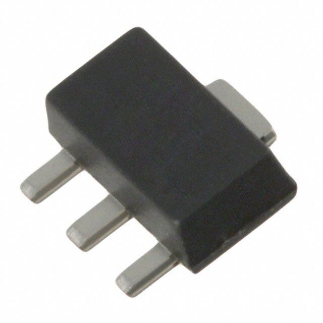
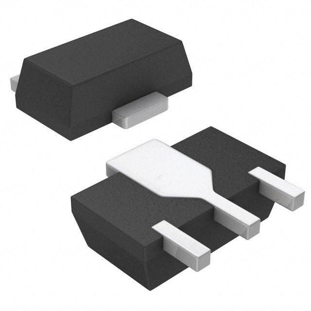
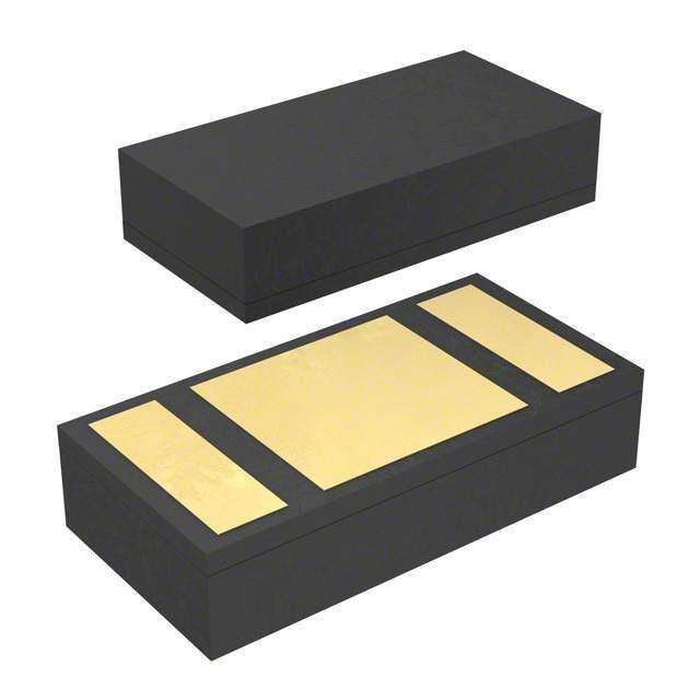
ICGOO电子元器件商城为您提供SKY65017-70LF由SKYWORKS设计生产,在icgoo商城现货销售,并且可以通过原厂、代理商等渠道进行代购。 SKY65017-70LF价格参考¥10.08-¥10.51。SKYWORKSSKY65017-70LF封装/规格:RF 放大器, RF Amplifier IC DBS, HLAN, WLAN 100MHz ~ 6GHz SOT-89-3。您可以下载SKY65017-70LF参考资料、Datasheet数据手册功能说明书,资料中有SKY65017-70LF 详细功能的应用电路图电压和使用方法及教程。
SKY65017-70LF是Skyworks Solutions Inc.生产的一款射频(RF)放大器,属于高性能、低功耗的前端模块,主要应用于无线通信系统中。该器件工作频率范围覆盖700 MHz至1000 MHz,适用于需要高线性度和高效率的射频信号放大场景。

其典型应用场景包括:数字电视广播系统(如ATSC 3.0)、有线电视网络(CATV)、地面数字广播传输设备以及宽带无线基础设施。由于具备良好的增益稳定性和低噪声特性,SKY65017-70LF常用于信号中继、上行链路和下行链路中的信号增强环节,确保在长距离传输中维持信号完整性。

此外,该放大器也广泛用于工业、科学和医疗(ISM)频段设备,以及部分物联网(IoT)网关和远程监控系统中,支持可靠的无线数据传输。其小型化封装(如SOT-143)便于集成到空间受限的电路板中,适合高密度布局设计。

SKY65017-70LF具有出色的抗干扰能力和温度稳定性,可在较宽的工作温度范围内保持性能一致,因此也适用于户外或环境条件较严苛的通信设备。总体而言,这款RF放大器特别适合对信号质量要求较高的中低功率射频应用场合。
| 参数 | 数值 |
| 产品目录 | |
| 描述 | IC AMP INGAP LF-6GHZ SOT-89射频放大器 .1-6.0GHz InGaP HBT Sm Sig Gain 20dB |
| 产品分类 | |
| 品牌 | Skyworks Solutions, Inc. |
| 产品手册 | |
| 产品图片 |
|
| rohs | 符合RoHS无铅 / 符合限制有害物质指令(RoHS)规范要求 |
| 产品系列 | RF集成电路,射频放大器,Skyworks Solutions, Inc. SKY65017-70LF- |
| 数据手册 | |
| P1dB | 20 dBm |
| 产品型号 | SKY65017-70LF |
| RF类型 | DBS,HLAN,WLAN |
| 产品目录页面 | |
| 产品种类 | 射频放大器 |
| 供应商器件封装 | SOT-89-3 |
| 其它名称 | 863-1063-6 |
| 功率增益类型 | 20 dB |
| 包装 | Digi-Reel® |
| 商标 | Skyworks Solutions, Inc. |
| 噪声系数 | 4.5 dB |
| 增益 | 20dB |
| 安装风格 | SMD/SMT |
| 封装 | Reel |
| 封装/外壳 | TO-243AA |
| 封装/箱体 | SOT-89 |
| 工作电源电压 | 5 V |
| 工作频率 | 100 MHz to 6 GHz |
| 工厂包装数量 | 3000 |
| 最大工作温度 | + 85 C |
| 最小工作温度 | - 40 C |
| 标准包装 | 1 |
| 测试频率 | 2 GHz |
| 电压-电源 | 4.5 V ~ 5.5 V |
| 电流-电源 | 120mA |
| 电源电流 | 100 mA |
| 类型 | InGaP Cascadable Amplifier |
| 输出截获点 | 35 dBm |
| 频率 | 0.1Hz ~ 6GHz |


- 商务部:美国ITC正式对集成电路等产品启动337调查
- 曝三星4nm工艺存在良率问题 高通将骁龙8 Gen1或转产台积电
- 太阳诱电将投资9.5亿元在常州建新厂生产MLCC 预计2023年完工
- 英特尔发布欧洲新工厂建设计划 深化IDM 2.0 战略
- 台积电先进制程称霸业界 有大客户加持明年业绩稳了
- 达到5530亿美元!SIA预计今年全球半导体销售额将创下新高
- 英特尔拟将自动驾驶子公司Mobileye上市 估值或超500亿美元
- 三星加码芯片和SET,合并消费电子和移动部门,撤换高东真等 CEO
- 三星电子宣布重大人事变动 还合并消费电子和移动部门
- 海关总署:前11个月进口集成电路产品价值2.52万亿元 增长14.8%


PDF Datasheet 数据手册内容提取
DATA SHEET SKY65017-70LF: 0.1 to 6.0 GHz InGaP Cascadable Amplifier Applications Wireless infrastructure: WLAN, HLAN, DBS, broadband, cellular base stations INPUT OUTPUT Test instrumentation (50 Ω) (50 Ω) Cable television 200528-001 Features Figure 1. SKY65017-70LF Functional Block Diagram Broadband frequency range: 0.1 to 6.0 GHz Description Small signal gain = 20 dB typical @ 2 GHz Skyworks SKY65017-70LF is a general purpose, broadband High OIP3: +33 dBm typical amplifier. The device is fabricated from Skyworks InGaP HBT OP1dB = +20 dBm typical @ 2 GHz process and packaged in a miniature Small Outline Transistor Input and output impedance: 50 Ω nominal (SOT-89) package. Single, positive DC supply voltage The device’s 50 Ω input and output impedance allow it to be easily cascaded without external impedance matching networks. SOT-89 (4-pin, 1.5 x 4.0 mm) package The typical -3 dB bandwidth of the SKY65017-70LF is 0.1 to (MSL1, 260 °C per JEDEC J-STD-020) 6.0 GHz. A functional block diagram is provided in Figure 1. The device package and pinout are shown in Figure 2. Skyworks GreenTM products are compliant with all applicable legislation and are halogen-free. For additional information, refer to Skyworks GND Definition of GreenTM, document number SQ04–0074. 4 1 2 3 INPUT GND OUTPUT 200528-002 Figure 2. SKY65017-70LF Pinout Package (Top View) Skyworks Solutions, Inc. • Phone [781] 376-3000 • Fax [781] 376-3100 • sales@skyworksinc.com • www.skyworksinc.com 200528I • Skyworks Proprietary Information • Products and Product Information are Subject to Change Without Notice • October 17, 2017 1
DATA SHEET • SKY65017-70LF: CASCADABLE AMPLIFIER Electrical and Mechanical Specifications Signal pin assignments and functional pin descriptions are Typical performance characteristics of the SKY65017-70LF are described in Table 1. The absolute maximum ratings of the illustrated in Figures 3 through 6. SKY65017-70LF are provided in Table 2. Electrical specifications are provided in Table 3. Table 1. SKY65017-70LF Signal Descriptions Pin Name Description 1 INPUT RF input with 50 Ω nominal input impedance. An internally generated DC voltage is present at this pin, so an external DC block should be used to connect this pin to the external circuit. 2 GND Ground 3 OUTPUT RF output. DC supply voltage input and RF output with 50 Ω nominal output impedance. The nominal voltage required at this pin is listed in Table 3. Supply current is determined by an external resistor connected between the DC power supply and this pin. 4 GND Ground Table 2. SKY65017-70LF Absolute Maximum Ratings1 Parameter Symbol Minimum Maximum Units Supply voltage VCC 6 V RF input power PIN +10 dBm Supply current ICC 120 mA Power dissipation @ TC = 25 °C PD 510 mW Operating case temperature TC -40 +85 °C Storage temperature TST -65 +125 °C Junction temperature TJ +150 °C Thermal resistance ΘJC 70 °C/W 1 Exposure to maximum rating conditions for extended periods may reduce device reliability. There is no damage to device with only one parameter set at the limit and all other parameters set at or below their nominal values. Exceeding any of the limits listed here may result in permanent damage to the device. ESD HANDLING: Although this device is designed to be as robust as possible, electrostatic discharge (ESD) can damage this device. This device must be protected at all times from ESD when handling or transporting. Static charges may easily produce potentials of several kilovolts on the human body or equipment, which can discharge without detection. Industry-standard ESD handling precautions should be used at all times. Skyworks Solutions, Inc. • Phone [781] 376-3000 • Fax [781] 376-3100 • sales@skyworksinc.com • www.skyworksinc.com 2 October 17, 2017 • Skyworks Proprietary Information • Products and Product Information are Subject to Change Without Notice • 200528I
DATA SHEET • SKY65017-70LF: CASCADABLE AMPLIFIER Table 3. SKY65017-70LF Electrical Specifications1 (IDD = 100 mA, TC = 25 °C, PIN = -10 dBm, Characteristic Impedance [ZO] = 50 Ω, Unless Otherwise Noted) Parameter Symbol Test Conditions Min Typ Max Units Small signal gain |S21| @ 2 GHz 19 20 22 dB 3 dB gain bandwidth2 BW3DB 6 GHz Noise figure2 NF @ 2 GHz 4.5 5.0 dB 1 dB output compression point OP1dB @ 2 GHz +19 +20 dBm Input and output VSWR2 VSWR 0.1 to 5.0 GHz 1.9:1 2.0:1 - Third order output intercept point OIP3 @ 2 GHz, PIN = 0 dBm/tone, Δf = 10 MHz +32 +33 dBm Operating voltage VCC Measured @ P1dB 4.5 5.0 5.5 V Reverse isolation2 |S12| 0.1 to 6.0 GHz 23 dB Gain flatness2 10 MHz to 6 GHz ±1.5 dB 1 Performance is guaranteed only under the conditions listed in this table. 2 Not tested in production. Verified by design. Typical Performance Characteristics (IDD = 100 mA, Characteristic Impedance [Zo] = 50 Ω, Unless Otherwise Noted) 22 0 +25 °C 20 –5 18 –40 °C +85 °C 16 B)–10 dB) 14 n (d Gain ( 11802 Isolatio––2105 –40 °C 246 200528-003 ––2350 +25 °C +85 °C 200528-004 0 1 2 3 4 5 0 1 2 3 4 5 Frequency (GHz) Frequency (GHz) Figure 3. Small Signal Gain vs Frequency Figure 4. Isolation vs Frequency 0 0 –5 –5 B) B) –10 n Loss (d ––1105 n Loss (d ––2105 –40 °C ur +25 °C ur –25 Ret –20 Ret –30 ––2350 +85 °C –40 °C 200528-005 ––4305 +25 °C +85 °C 200528-006 0 1 2 3 4 5 0 1 2 3 4 5 Frequency (GHz) Frequency (GHz) Figure 5. Input Return Loss vs Frequency Figure 6. Output Return Loss vs Frequency Skyworks Solutions, Inc. • Phone [781] 376-3000 • Fax [781] 376-3100 • sales@skyworksinc.com • www.skyworksinc.com 200528I • Skyworks Proprietary Information • Products and Product Information are Subject to Change Without Notice • October 17, 2017 3
DATA SHEET • SKY65017-70LF: CASCADABLE AMPLIFIER Evaluation Board Description The Skyworks SKY65017-70LF Evaluation Board is used to test The Evaluation Board is shipped with L3 in place, which shifts an the performance of the SKY65017-70LF cascadable amplifier. in-band series resonance of the supply decoupling network The Evaluation Board is shown in Figure 7. An Evaluation Board out-of-band. For low-frequency applications, R1 may be used to schematic is shown in Figure 8. Table 4 provides the Bill of conveniently limit supply current on the Evaluation Board. Materials (BOM) for Evaluation Board components. The Evaluation Board also contains a probe fixture that facilitates The input and output of the SKY65017-70LF are connected using the direct measurement of the S-parameters. The probe fixture 50 Ω microstrip transmission lines with DC blocking capacitors, comprises a very short Co-Planar Waveguide (CPW) transmission C1 and C2, to the input and output SMA connectors, respectively. line to pin 1 and an identical line to pin 3. The other two pins of the amplifier are grounded. The CPW transmission lines are The positive supply voltage, VCC, is connected to pin 3 (OUTPUT) compatible with ground-signal-ground wafer probe tips, which of the amplifier using the decoupling network that consists of C4, can be connected to the RF ports of a Vector Network Analyzer L1, L2, and R1. The power supply current, IDD, must be limited (VNA) using coaxial cables. either by the current limit function of an external bench power supply or by replacing L3 with resistor R1, the value of which is The very small electrical length of these CPW transmission lines given in shown in Table 5. obviates the need to de-embed their effects from the S-parameters that are measured. The supply constant current must be applied using the bias tee, which is typically integrated into the VNA, and cascaded with the OUTPUT pin of the amplifier. Figure 7. SKY65017-70LF Evaluation Board Skyworks Solutions, Inc. • Phone [781] 376-3000 • Fax [781] 376-3100 • sales@skyworksinc.com • www.skyworksinc.com 4 October 17, 2017 • Skyworks Proprietary Information • Products and Product Information are Subject to Change Without Notice • 200528I
DATA SHEET • SKY65017-70LF: CASCADABLE AMPLIFIER IDD L2 VSUPPLY C4 L3 R1 L1 C1 C2 VCC INPUT OUTPUT 200528-008 Figure 8. SKY65017-70LF Evaluation Board Schematic Table 4. SKY65017-70LF Evaluation Board Bill of Materials (BOM) Component Value Size Part Number Manufacturer C1, C2, C4 47 nF 0603 GRM188R71E473K Murata L1 33 nH 0603 0603CS-33NX_LU Coilcraft L2 1600 Ω 1810 FBMH4525HM162N-T Taiyo-Yuden L3 110 nH 0805 0805CS-111X_L Coilcraft R1 See Table 5 0603 Variable Variable Table 5. Current Limiting Resistor Values Supply Voltage Value of R1 Minimum Power Dissipation Rating (V) (Ω) (mW) 51 0 - 6 10 250 7 20 500 8 30 500 9 40 1000 10 50 1000 12 70 2000 1 To ensure that the supply current does not exceed the recommended value, a regulated current source should be used to supply the device under this condition. Skyworks Solutions, Inc. • Phone [781] 376-3000 • Fax [781] 376-3100 • sales@skyworksinc.com • www.skyworksinc.com 200528I • Skyworks Proprietary Information • Products and Product Information are Subject to Change Without Notice • October 17, 2017 5
DATA SHEET • SKY65017-70LF: CASCADABLE AMPLIFIER Package Dimensions Package and Handling Information Typical part markings for the SKY65017-70LF are shown in Instructions on the shipping container label regarding exposure Figure 9. The PCB layout footprint for the SKY65017-70LF is to moisture after the container seal is broken must be followed. provided in Figure 10. Package dimensions are provided in Otherwise, problems related to moisture absorption may occur Figure 11, and tape and reel dimensions are shown in when the part is subjected to high temperature during solder Figure 12. assembly. The SKY65017-70LF is rated to Moisture Sensitivity Level 1 (MSL1) at 260 C. It can be used for lead or lead-free soldering. For additional information, refer to the Skyworks Application Note, Solder Reflow Information, document number 200164. Care must be taken when attaching this product, whether it is done manually or in a production solder reflow environment. Production quantities of this product are shipped in a standard tape and reel format. Skyworks Part Number YY = Calendar Year SK17 WW = Work Week YYWW 200528-009 Figure 9. SKY65017-70LF Typical Part Markings Skyworks Solutions, Inc. • Phone [781] 376-3000 • Fax [781] 376-3100 • sales@skyworksinc.com • www.skyworksinc.com 6 October 17, 2017 • Skyworks Proprietary Information • Products and Product Information are Subject to Change Without Notice • 200528I
DATA SHEET • SKY65017-70LF: CASCADABLE AMPLIFIER 1.73 2X 1.50 R0.254 Typ 0.86 Exposed Soldering 2.70 Area Typ 4.55 Pin 1 1.40 0.42 0.42 0.50 200528-010 Figure 10. SKY65017-70LF PCB Layout Footprint –Y– –T– 4.5 ± 0.1 1.5 ± 0.1 R0.254 Typ 1.73 +0.10/–0.11 0.40 +0.04/–0.05 Half Etching Depth 0.100 7 4.10 ± 0.15 1.1010/–0.20 1 2 3 2.5 +0.1/–0.2 –Z– 2.20 +0.09/–0.0 3 2 1 0. + 0.5 ± 0.06 Pin 1 End View Bottom View 2X 0.42 ± 0.06 0.10 M T Z S Y S Top View 7° Typ Notes: 1. All measurements are in millimeters. 2. Dimensioning and tolerancing according to ASME Y14.5M-1994. 3. Package dimension does not include mold protrusions or gate burrs. 1.50 BSC Mold protrusions and gate burrs do not exceed 0.005” per end. Body width dimension does not include interlead mold protrusions. 3.00 BSC Interlead protrusions do not exceed 0.005” per side. 4. Leadwidth dimension does not include dambar protrusions. Side View Allowable protrusion does not exceed 0.002” total in excess of lead width dimension at maximum material condition. 200528-011 Figure 11. SKY65017-70LF Package Dimensions Skyworks Solutions, Inc. • Phone [781] 376-3000 • Fax [781] 376-3100 • sales@skyworksinc.com • www.skyworksinc.com 200528I • Skyworks Proprietary Information • Products and Product Information are Subject to Change Without Notice • October 17, 2017 7
DATA SHEET • SKY65017-70LF: CASCADABLE AMPLIFIER 2.00 ± 0.05 4.00 (See Note 7) ∅1.50 +0.1 –0.0 ∅1.50 Min 0.30 ± 0.05 8.00 A 1.75 ± 0.10 R0.20 Max 1.65 5.50 ± 0.05 4.80 (Bo) 12.0 + 0.3 –0.1 R 0.3 Typ A 5.10 (Ao) 1.90 (Ko) 4.20 (A1) Notes: 1. Carrier tapes must meet all requirements of Skyworks GP01-D233 procurement spec for tape and reel shipping. 2. Carrier tape material: black conductive polycarbonate or polystyrene. 3. Cover tape material: transparent conductive PSA. Cover tape size: 9.2 mm width. 4. Typical ESD surface resistivity must meet all ESD requirements of Skyworks specified in GP01-D233. 5. Ao and Bo measurement point to be 0.30 mm from bottom pocket. 6. All measurements are in millimeters. 200528-012 7. 10-sprocket hole pitch cumulative tolerance 0.2 mm. Figure 12. SKY65017-70LF Tape and Reel Dimensions Skyworks Solutions, Inc. • Phone [781] 376-3000 • Fax [781] 376-3100 • sales@skyworksinc.com • www.skyworksinc.com 8 October 17, 2017 • Skyworks Proprietary Information • Products and Product Information are Subject to Change Without Notice • 200528I
DATA SHEET • SKY65017-70LF: CASCADABLE AMPLIFIER Ordering Information Model Name Ordering Part Number Evaluation Board Part Number SKY65017-70LF: Cascadable Low-Noise Amplifier SKY65017-70LF SKY65017-70LF-EVB Copyright © 2002-2006, 2012-2013, 2016-2017 Skyworks Solutions, Inc. All Rights Reserved. Information in this document is provided in connection with Skyworks Solutions, Inc. (“Skyworks”) products or services. These materials, including the information contained herein, are provided by Skyworks as a service to its customers and may be used for informational purposes only by the customer. Skyworks assumes no responsibility for errors or omissions in these materials or the information contained herein. Skyworks may change its documentation, products, services, specifications or product descriptions at any time, without notice. Skyworks makes no commitment to update the materials or information and shall have no responsibility whatsoever for conflicts, incompatibilities, or other difficulties arising from any future changes. No license, whether express, implied, by estoppel or otherwise, is granted to any intellectual property rights by this document. Skyworks assumes no liability for any materials, products or information provided hereunder, including the sale, distribution, reproduction or use of Skyworks products, information or materials, except as may be provided in Skyworks Terms and Conditions of Sale. THE MATERIALS, PRODUCTS AND INFORMATION ARE PROVIDED “AS IS” WITHOUT WARRANTY OF ANY KIND, WHETHER EXPRESS, IMPLIED, STATUTORY, OR OTHERWISE, INCLUDING FITNESS FOR A PARTICULAR PURPOSE OR USE, MERCHANTABILITY, PERFORMANCE, QUALITY OR NON-INFRINGEMENT OF ANY INTELLECTUAL PROPERTY RIGHT; ALL SUCH WARRANTIES ARE HEREBY EXPRESSLY DISCLAIMED. SKYWORKS DOES NOT WARRANT THE ACCURACY OR COMPLETENESS OF THE INFORMATION, TEXT, GRAPHICS OR OTHER ITEMS CONTAINED WITHIN THESE MATERIALS. SKYWORKS SHALL NOT BE LIABLE FOR ANY DAMAGES, INCLUDING BUT NOT LIMITED TO ANY SPECIAL, INDIRECT, INCIDENTAL, STATUTORY, OR CONSEQUENTIAL DAMAGES, INCLUDING WITHOUT LIMITATION, LOST REVENUES OR LOST PROFITS THAT MAY RESULT FROM THE USE OF THE MATERIALS OR INFORMATION, WHETHER OR NOT THE RECIPIENT OF MATERIALS HAS BEEN ADVISED OF THE POSSIBILITY OF SUCH DAMAGE. Skyworks products are not intended for use in medical, lifesaving or life-sustaining applications, or other equipment in which the failure of the Skyworks products could lead to personal injury, death, physical or environmental damage. Skyworks customers using or selling Skyworks products for use in such applications do so at their own risk and agree to fully indemnify Skyworks for any damages resulting from such improper use or sale. Customers are responsible for their products and applications using Skyworks products, which may deviate from published specifications as a result of design defects, errors, or operation of products outside of published parameters or design specifications. Customers should include design and operating safeguards to minimize these and other risks. Skyworks assumes no liability for applications assistance, customer product design, or damage to any equipment resulting from the use of Skyworks products outside of stated published specifications or parameters. Skyworks and the Skyworks symbol are trademarks or registered trademarks of Skyworks Solutions, Inc.or its subsidiaries in the United States and other countries. Third-party brands and names are for identification purposes only, and are the property of their respective owners. Additional information, including relevant terms and conditions, posted at www.skyworksinc.com, are incorporated by reference. Skyworks Solutions, Inc. • Phone [781] 376-3000 • Fax [781] 376-3100 • sales@skyworksinc.com • www.skyworksinc.com 200528I • Skyworks Proprietary Information • Products and Product Information are Subject to Change Without Notice • October 17, 2017 9