ICGOO在线商城 > 开发板,套件,编程器 > 评估和演示板和套件 > S5U13781R00C10M
 Datasheet下载
- 型号: S5U13781R00C10M
- 制造商: EPCOS
- 库位|库存: xxxx|xxxx
- 要求:
| 数量阶梯 | 香港交货 | 国内含税 |
| +xxxx | $xxxx | ¥xxxx |
查看当月历史价格
查看今年历史价格
S5U13781R00C10M产品简介:
ICGOO电子元器件商城为您提供S5U13781R00C10M由EPCOS设计生产,在icgoo商城现货销售,并且可以通过原厂、代理商等渠道进行代购。 S5U13781R00C10M价格参考。EPCOSS5U13781R00C10M封装/规格:评估和演示板和套件, S1D13781 LCD Controller Display Evaluation Board。您可以下载S5U13781R00C10M参考资料、Datasheet数据手册功能说明书,资料中有S5U13781R00C10M 详细功能的应用电路图电压和使用方法及教程。
型号为S5U13781R00C10M、由Epson Electronics America Inc-Semiconductor Div生产的评估和演示板,主要用于评估其配套的实时时钟(RTC)或低功耗计时芯片的性能与功能。该评估板适用于需要高精度时间保持和低功耗运行的嵌入式系统开发场景。

典型应用包括工业控制设备、医疗仪器、通信设备、消费类电子产品以及汽车电子系统等对时间精度和可靠性要求较高的领域。通过该评估板,工程师可以快速测试芯片的振荡稳定性、电池备份功能、I²C通信接口性能以及在宽温度范围内的运行表现。

此外,该套件支持原型设计与软件调试,便于开发人员验证电路设计、优化功耗管理策略,并加速产品从研发到量产的进程。其模块化设计简化了与主控MCU的连接,配合详细的用户手册和技术资料,有助于缩短开发周期,提升研发效率。

总之,S5U13781R00C10M评估板是一款面向高可靠性实时计时应用的开发工具,适用于各类需精准时间管理的电子系统研发。
| 参数 | 数值 |
| 产品目录 | 编程器,开发系统嵌入式解决方案 |
| 描述 | BOARD EVAL BOOSTERPACK S1D13781显示开发工具 S1D13781 BoosterPack LCDC Development Pkg |
| 产品分类 | |
| 品牌 | Epson ICsEpson Electronics America Inc-Semiconductor Div |
| 产品手册 | |
| 产品图片 |
|
| rohs | 符合RoHS无铅 / 符合限制有害物质指令(RoHS)规范要求 |
| 产品系列 | 光电开发工具,显示开发工具,Epson ICs S5U13781R00C10M- |
| 数据手册 | |
| 产品型号 | S5U13781R00C10MS5U13781R00C10M |
| 主要属性 | - |
| 主要用途 | 显示器,LCD 控制器 |
| 产品 | Starter Kits |
| 产品种类 | 显示开发工具 |
| 使用的IC/零件 | S1D13781 |
| 商标 | Epson ICs |
| 封装 | Bulk |
| 嵌入式 | - |
| 工作电源电压 | 2.7 V to 3.6 V |
| 工具用于评估 | S1D13781 |
| 所含物品 | 2 个板 |
| 接口类型 | SPI |
| 标准包装 | 1 |
| 特色产品 | http://www.digikey.com/product-highlights/cn/zh/epson-electronics-s1d13781-graphics-controller/2824 |
| 相关产品 | /product-detail/zh/LM4F232H5BBFIGR/LM4F232H5BBFIGR-ND/3675134/product-detail/zh/LM4F232H5QCFIG/296-34953-ND/3661887/product-detail/zh/EK-LM4F120XL/296-34897-ND/3601071/product-detail/zh/NHD-4.3-480272EF-ATXL%23-T/NHD-4.3-480272EF-ATXL%23-T-ND/3597748/product-detail/zh/S1D13781F00A100/S1D13781F00A100-ND/2811381/product-detail/zh/LX4F232H5QDFIGA3/296-30293-ND/2799337/product-detail/zh/LX4F232H5QCFIGA3/296-30292-ND/2799336/product-detail/zh/LX4F231H5QRFIGA3/296-30294-ND/2799335/product-detail/zh/NHD-3.5-320240MF-ATXL%23-1/NHD-3.5-320240MF-ATXL%23-1-ND/2165878 |
| 系列 | S5U13781 |
| 辅助属性 | - |


- 商务部:美国ITC正式对集成电路等产品启动337调查
- 曝三星4nm工艺存在良率问题 高通将骁龙8 Gen1或转产台积电
- 太阳诱电将投资9.5亿元在常州建新厂生产MLCC 预计2023年完工
- 英特尔发布欧洲新工厂建设计划 深化IDM 2.0 战略
- 台积电先进制程称霸业界 有大客户加持明年业绩稳了
- 达到5530亿美元!SIA预计今年全球半导体销售额将创下新高
- 英特尔拟将自动驾驶子公司Mobileye上市 估值或超500亿美元
- 三星加码芯片和SET,合并消费电子和移动部门,撤换高东真等 CEO
- 三星电子宣布重大人事变动 还合并消费电子和移动部门
- 海关总署:前11个月进口集成电路产品价值2.52万亿元 增长14.8%
PDF Datasheet 数据手册内容提取
S5U13781R00C10M User Manual Document Number: X94A-G-008-01 Status: Revision 1.0 Issue Date: 2012/09/25 SEIKO EPSON CORPORATION Rev. 1.0
Page 2 Evaluation board/kit and Development tool important notice 1. This evaluation board/kit or development tool is designed for use for engineering evaluation, demonstration, or development purposes only. Do not use it for other purpose. It is not intended to meet the requirement of design for finished product. 2. This evaluation board/kit or development tool is intended for use by an electronics engineer, and it is not a consumer product. The user should use these goods properly and safely. Seiko Epson dose not assume any responsibility and liability of any kind of damage and/or fire caused by usage of it. The user should cease to use it when any abnormal issue occurs, even during proper and safe use. 3. The parts used for this evaluation board/kit or development tool may change without notice. NOTICE No part of this material may be reproduced or duplicated in any form or by any means without the written permission of Seiko Epson. Seiko Epson reserves the right to make changes to this material without notice. Seiko Epson does not assume any liability of any kind arising out of any inaccuracies contained in this material or due to its application or use in any product or circuit and, further, there is no representation that this material is applicable to products requiring high level reliability, such as, medical products. Moreover, no license to any intellectual property rights is granted by implication or otherwise, and there is no representation or warranty that anything made in accordance with this material will be free from any patent or copyright infringement of a third party. This material or portions thereof may contain technology or the subject relating to strategic products under the control of the Foreign Exchange and Foreign Trade Law of Japan and may require an export license from the Ministry of Economy, Trade and Industry or other approval from another government agency. All brands or product names mentioned herein are trademarks and/or registered trademarks of their respective companies. ©SEIKO EPSON CORPORATION 2012, All rights reserved. S5U13781R00C10M User Manual X94A-G-008-01 Revision 1.0 Issue Date: 2012/09/25 Seiko Epson Corporation
Page 3 Table of Contents 1 Introduction ......................................................................................................................... 4 2 LCD Module Options and Parts Lists .................................................................................. 6 3 Connecting the Boards........................................................................................................ 7 4 StellarisWare Drivers and Demo Software .........................................................................10 4.1 Requirements .............................................................................................................................. 10 4.1.1 Hardware Requirements ..................................................................................................... 10 4.1.2 Software Requirements ....................................................................................................... 10 4.2 Software Installation .................................................................................................................... 10 4.3 Software Description ................................................................................................................... 12 4.3.1 Driver Software .................................................................................................................... 12 4.3.2 Demonstration Software ...................................................................................................... 13 4.4 Software Modification .................................................................................................................. 13 4.5 Software License ......................................................................................................................... 13 5 Stellaris LM4F120 Launchpad Connections .......................................................................14 6 Pinout for 40-Pin LCD Interface .........................................................................................16 7 Pinout for 54-Pin LCD Interface .........................................................................................18 8 S5U13781M00C100 Schematics .......................................................................................22 9 S5U13781M00C100 Board Layout.....................................................................................26 10 References ........................................................................................................................30 11 Change Record ..................................................................................................................31 X94A-G-008-01 S5U13781R00C10M User Manual Issue Date: 2012/09/25 Revision 1.0 Seiko Epson Corporation
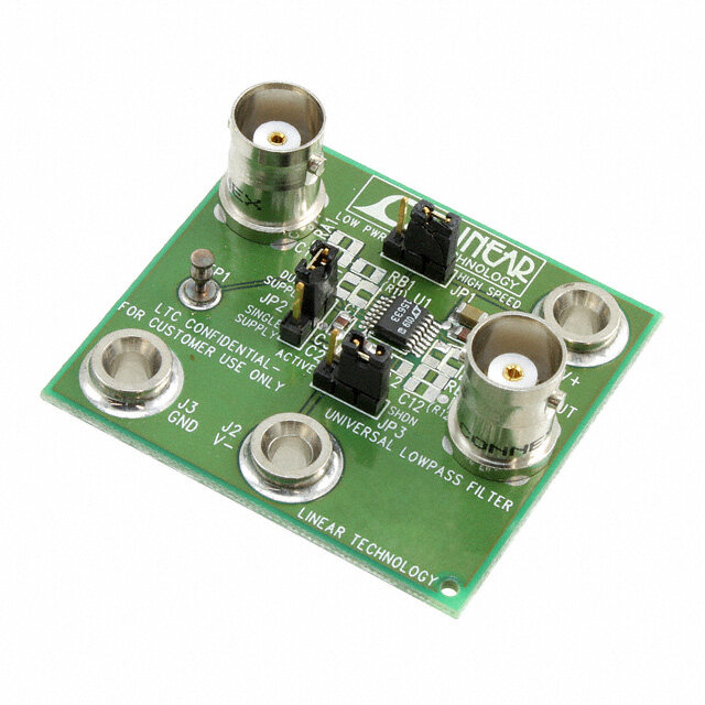
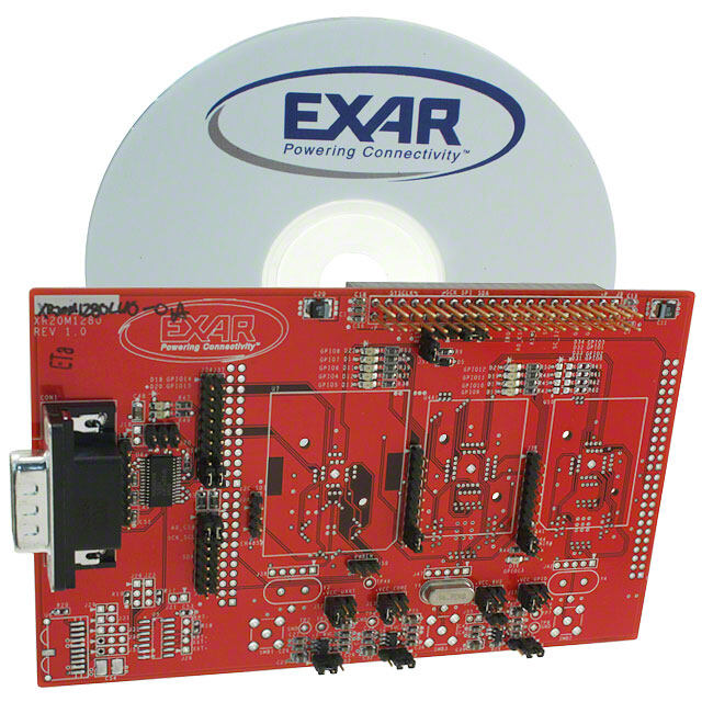
Page 4 1 Introduction The S5U13781R00C10M is the S1D13781 BoosterPack LCDC Development Package. It is a BoosterPack board set for TI’s Stellaris LM4F120 Launchpad for evaluating and developing embedded LCD display applications using the Epson S1D13781 LCD Controller IC. The S5U13781R00C10M consists of the following two items: S5U13781R00C100 Reference Board Set S5U13781M00C100 Signal Adapter Board Set Figure 1 shows a picture of the S5U13781R00C100 Reference Board Set. Figure 1 – S5U13781R00C100 Reference Board Set The S5U13781R00C100 Reference Board Set consists of two break-off sub-boards: Main board which has the S1D13781 LCD Controller, 2Mbytes of Serial Flash, DC/DC converter for LED backlight, 2x25 connector for Host interface (J4), and 2x25 connector for LCD interface (J5). LCD interface board which has a 54-pin FPC (flexible printed circuit) connector (J8) to connect to LCD module and 0.1”-pitch 2x25+2x6 connectors (J9 and J10). For more information about the S5U13781R00C100, please refer to the “S5U13781R00C100 Reference Board User Manual”, document number X94A-G-004-01 S5U13781R00C10M User Manual X94A-G-008-01 Revision 1.0 Issue Date: 2012/09/25 Seiko Epson Corporation
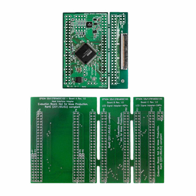
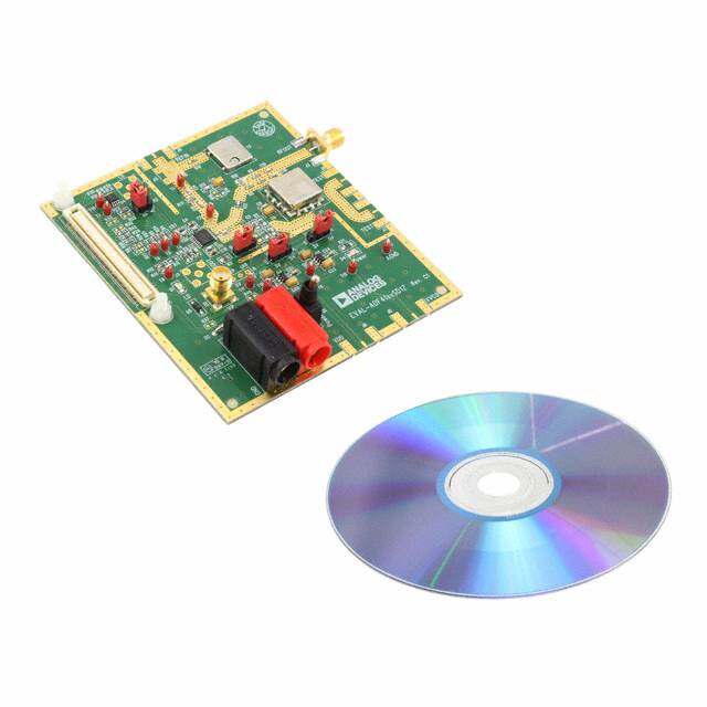
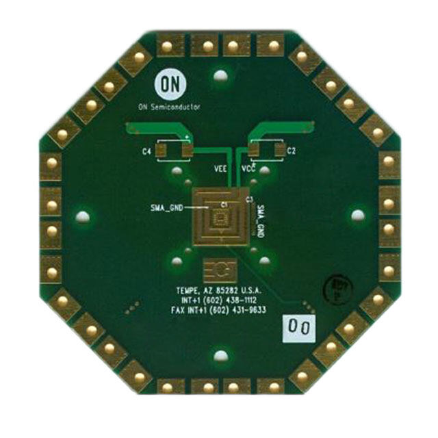
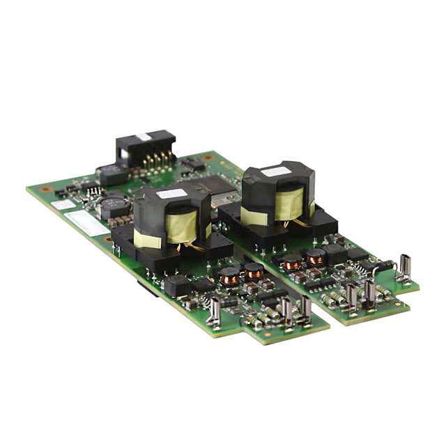
Page 5 Figure 2 shows a picture of the S5U13781M00C100 Signal Adapter Board Set. Figure 2 – S5U13781M00C100 Signal Adapter Board Set The S5U13781M00C100 Signal Adapter Board Set is a supplement to the S5U13781R00C100 Reference Board Set and it consists of three break-off sub-boards (schematics and layout are in Sections 8 and 9): “Board A – Host Interface Adapter” is used to adapt the S5U13781R00C100 Main Board’s Host Interface signals (P5) to the Stellaris LM4F120 Launchpad BoosterPack connectors (P1 to P4), and it also routes the S5U13781R00C100 Main Boards’ LCD Interface signals (P9) to a connector (J2) for connecting to either “Board B – LCD Signal Adapter – 40Pin” or “Board C – LCD Signal Adapter – 54Pin”. “Board B – LCD Signal Adapter – 40Pin” provides signal routing for connecting to an LCD module with a 40-pin FPC (4.3” WQVGA). One side (PB1) connects to J2 of Board A and the other side (PB2) connects to J9 of the S5U13781R00C100 LCD interface board. “Board C – LCD Signal Adapter – 54Pin” provides signal routing for connecting to an LCD module with a 54-pin FPC (3.5” QVGA). One side (PC1) connects to J2 of Board A and the other side (PC2+PC3) connects to J9+J10 of the S5U13781R00C100 LCD interface board. This user manual is updated as appropriate. Please check the Seiko Epson Website at http://www.epson.jp/device/semicon_e/product/lcd_controllers/index.htm for the latest revision of this document before beginning any development. We appreciate your comments on our documentation. Please contact us via email at documentation@erd.epson.com. X94A-G-008-01 S5U13781R00C10M User Manual Issue Date: 2012/09/25 Revision 1.0 Seiko Epson Corporation
Page 6 2 LCD Module Options and Parts Lists The S5U13781R00C10M development package can interface to two types of LCD modules. One type of LCD module has a 40-pin FPC interface (4.3” WQVGA display) and the other type has a 54-pin FPC interface (3.5” QVGA). The boards in the S5U13781R00C10M package do not come with any header/receptacle connectors installed. These connectors will have to be purchased separately and soldered to the boards by the end- user. The following table shows the two LCD module options and their parts list (with manufacturer part numbers): 40-Pin Interface 54-Pin Interface Manufacturer Part Number S5U13781R00C10M 1 1 Epson S5U13781R00C10M 2x25, 0.1”-pitch header 4 4 3M 961250-6404-AR 2x25, 0.1”-pitch receptacle 4 4 3M 929975-01-25-RK 2x10, 0.1”-pitch receptacle 2 2 3M 929975-01-10-RK 2x3, 0.1”-pitch header - 1 3M 929836-01-03-RK 2x3, 0.1”-pitch receptacle - 1 3M 929975-01-03-RK 54-Pin, 3.5”, QVGA LCD - 1 Newhaven Display NHD-3.5-320240MF-ATXL#-1 or Hantronix HDA351-LV Evervision VGG322425-6UFLWA or Topway LMT035KDH03 or Tianma TM035KDH03 or All Shore ASI-T-350EA3NN/D or Powertip PH320240T-006-I-Q or Ampire AM320240L2TMQW-TB0H or Logic Tech. LTTD320240035-L1RT or US Micro USMP-TT035Q-01D or Tech Toys LVC75Z779V2S or Microtips MTF-TQ35SP741-AV 40-Pin, 4.3”, WQVGA LCD 1 - Newhaven Display NHD-4.3-480272EF-ATXL#(-T) or All Shore ASI-T-430FA6NT/H or AZ Displays ATM0430D5(-T) or Logic Tech. LTTD480272043-L1 or Tianma TM043NBH02 NOTE: The Stellaris LM4F120 Launchpad board is not included in the parts list and will have to be purchased separately if the end-user does not already have one. S5U13781R00C10M User Manual X94A-G-008-01 Revision 1.0 Issue Date: 2012/09/25 Seiko Epson Corporation
Page 7 3 Connecting the Boards Figure 3 shows the board connections diagram (side view) for the S5U13781R00C10M BoosterPack LCDC Development Package. S5U13781R00C100 S5U13781R00C100 S5U13781M00C100 LCD Interface Board Main Board Board A J5 P9 J4 J2 J8 P5 J9 P1 J10 P3 P4 P2 LCD Module J1 PC3 J3 J4 PB2 or J2 PC2 PB1 or S5U13781M00C100 Stellaris LM4F120 PC1 Board B or Launchpad Board C Board (Side View) Figure 3 – Board Connections Diagram The Stellaris LM4F120 Launchpad board has 2x10 headers on the top side for J1/J3 and J2/J4. J8 of the S5U13781R00C100 LCD Interface Board is an FPC connector with bottom side contacts. The FPC of the LCD module should be inserted into J8 with contacts facing down and pin 1 lined up with the pin 1 edge of J8 (see Figure 4). J8 Pin 1 FPC Pin 1 (contacts face down) Figure 4 – J8 FPC Connection Example for 40-Pin LCD Module X94A-G-008-01 S5U13781R00C10M User Manual Issue Date: 2012/09/25 Revision 1.0 Seiko Epson Corporation
Page 8 STEPS FOR ASSEMBLING S5U13781R00C10M DEVELOPMENT PACKAGE Modification to Stellaris LM4F120 Launchpad Board 1) On the Stellaris LM4F120 Launchpad board, remove (de-solder) resistors R9 and R10. This disconnects the short-circuits between GPIO ports PB6/PD0 and PB7/PD1. Soldering of Header and Receptacles 2) On the S5U13781R00C100 Main Board, connect pins 3 and 4 of J3 (solder a wire across the two pins or solder a header with shunt jumper) to set the current of the backlight LED driver to 20mA. The Newhaven 3.5” display is rated at 20mA typical and the Newhaven 4.3” display is rated at 32mA typical. (Current drive can be increased in steps of 20mA by shorting pins 5-6 and pins 7- 8 of J3.) 3) On the S5U13781R00C100 Main Board, connect pins 1 and 2 of J1 (solder a wire across the two pins or solder a header with shunt jumper) to connect power for the Serial Flash. 4) On the bottom side of the S5U13781R00C100 Main Board, install and solder 2x25 headers for J4 and J5. 5) On the top side of the S5U13781M00C100 Board A, install and solder 2x25 receptacles for P5 and P9. 6) On the bottom side of the S5U13781M00C100 Board A, install and solder 2x10 receptacles for P1+P3 and P2+P4. (Note that P1 and P3 together make up one 2x10 receptacle and P2 and P4 together make up the other 2x10 receptacle.) 7) On the bottom side of the S5U13781M00C100 Board A, install and solder a 2x25 header for J2. 8) For a 40-pin (4.3”, WQVGA) LCD module, use S5U13781M00C100 Board B and install (on the top side) 2x25 receptacles for PB1 and PB2. For a 54-pin (3.5”, QVGA) LCD module, use S5U13781M00C100 Board C and install (on the top side) 2x25 receptacles for PC1 and PC2 as well as a 2x3 receptacle for PC3. 9) On the bottom side of the S5U13781R00C100 LCD Interface Board, install and solder a 2x25 header for J9. If using a 54-pin LCD module, a 2x3 header for J10 should also be installed and soldered on the bottom side of the S5U13781R00C100 LCD Interface Board. S5U13781R00C10M User Manual X94A-G-008-01 Revision 1.0 Issue Date: 2012/09/25 Seiko Epson Corporation
Page 9 Assembly of Boards 10) Plug the bottom 2x10 receptacles of S5U13781M00C100 Board A to the Stellaris LM4F120 Launchpad 2x10 headers. Make sure the pin 1s of P1-P4 of S5U13781M00C100 Board A line up with pin1s of J1-J4 of the Stellaris LM4F120 Launchpad. 11) Plug the bottom headers (J4, J5) of S5U13781R00C100 Main Board to the top side receptacles (P5, P9) of S5U13781M00C100 Board A. Make sure the pin 1s of J4 and J5 of the S5U13781R00C100 Main Board line up with the pin1s of P5 and P9 of S5U13781M00C100 Board A. 12) Plug the 2x25 receptacle (PB1/PC1) of S5U13781M00C100 Board B/C to J2 (2x25 header) on the bottom side of S5U13781M00C100 Board A. Make sure pin 1 of J2 of S5U13781M00C100 Board A lines up with pin 1 of PB1/PC1 of S5U13781M00C100 Board B/C. 13) Plug the bottom headers (J9, J10) of the S5U13781R00C100 LCD Interface Board to the top side receptacles (PB2/PC2, PC3) of S5U13781M00C100 Board B/C. 14) Connect the LCD module’s FPC to J8 of the S5U13781R00C100 LCD Interface Board. Make sure the pads/contacts side of the FPC are facing down and pin 1 of the FPC lines up with the pin 1 edge of J8 (please refer to Figure 4). X94A-G-008-01 S5U13781R00C10M User Manual Issue Date: 2012/09/25 Revision 1.0 Seiko Epson Corporation
Page 10 4 StellarisWare Drivers and Demo Software The S1D13781 BoosterPack LCDC Development Package was developed with a companion software package that is available from the Epson website at vdc.epson.com. This software package includes a S1D13781 demonstration application and graphics library driver software source code intended for use in combination with TI StellarisWare and the Stellaris LM4F120 Launchpad. 4.1 Requirements 4.1.1 Hardware Requirements The S1D13781 BoosterPack LCDC Development Package software was developed for use with the following hardware. Stellaris LM4F120 Launchpad S5U13781R00C10M Compatible LCD Display For details on preparing the hardware for use, see Section Error! Reference source not found., Error! ference source not found.. 4.1.2 Software Requirements The S1D13781 BoosterPack LCDC Development Package software was developed for use with the following software tools. Code Composer Studio – see http://www.ti.com/tool/ccstudio StellarisWare – see http://www.ti.com/stellaris ICDI USB drivers (for debugging) – see http://www.ti.com/tool/stellaris_icdi_drivers 4.2 Software Installation The following steps are required to install the S1D13781 BoosterPack LCDC Development Package software and the required software tools. If the TI software tools have already been installed, skip to step 4. Note: The following instructions assume a PC running Windows XP (or higher). For compatibility with other operating systems or development platforms, please refer to TI’s website at http://www.ti.com/stellaris. 1. Install the Code Composer Studio IDE. 2. Install StellarisWare 3. Connect the Launchpad to the PC via a USB connector. When prompted, install the Stellaris ICDI drivers. On some systems, the drivers must be manually installed using the Windows Device Manager. 4. Extract the S1D13781 BoosterPack software into the StellarisWare working folder for the Launchpad board model being used (i.e. C:/StellarisWare/boards/ek-lm4f120xl/). 5. Open Code Composer Studio. S5U13781R00C10M User Manual X94A-G-008-01 Revision 1.0 Issue Date: 2012/09/25 Seiko Epson Corporation
Page 11 6. Select Import Project from the TI Resource Explorer or Import… > Code Composer Studio > Existing CCS Eclipse Projects from the File Menu. The following window will appear. 7. Browse to the folder where the S1D13781 BoosterPack software is installed (i.e. C:/StellarisWare/boards/ek-lm4f120xl/BoosterPack_S1D13781/) and click OK. 8. The s1d13781_demo project should now be shown in the “Discovered Projects” list. Select s1d13781_demo and click Finish. 9. The s1d13781_demo project should now be listed in the CCS Project Explorer. X94A-G-008-01 S5U13781R00C10M User Manual Issue Date: 2012/09/25 Revision 1.0 Seiko Epson Corporation
Page 12 4.3 Software Description The S1D13781 BoosterPack LCDC Development Package software consists of the 2 parts: driver software and demonstration software. 4.3.1 Driver Software Drivers are required to integrate the S1D13781R00C reference board into the Stellaris Launchpad environment. Several drivers are required to support the S1D13781 LCDC functions, integrate the S1D13781 into the StellarisWare development system, and interface to the Serial Flash memory included on the S5U13781R00C100 reference board. S1D13781 LCDC Driver source code is provided that supports the main features of the S1D13781. The source code is found in the “./BoosterPack_S1D13781/drivers” folder and supports features such as: (see “readme.txt” file) SPI Host interface (used to connect with the Stellaris MCU). This includes low level functions such as register and memory read/write access and initialization of the S1D13781. Main Layer configuration PIP Layer configuration Alpha Blend, Transparency, Rotation, PIP modes, etc. The “S1D13781.h” file defines register initialization values for the 3.5” and 4.3” LCD modules. Each type of LCD module has a “#define xxxxx_PANEL” macro in the “Panel/System Selection” section of “S1D13781.h”. Only one should be uncommented and the rest commented out. For example, to select 4.3” LCD module, uncomment “#define WQVGA_PANEL” and comment out “#define QVGA_PANEL”. The specific features supported may change without notice and may be added to as additional functionality is required. StellarisWare Integration Driver source code is provided that integrates the SD1D13781 drivers and the StellarisWare graphics library. The following functions, as defined in the StellarisWare structure tDisplay, are supported: Draw Single Pixel Draw Multiple Pixels Draw a Horizontal Line Draw a Vertical Line Draw a Filled Rectangle 24-bit RGB to Display Color Translation Flush Cached Drawing For details on these functions, refer to the StellarisWare graphics library (see grlib.h). S5U13781R00C10M User Manual X94A-G-008-01 Revision 1.0 Issue Date: 2012/09/25 Seiko Epson Corporation
Page 13 Serial Flash Memory Driver source code is provided that supports read/write access to the 2MByte serial flash memory included on the S5U13781R00C reference board. The driver also supports other IO functions common to a serial flash memory device. 4.3.2 Demonstration Software Source code for an application that demonstrate the main features of the S1D13781 LCDC is contained in the “./BoosterPack_S1D13781/s1d13781_demo” folder. The purpose of this application is twofold: it provides a working example of the main features of the S1D13781 LCDC it provides source code which the user can utilize as the starting point to programming the S1D13781 LCDC from within the TI StellarisWare development system Feature Support The demonstration application source code provides example implementation for the following S1D13781features. S1D13781 initialization Serial flash initialization Drawing to the Main Layer Drawing to the PIP Layer (including PIP position, PIP rotation, PIP transparency, and various PIP modes (i.e. fade, blink, etc.)) Alpha Blend (including various blend levels) Backlight control The specific features supported may change without notice and may be added to as additional functionality is required. 4.4 Software Modification Once all the tools and components are setup and configured, the Code Composer Studio IDE allows modification, building, and debugging of the source code. All source code developed for the S1D13781 BoosterPack LCDC Development Package is provided “as is” and may be modified and/or re-used in developing applications for use with the S5U13781R00C10M. 4.5 Software License For license information about the source code developed for the S1D13781 BoosterPack LCDC Development Package, see the copyright information included in the source code. X94A-G-008-01 S5U13781R00C10M User Manual Issue Date: 2012/09/25 Revision 1.0 Seiko Epson Corporation
Page 14 5 Stellaris LM4F120 Launchpad Connections The following tables show the signals of the Stellaris LM4F120 Launchpad connectors which are used by the S5U13781R00C10M BoosterPack LCDC Development Package: J1 Stellaris LM4F120 S1D13781 LCDC Launchpad Signal BoosterPack Usage 1 VCC (3.3V) VCC (3.3V) 2 PB5/AIN1/SSI2Fss/T1CCP1/CAN0Tx SPI1_CS# 3 PB0/U1Rx/T2CCP0 - 4 PB1/U1Tx/T2CCP1 - 5 PE4/AIN9/U5Rx/I2C2SCL/CAN0Rx - 6 PE5/AIN8/U5Tx/I2C2SDA/CAN0Tx - 7 PB4/AIN10/SSI2Clk/T1CCP0/CAN0Rx SPI1_CLK 8 PA5/SSI0Tx SPI2_SIMO 9 PA6/I2C1SCL - 10 PA7/I2C1SDA - J2 Stellaris LM4F120 S1D13781 LCDC Launchpad Signal BoosterPack Usage 1 GND GND 2 PB2/I2C0SCL/T3CCP0 LED_CTRL 3 PE0/AIN3/U7Rx - 4 PF0/U1RTS/SSI1Rx/CAN0Rx/T0CCP0/ - NMI/C0o 5 RESET# - 6 PB7/SSI2Tx/T0CCP1 SPI1_SIMO 7 PB6/SSI2Rx/C0CCP0 SPI1_SOMI 8 PA4/SSI0Rx SPI2_SOMI 9 PA3/SSI0Fss SPI2_CS# 10 PA2/SSI0Clk SPI2_CLK J3 Stellaris LM4F120 S1D13781 LCDC Launchpad Signal BoosterPack Usage 1 VBUS (5.0V) - 2 GND GND 3 PD0/AIN7/SSI3Clk/SSI1Clk/I2C3SCL/ MIO0* WT2CCP0 4 PD1/AIN6/SSI3Fss/SSI1Fss/I2C3SDA/ MIO1* WT2CCP1 5 PD2/AIN5/SSI3Rx/SSI1Rx/WT3CCP0 MIO2* 6 PD3/AIN4/SSI3Tx/SSI1Tx/WT3CCP1 MIO3* 7 PE1/AIN2/U7Tx MIO4* 8 PE2/AIN1 - 9 PE3/AIN0 - 10 PF1/U1CTS/SSI1Tx/T0CCP1/C1o/TRD1 SPI3_SIMO *MIOx signals are multi-function, depending what type of LCD module is connected. Demo firmware and drivers currently do not support these signals. S5U13781R00C10M User Manual X94A-G-008-01 Revision 1.0 Issue Date: 2012/09/25 Seiko Epson Corporation
Page 15 J4 Stellaris LM4F120 S1D13781 LCDC Launchpad Signal BoosterPack Usage 1 PF2/SSI1Clk/T1CCP0/TRD0 SPI3_CLK 2 PF3 /SSI1Fss/CAN0Tx/T1CCP1/TRCLK SPI3_CS# 3 PB3/I2C0SDA/T3CCP1 - 4 PC4/C1-/U4Rx/U1Rx/WT0CCP0/U1RTS - 5 PC5/C1+/U4Tx/U1Tx/WT0CCP1/U1CTS - 6 PC6/C0+/U3Rx/WT1CCP0 - 7 PC7/C0-/U3Tx/WT1CCP1 - 8 PD6/U2Rx/WT5CCP0 - 9 PD7/U2Tx/WT5CCP1/NMI - 10 PF4/T2CCP0 - The SPI1_* signals are the SPI interface signals for the S1D13781 LCD Controller on the S5U13781R00C100 Main Board. The SPI2_* signals are the SPI interface signals for the M25P16 Serial Flash (2Mbytes) on the S5U13781R00C100 Main Board. The LED_CTRL signal is for controlling (by pulse-width modulation) the LED backlight current (LED+, LED- signals to the LCD module). The LED backlight driver circuit is on the S5U13781R00C100 Main Board. The MIO* signals are multi-function signals which can be used for resistive touch interface, SPI interface to LCD module’s LCD driver chip, or general-purpose I/O. They are mainly intended to support variations in pinout of various 54-pin LCD modules (see Section 6 and 7). Currently, demo firmware and drivers do not support or make use of these signals. The SPI3_* signals are intended to be used as the SPI interface to the LCD driver chip on some 54-pin LCD modules (see Section 6 and 7). Currently, demo firmware and drivers do not support or make use of these signals. X94A-G-008-01 S5U13781R00C10M User Manual Issue Date: 2012/09/25 Revision 1.0 Seiko Epson Corporation
Page 16 6 Pinout for 40-Pin LCD Interface The following table shows the pinout and signal connections of the 40-pin FPC: Newhaven Display Stellaris LM4F120 S5U13781R00C100 NHD-4.3-480272EF-ATXL# Launchpad Main Board FPC Pin NHD-4.3-480272EF-ATXL#-T Connection Connection 1 LED- - J5-47,48 2 LED+ - J5-45,46 3 GND GND GND 4 VDD (3.3V) VDD (3.3V) VDD (3.3V) 5 R0 - J5-25 6 R1 - J5-26 7 R2 - J5-27 8 R3 - J5-28 9 R4 - J5-29 10 R5 - J5-30 11 R6 - J5-31 12 R7 - J5-32 13 G0 - J5-17 14 G1 - J5-18 15 G2 - J5-19 16 G3 - J5-20 17 G4 - J5-21 18 G5 - J5-22 19 G6 - J5-23 20 G7 - J5-24 21 B0 - J5-9 22 B1 - J5-10 23 B2 - J5-11 24 B3 - J5-12 25 B4 - J5-13 26 B5 - J5-14 27 B6 - J5-15 28 B7 - J5-16 29 GND GND GND 30 PCLK - J5-6 31 DISPEN - J5-49 (S1D13781 GPIO0 output) 32 HSYNC - J5-4 33 VSYNC - J5-3 34 DE - J5-5 35 - - - 36 GND GND GND 37 XR* J3-4 (PD1/AIN6) - 38 YD* J3-3 (PD0/AIN7) - 39 XL* J3-6 (PD3/AIN4) - 40 YU* J3-7 (PE1/AIN2) - *Optional resistive touch analog voltages. S5U13781R00C10M User Manual X94A-G-008-01 Revision 1.0 Issue Date: 2012/09/25 Seiko Epson Corporation
Page 17 In addition to the Newhaven NHD-4.3-480272EF-ATXL#[-T], the following LCD modules from other manufacturers are also supported by the 40-pin hardware pinout: All Shore ASI-T-430FA6NT/H AZ Displays ATM0430D5 (ATM0430D5-T for resistive touch screen option) Logic Technologies LTTD480272043-L1 Tianma TM043NBH02 Demo firmware and drivers only support LCD timings for Newhaven NHD-4.3-480272EF-ATXL#[-T]. The other LCD modules may have different timings and might require different programming values for the S1D13781 registers. The 4 resistive touch analog signals are routed from the 40-pin FPC of the LCD module to the Stellaris LM4F120 Launchpad analog input ports, but there is currently no demo firmware and driver provided for the touch interface. X94A-G-008-01 S5U13781R00C10M User Manual Issue Date: 2012/09/25 Revision 1.0 Seiko Epson Corporation
Page 18 7 Pinout for 54-Pin LCD Interface The following table shows the pinout and signal connections of the 54-pin FPC: Stellaris LM4F120 S5U13781R00C100 Newhaven Display Launchpad Main Board FPC Pin NHD-3.5-320240MF-ATXL#-1 Connection Connection 1 LED- - J5-47,48 2 LED- - J5-47,48 3 LED+ - J5-45,46 4 LED+ - J5-45,46 5 - - - 6 - *J3-5 (PD2/SSI3Rx) - 7 - - - 8 RST# *J3-7 (PE1/AIN2) - 9 SPI_CS# *J3-4 (PD1/AIN6) - 10 SPI_CLK *J3-3 - (PD0/AIN7/SSI3Clk) 11 SPI_SIMO *J3-6 - (PD3/AIN4/SSI3Tx) 12 B0 - J5-9 13 B1 - J5-10 14 B2 - J5-11 15 B3 - J5-12 16 B4 - J5-13 17 B5 - J5-14 18 B6 - J5-15 19 B7 - J5-16 20 G0 - J5-17 21 G1 - J5-18 22 G2 - J5-19 23 G3 - J5-20 24 G4 - J5-21 25 G5 - J5-22 26 G6 - J5-23 27 G7 - J5-24 28 R0 - J5-25 29 R1 - J5-26 30 R2 - J5-27 31 R3 - J5-28 32 R4 - J5-29 33 R5 - J5-30 34 R6 - J5-31 35 R7 - J5-32 36 HSYNC - J5-4 37 VSYNC - J5-3 38 PCLK - J5-6 39 - - - 40 - - - 41 VDD (3.3V) VDD (3.3V) VDD (3.3V) 42 VDD (3.3V) VDD (3.3V) VDD (3.3V) 43 - *J4-2 (PF3) - 44 - - - 45 - - - S5U13781R00C10M User Manual X94A-G-008-01 Revision 1.0 Issue Date: 2012/09/25 Seiko Epson Corporation
Page 19 47 - - - 48 - - - 49 - *J4-1 (PF2/SSI1Clk) - 50 - *J3-10 (PF1/SSI1Tx) - 51 - - - 52 DE - J5-5 53 GND GND GND 54 GND GND GND *These are multi-function signals depending on the LCD module connected. Demo firmware and drivers currently do not support these signals. In addition to the Newhaven NHD-3.5-320240MF-ATXL#-1, the following LCD modules from other manufacturers are also supported by the 54-pin hardware pinout: Hantronix HDA351-LV Evervision VGG322425-6UFLWA Topway LMT035KDH03 Tianma TM035KDH03 All Shore ASI-T-350EA3NN/D Powertip PH320240T-006-I-Q AMP/Ampire AM320240L2TMQW-TB0H Logic Technologies LTTD320240035-L1RT US Micro USMP-TT035Q-01D TechToys LVC75Z779V2S Microtips MTF-TQ35SP741-AV Demo firmware and drivers only support LCD timings for the Newhaven NHD-3.5-320240MF-ATXL#- 1. The other LCD modules may have different timings and might require different programming values for the S1D13781 registers. The following table shows the pinouts of the different variations of the 54-pin FPC connection of LCD modules from the various manufacturers: X94A-G-008-01 S5U13781R00C10M User Manual Issue Date: 2012/09/25 Revision 1.0 Seiko Epson Corporation
Page 20 Topway Logic Technologies LMT035KDH03 LTTD320240035-L1RT Tianma US Micro TM035KDH03 USMP-TT035Q-01D Hantronix Newhaven TechToys HDA351-LV NHD-3.5-320240MF-ATXL#-1 AMP / Ampire LVC75Z779V1S / Evervision All Shore Powertip Microtips AM320240L2TMQ FPC Pin VGG322425-6UFLWA ASI-T-350EA3NN/D PH320240T-006-I-Q W-TB0H MTF-TQ35SP741-AV 1 LED- LED- LED- LED- LED- 2 LED- LED- LED- LED- LED- 3 LED+ LED+ LED+ LED+ LED+ 4 LED+ LED+ LED+ LED+ LED+ 5 - - - - - 6 - - - SPI_SOMI RST# 7 - - - - - 8 RST# RST# RST# RST# YU* 9 - SPI_CS# SPI_CS# SPI_CS# XR* 10 - SPI_CLK SPI_CLK SPI_CLK YD* 11 - SPI_SIMO SPI_SIMO SPI_SIMO XL* 12 B0 B0 B0 B0 B0 13 B1 B1 B1 B1 B1 14 B2 B2 B2 B2 B2 15 B3 B3 B3 B3 B3 16 B4 B4 B4 B4 B4 17 B5 B5 B5 B5 B5 18 B6 B6 B6 B6 B6 19 B7 B7 B7 B7 B7 20 G0 G0 G0 G0 G0 21 G1 G1 G1 G1 G1 22 G2 G2 G2 G2 G2 23 G3 G3 G3 G3 G3 24 G4 G4 G4 G4 G4 25 G5 G5 G5 G5 G5 26 G6 G6 G6 G6 G6 27 G7 G7 G7 G7 G7 28 R0 R0 R0 R0 R0 29 R1 R1 R1 R1 R1 30 R2 R2 R2 R2 R2 31 R3 R3 R3 R3 R3 32 R4 R4 R4 R4 R4 33 R5 R5 R5 R5 R5 34 R6 R6 R6 R6 R6 35 R7 R7 R7 R7 R7 36 HSYNC HSYNC HSYNC HSYNC HSYNC 37 VSYNC VSYNC VSYNC VSYNC VSYNC 38 PCLK PCLK PCLK PCLK PCLK 39 - - - - - 40 - - - - - 41 VDD VDD VDD VDD VDD 42 VDD VDD VDD VDD VDD 43 - - VDD - SPI_CS# 44 - - VDD - - 45 - - - - - 47 - - - - - 48 - - - - - S5U13781R00C10M User Manual X94A-G-008-01 Revision 1.0 Issue Date: 2012/09/25 Seiko Epson Corporation
Page 21 49 - - - - SPI_CLK 50 - - - - SPI_SIMO 51 - - - - - 52 - DE DE DE DE 53 GND GND GND GND GND 54 GND GND GND GND GND *Optional resistive touch analog voltages. The SPI interface is optional if the application firmware desires to control the LCD driver chip inside the LCD module. Most applications don’t need this control and just rely on the default settings of the LCD driver chip. X94A-G-008-01 S5U13781R00C10M User Manual Issue Date: 2012/09/25 Revision 1.0 Seiko Epson Corporation
Page 22 8 S5U13781M00C100 Schematics S5U13781R00C10M User Manual X94A-G-008-01 Revision 1.0 Issue Date: 2012/09/25 Seiko Epson Corporation
Page 23 X94A-G-008-01 S5U13781R00C10M User Manual Issue Date: 2012/09/25 Revision 1.0 Seiko Epson Corporation
Page 24 S5U13781R00C10M User Manual X94A-G-008-01 Revision 1.0 Issue Date: 2012/09/25 Seiko Epson Corporation
Page 25 X94A-G-008-01 S5U13781R00C10M User Manual Issue Date: 2012/09/25 Revision 1.0 Seiko Epson Corporation
Page 26 9 S5U13781M00C100 Board Layout S5U13781R00C10M User Manual X94A-G-008-01 Revision 1.0 Issue Date: 2012/09/25 Seiko Epson Corporation
Page 27 Top Layer X94A-G-008-01 S5U13781R00C10M User Manual Issue Date: 2012/09/25 Revision 1.0 Seiko Epson Corporation
Page 28 S5U13781R00C10M User Manual X94A-G-008-01 Revision 1.0 Issue Date: 2012/09/25 Seiko Epson Corporation
Page 29 Bottom Layer X94A-G-008-01 S5U13781R00C10M User Manual Issue Date: 2012/09/25 Revision 1.0 Seiko Epson Corporation
Page 30 10 References Epson Research and Development, Inc., S1D13781 Hardware Functional Specification, document number X94A-A-001-01. Epson Research and Development, Inc., S5U13781R00C100 Reference Board User Manual, document number X94A-G-004-01. S5U13781R00C10M User Manual X94A-G-008-01 Revision 1.0 Issue Date: 2012/09/25 Seiko Epson Corporation
Page 31 11 Change Record X94A-G-008-01 Revision 1.0 – September 25, 2012 - Initial Release of document. X94A-G-008-01 S5U13781R00C10M User Manual Issue Date: 2012/09/25 Revision 1.0 Seiko Epson Corporation
International Sales Operations AMERICA ASIA EPSON ELECTRONICS AMERICA, INC. EPSON (CHINA) CO., LTD. 214 Devcon Drive, 7F, Jinbao Bldg., No.89 Jinbao St., San Jose, CA 95112, USA Dongcheng District, Phone: +1-800-228-3964 FAX: +1-408-922-0238 Beijing 100005, CHINA Phone: +86-10-8522-1199 FAX: +86-10-8522-1125 EUROPE SHANGHAI BRANCH 7F, Block B, Hi-Tech Bldg., 900 Yishan Road, EPSON EUROPE ELECTRONICS GmbH Shanghai 200233, CHINA Riesstrasse 15, 80992 Munich, Phone: +86-21-5423-5577 FAX: +86-21-5423-4677 GERMANY SHENZHEN BRANCH Phone: +49-89-14005-0 FAX: +49-89-14005-110 12F, Dawning Mansion, Keji South 12th Road, Hi-Tech Park, Shenzhen 518057, CHINA Phone: +86-755-2699-3828 FAX: +86-755-2699-3838 EPSON HONG KONG LTD. Unit 715-723, 7/F Trade Square, 681 Cheung Sha Wan Road, Kowloon, Hong Kong. Phone: +852-2585-4600 FAX: +852-2827-4346 EPSON TAIWAN TECHNOLOGY & TRADING LTD. 14F, No. 7, Song Ren Road, Taipei 110, TAIWAN Phone: +886-2-8786-6688 FAX: +886-2-8786-6660 EPSON SINGAPORE PTE., LTD. 1 HarbourFront Place, #03-02 HarbourFront Tower One, Singapore 098633 Phone: +65-6586-5500 FAX: +65-6271-3182 SEIKO EPSON CORP. KOREA OFFICE 5F, KLI 63 Bldg., 60 Yoido-dong, Youngdeungpo-Ku, Seoul 150-763, KOREA Phone: +82-2-784-6027 FAX: +82-2-767-3677 SEIKO EPSON CORP. MICRODEVICES OPERATIONS DIVISION IC Sales & Marketing Department 421-8, Hino, Hino-shi, Tokyo 191-8501, JAPAN Phone: +81-42-587-5814 FAX: +81-42-587-5117 Document Code: X94A-G-008-01 First Issue September 2012