ICGOO在线商城 > 继电器 > 功率继电器,高于 2 A > S4EB-L2-5V
 Datasheet下载
- 型号: S4EB-L2-5V
- 制造商: Panasonic Corporation
- 库位|库存: xxxx|xxxx
- 要求:
| 数量阶梯 | 香港交货 | 国内含税 |
| +xxxx | $xxxx | ¥xxxx |
查看当月历史价格
查看今年历史价格
S4EB-L2-5V产品简介:
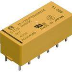
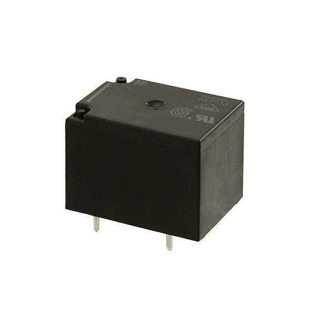
ICGOO电子元器件商城为您提供S4EB-L2-5V由Panasonic Corporation设计生产,在icgoo商城现货销售,并且可以通过原厂、代理商等渠道进行代购。 S4EB-L2-5V价格参考。Panasonic CorporationS4EB-L2-5V封装/规格:功率继电器,高于 2 A, 通用 继电器 4PST-NO(4 Form A) 5VDC 线圈 通孔。您可以下载S4EB-L2-5V参考资料、Datasheet数据手册功能说明书,资料中有S4EB-L2-5V 详细功能的应用电路图电压和使用方法及教程。
型号为 S4EB-L2-5V 的 Panasonic Electric Works 功率继电器,属于高电流继电器(额定电流高于2A),广泛应用于需要可靠电控开关的工业和自动化设备中。

该继电器的工作电压为5V DC,控制电路与负载电路之间具备良好的电气隔离,适用于多种控制场景。其主要应用场景包括:

1. 工业自动化控制系统:用于PLC(可编程逻辑控制器)输出端,控制电机、电磁阀、气缸等执行元件的启停。
2. 电源管理系统:在UPS(不间断电源)、配电柜中用于切换电源或负载,实现自动电源备份。
3. 暖通空调系统(HVAC):控制压缩机、风扇、加热元件等大功率部件的运行。
4. 安防与楼宇控制系统:用于门禁系统、照明控制、火灾报警系统中的自动开关控制。
5. 测试与测量设备:在自动化测试设备中作为开关元件,控制被测设备的通断电。

该继电器具有良好的耐久性和稳定性,适合在工业环境下长期运行,是实现自动化控制的重要元件。
| 参数 | 数值 |
| 产品目录 | |
| 描述 | RELAY GENERAL PURPOSE 4PST 4A 5V通用继电器 4PST PC BOARD |
| 产品分类 | |
| 品牌 | Panasonic Electric Works |
| 产品手册 | |
| 产品图片 |
|
| rohs | RoHS 合规性豁免无铅 / 符合限制有害物质指令(RoHS)规范要求 |
| 产品系列 | 通用继电器,Panasonic Industrial Devices S4EB-L2-5VS |
| mouser_ship_limit | 该产品可能需要其他文件才能进口到中国。 |
| 数据手册 | |
| 产品型号 | S4EB-L2-5V |
| 产品目录绘图 |
|
| 产品目录页面 | |
| 产品种类 | 通用继电器 |
| 关闭电压(最小值) | - |
| 其它名称 | 255-2835 |
| 其它有关文件 | |
| 功耗 | 192 mW |
| 包装 | 管件 |
| 商标 | Panasonic Industrial Devices |
| 安装类型 | 通孔 |
| 安装风格 | Through Hole |
| 导通电压(最大值) | 3.5 VDC |
| 封装 | Bulk |
| 工作时间 | 15ms |
| 工作温度 | -55°C ~ 65°C |
| 工厂包装数量 | 50 |
| 开关电压 | 250VAC,48VDC - 最小值 |
| 标准包装 | 50 |
| 特性 | 密封 - 琥珀色 |
| 相关产品 | /product-detail/zh/S-PS/255-1751-ND/570887 |
| 端子类型 | PC 引脚 |
| 端接类型 | Solder Pin |
| 线圈功率 | 192 mW |
| 线圈电压 | 5VDC |
| 线圈电流 | 38.5mA |
| 线圈电阻 | 130 欧姆 |
| 线圈端接 | Solder Pin |
| 线圈类型 | 锁存,双线圈 |
| 继电器类型 | 通用 |
| 触头外形 | 4PST(4 A 型) |
| 触头材料 | 银合金,无镉 |
| 触点形式 | 4PST (4 Form A) |
| 触点材料 | Silver Alloy |
| 触点端接 | Solder Terminal |
| 释放时间 | 15ms |
| 额定接触(电流) | 4A |


.jpg)


- 商务部:美国ITC正式对集成电路等产品启动337调查
- 曝三星4nm工艺存在良率问题 高通将骁龙8 Gen1或转产台积电
- 太阳诱电将投资9.5亿元在常州建新厂生产MLCC 预计2023年完工
- 英特尔发布欧洲新工厂建设计划 深化IDM 2.0 战略
- 台积电先进制程称霸业界 有大客户加持明年业绩稳了
- 达到5530亿美元!SIA预计今年全球半导体销售额将创下新高
- 英特尔拟将自动驾驶子公司Mobileye上市 估值或超500亿美元
- 三星加码芯片和SET,合并消费电子和移动部门,撤换高东真等 CEO
- 三星电子宣布重大人事变动 还合并消费电子和移动部门
- 海关总署:前11个月进口集成电路产品价值2.52万亿元 增长14.8%

PDF Datasheet 数据手册内容提取
2a2b/3a1b/4a 4A polarized S RELAYS power relays 2.Strong resistance to vibration and 7.Low thermal electromotive force shock High sensitivity (low power Use of 4G-BA technology realizes consumption) is realized by 4G-BA strong resistance to vibration and technology. Separation of the coil and shock. spring sections has resulted in a relay 3.High reliability and long life with extremely low levels of thermal Our application of 4G-BA technology, electromotive force (approx. 3 μV). along with almost perfectly complete 8.DIL terminal array twin contact, ensures minimal contact Deployed to fit a 2.54 mm .100 inch bounce and high reliability. grid, the terminals are presented in DIL RoHS compliant 4.Ability to provide wide-ranging arrays which match the printed circuit control board terminal patterns commonly in Use of 4G-BA technology with gold- international use. Protective construction: Sealed type clad silver alloy contacts in a twin 9.Relays that push the boundaries of contact structure enables control relay efficiency across a broad range from High-density S relays take you close to microcurrents of 100 μA 100 mV DC to the limits of relay efficiency. 4 A 250 V AC. 10. Sockets are available. 5.Latching types available With 4G-BA technology, as well as TYPICAL APPLICATIONS single side stable types, convenient 2 coil latching types for circuit memory Telecommunications equipment, data FEATURES applications are also available. processing equipment, facsimiles, alarm 1.Compact with high sensitivity 6.Wide variety of contact formations equipment, measuring equipment. The high-efficiency polarized available electromagnetic circuits of the 4-gap The compact size of the 4G-BA balanced armature and our exclusive mechanism enables the provision of spring alignment method achieves, many kinds of package, including with high-sensitivity in a small 2a2b, 3a1b, and 4a. These meet your package, a relay that can be directly needs across a broad range of controlled by a driver chip. applications. 4-GAP BALANCED ARMATURE MECHANISM 1. Armature mechanism has excellent 2. High sensitivity and reliability Panasonic Corporation, provides a highly resistance to vibration and shock provided by 4-gap balanced armature efficient polarized magnetic circuit The armature structure enables free mechanism structure that is both highly sensitive and rotation around the armature center of As a (polarized) balanced armature, the has a small form factor. Moreover, gravity. Because the mass is maintained S relay armature itself has two suitability for provision with many types of in balance at the fulcrum of the axis of permanent magnets. Presenting four contact array and other advantages rotation, large rotational forces do not interfaces, the armature has a 4-gap promise to make it possible to provide occur even if acceleration is applied structure. As a result, the rotational axis many of the various characteristics that along any vector. The mechanism has at either end of the armature is are coming to be demanded of relays. proven to have excellent resistance to symmetrical and, in an energized into a vibration and shock. All our S relays are polarized state, the twin magnetic based on this balanced armature armature interfaces are subject to mechanism, which is able to further repulsion on one side and attraction on provide many other characteristics. the other. This mechanism, exclusive to –1– ASCTB207E 201701-T
S HOW IT WORKS (single side stable type) 1) When current is passed through the 3) At this time, opening and closing coil, the yoke becomes magnetic and operates owing to the action of the Repulsion Permanent magnet polarized. simultaneously moulded balanced Residual plate NS N Attraction 2) At either pole of the armature, armature mechanism, so that when the Attraction NS repulsion on one side and attraction on force of the contact breaker spring closes S Axis the other side is caused by the interaction the contact on one side, on the other Repulsion of the poles and the permanent magnets side, the balanced armature opens the of the armature. contact (2a2b). ORDERING INFORMATION S EB Contact arrangement 2: 2 Form A 2 Form B 3: 3 Form A 1 Form B 4: 4 Form A Operating function Nil:Single side stable L: 1 coil latching* L2:2 coil latching Nominal coil voltage (DC) 3, 5, 6, 12, 24, 48 V Note: *1 coil latching type are manufactured by lot upon receipt of order. TYPES Single side stable 2 coil latching Contact arrangement Nominal coil voltage Part No. Part No. 3V DC S2EB-3V S2EB-L2-3V 5V DC S2EB-5V S2EB-L2-5V 6V DC S2EB-6V S2EB-L2-6V 2 Form A 2 Form B 12V DC S2EB-12V S2EB-L2-12V 24V DC S2EB-24V S2EB-L2-24V 48V DC S2EB-48V S2EB-L2-48V 3V DC S3EB-3V S3EB-L2-3V 5V DC S3EB-5V S3EB-L2-5V 6V DC S3EB-6V S3EB-L2-6V 3 Form A 1 Form B 12V DC S3EB-12V S3EB-L2-12V 24V DC S3EB-24V S3EB-L2-24V 48V DC S3EB-48V S3EB-L2-48V 3V DC S4EB-3V S4EB-L2-3V 5V DC S4EB-5V S4EB-L2-5V 6V DC S4EB-6V S4EB-L2-6V 4 Form A 12V DC S4EB-12V S4EB-L2-12V 24V DC S4EB-24V S4EB-L2-24V 48V DC S4EB-48V S4EB-L2-48V Standard packing: Carton: 50 pcs.; Case: 500 pcs. * Sockets available. RATING 1. Coil data 1) Single side stable Nominal operating Coil resistance Max. applied Type Novmoilntaagl ecoil P(aict k2-0u°pC v o6l8ta°Fge) D(raotp 2-0o°uCt v6o8lt°aFg)e c(autr r2e0n°tC [± 6180°%F)] (at 2[±01°C0% 6]8 °F) Nominpaol wopeerrating (at 4v0o°lCta 1g0e4 °F) 3V DC 66.7mA 45Ω 200mW 5.5V DC 5V DC 38.5mA 130Ω 192mW 9.0V DC 6V DC 70%V or less of 10%V or more of 33.3mA 180Ω 200mW 11.0V DC Standard nominal voltage nominal voltage 12V DC (Initial) (Initial) 16.7mA 720Ω 200mW 22.0V DC 24V DC 8.4mA 2,850Ω 202mW 44.0V DC 48V DC 5.6mA 8,500Ω 271mW 75.0V DC –2– ASCTB207E 201701-T
S 2) 2 coil latching Type Novmoilntaagl ecoil (aSt e2t0 v°Col t6a8g°eF ) (Raet s2e0t° Cvo 6lt8a°gFe) Noc(amutr ir2ne0an°lt C o[±p 61e80r°a%Fti)n] g Coil (raets 2is0t°aCn c6e8 °[±F1)0%] No(amt i2np0ao°l wCope 6er8 r°aFti)ng (aMt 4av0xo.° lCatap 1gp0eli4 e°dF ) Set coil Reset coil Set coil Reset coil Set coil Reset coil 3V DC 66.7mA 66.7mA 45Ω 45Ω 200mW 200mW 5.5V DC 5V DC 38.5mA 38.5mA 130Ω 130Ω 192mW 192mW 9.0V DC 6V DC 70%V or less of 70%V or less of 33.7mA 33.7mA 180Ω 180Ω 200mW 200mW 11.0V DC Standard nominal voltage nominal voltage 12V DC (Initial) (Initial) 16.7mA 16.7mA 720Ω 720Ω 200mW 200mW 22.0V DC 24V DC 8.4mA 8.4mA 2,850Ω 2,850Ω 202mW 202mW 44.0V DC 48V DC 7.4mA 7.4mA 6,500Ω 6,500Ω 355mW 355mW 65.0V DC 2. Specifications Characteristics Item Specifications Arrangement 2 Form A 2 Form B, 3 Form A 1 Form B, 4 Form A Contact resistance (Initial) Max. 50 mΩ (By voltage drop 6 V DC 1A) Electrostatic capacitance (initial) Approx. 3pF Contact Contact material Au clad Ag alloy (Cd free) Thermal electromotive force (at nominal coil voltage) Approx. 3μV (initial) Nominal switching capacity (resistive load) 4 A 250 V AC, 3 A 30 V DC Max. switching power (resistive load) 1,000 VA, 90 W Rating Max. switching voltage 250 V AC, 48 V DC (30 to 48 V DC at less than 0.5 A) Max. switching current 4 A (AC), 3 A (DC) Min. switching capacity (Reference value)*1 100μA 100 m V DC Min. 10,000MΩ (at 500V DC) Insulation resistance (Initial) Measurement at same location as “Breakdown voltage” section. Between open contacts 750 Vrms for 1min. (Detection current: 10mA.) Breakdown voltage Electrical (Initial) Between contact sets 1,000 Vrms for 1min. (Detection current: 10mA.) characteristics Between contact and coil 1,500 Vrms for 1min. (Detection current: 10mA.) Operate time [Set time] (at 20°C 68°F) Max. 15 ms [15 ms] (Nominal coil voltage applied to the coil, excluding contact bounce time.) Release time [Reset time] (at 20°C 68°F) Max. 10 ms [15 ms] (Nominal coil voltage applied to the coil, excluding contact bounce time.) (without diode) Functional Min. 490 m/s2 (Half-wave pulse of sine wave: 11 ms; detection time: 10μs.) Shock resistance Mechanical Destructive Min. 980 m/s2 (Half-wave pulse of sine wave: 6 ms.) characteristics Functional 10 to 55 Hz at double amplitude of 3 mm (Detection time: 10μs.) Vibration resistance Destructive 10 to 55 Hz at double amplitude of 4 mm Expected life Mechanical Min. 108 (at 50 cps) Ambient temperature: –55°C to +65°C –67°F to +149°F Conditions Conditions for operation, transport and storage*2 Humidity: 5 to 85% R.H. (Not freezing and condensing at low temperature) Unit weight Approx. 8 g .28 oz Notes:*1.This value can change due to the switching frequency, environmental conditions, and desired reliability level, therefore it is recommended to check this with the actual load. *2.The upper limit of the ambient temperature is the maximum temperature that can satisfy the coil temperature rise value. Refer to Usage, transport and storage conditions in NOTES. 3. Electrical life Condition: Resistive load, at 20 times/min. Types Switching capacity No. of operations 4A 250 V DC Min. 1×10⁵ 2 Form A 2Form B, 3 Form A 1 Form B, 4 Form A 3A 30V DC Min. 2×10⁵ –3– ASCTB207E 201701-T
S REFERENCE DATA 1. Maximum switching power 2. Life curve 3. Contact reliability Condition: 1V DC, 1mA Detection level 10 Ω Tasted Sample: S4EB-24V, 10pcs 1,000 1,000 99.9 DC resistive load AC resistive load 9995..00 500 V 70.0 ntact voltage, 100 4×Life, 10 10500 1355000....0000 o C 10 30 2.0 m = 1.6 125 V AC 1.0 μ: 79 million time (cosϕ = 1.0) σ: 51 million time 10 250 V AC 0.5 95% reliability limit: (cosϕ = 1.0) 0.2 14.6 million times (weibul probability paper) 0.1 0.1 1 10 0 1 2 3 4 5 1.0 10.0 Contact current, A Contact current, A No. of operations, ×107 4.-(1) Coil temperature rise 4.-(2) Coil temperature rise 5. Operate and release time Tested Sample: S4EB-24V, 4 Form A Tested Sample: S4EB-24V, 4 Form A (Single side stable type) Tested Sample: S4EB-24V, 10pcs 100 100 20 90 90 18 °Temperature rise, C 876543000000 40AA °Temperature rise, C 876543000000 Cpoowil eorp, e0r.a2t iWng Operate/release time, ms 1111642086 Release timOep (ewraitthe dtiimodee)MMianx.. Max. 20 20 4Max. Min. 10 10 2Min. Release time 0 0 0 0.2 0.4 0.6 0.8 1.0 1.2 1 2 3 4 5 6 80 100 120 140 Coil operating power, W Contact current, A Coil applied voltage, %V 6. Influence of adjacent mounting Note:When installing an S-relay near another, and there is no effect from an external magnetic field, be sure to leave at least 10 mm .394 inch between relays in order to achieve the performance (1) (2) (3) (1) & (3) relays listed in the catalog. are energized % % ge, +30Single side stable ge, +302 coil latching n n a a of ch Drop-out voltage of ch ate 0 ate 0 R Pick-up voltage R Pick-up voltage –30 –30 5 10 5 10 Inter-relay distance, mm Inter-relay distance, mm 7. Effect from an external magnetic field Rate of change, % +300Single side stable DroφpP-iocukt- uvpo lvtaoglteage Rate of change, % +300Single side staφble DProicpk--ouupt vvoollttaaggee –30 –30 50 100 50 100 % 2 coil latching G % 2 coil latching G Rate of change, +300 Pick-up voltage Rate of change, +300 Pick-up voltage –30 –30 50 100 50 100 G G –4– ASCTB207E 201701-T
S DIMENSIONS (mm inch) The CAD data of the products with a CAD Data mark can be downloaded from: http://industrial.panasonic.com/ac/e/ CAD Data External dimensions Schematic (Bottom view) Single side stable 2 coil latching 28±0.5 12 1.102±0.02 .472 (Deenergized position) (Reset condition) 1 10±0.5 1 2 3 4 5 6 1 2 3 4 5 6 .039 .394±0.02 + + + 4 0.5 2a2b .157 0.4 .020 - - - 1.0 .016 1.4 .039 7.62 .055 .300 12 11 10 9 8 7 12 11 10 9 8 7 3 .118 1 2 3 4 5 6 7.3.6020.41722 12 11 10 9 8 7 1 2 3 4 5 6 1 2 3 4 5 6 .002.50 .52.0008 3a1b + + + - - - General tolerance: ±0.3 ±.012 12 11 10 9 8 7 12 11 10 9 8 7 PC board pattern (Copper-side view) 1 2 3 4 5 6 1 2 3 4 5 6 2.54 + + + .100 4a - - - 12-1.3 dia. 12 11 10 9 8 7 12 11 10 9 8 7 .047-.051 dia. 2.54 .100 Tolerance: ±0.1 ±.004 SAFETY STANDARDS UL/C-UL (Recognized) CSA (Certified) File No. Contact rating File No. Contact rating 4A 250V AC 4A 250V AC 3A 30V DC 3A 30V DC E43028 LR26550 1/20HP 250V AC (FLA0.75A) 1/20HP 250V AC 1/20HP 125V AC (FLA1.5A) 1/20HP 125V AC NOTES 1. For cautions for use, please read 3. Please note that when this relay “GENERAL APPLICATION (2 Form A 2 Form B type, 3 Form A GUIDELINES”. 1 Form B type) operates and releases, 2. Based on regulations regarding contacts a and b may go ON at the insulation distance, there is a same time. restriction on same-channel load connections between terminals No. 2, 3 and 4, 5, as well as between No. 8, 9 and 10, 11. See the figure below for an example. 2 3 4 5 23 45 11 10 9 8 11 10 98 • Between 2, 3 and 4, 5: • Between 2, 3 and 4, 5: different channels, therefore not possible same channels, therefore possible • Between 10, 11 and 8, 9: • Between 10, 11 and 8, 9: different channels, therefore not possible same channels, therefore possible No good Good –5– ASCTB207E 201701-T
S RELAYS ACCESSORIES PC BOARD SOCKET DIMENSIONS (mm inch) The CAD data of the products with a CAD Data mark can be downloaded from: http://industrial.panasonic.com/ac/e/ CAD Data External dimensions PC board pattern (Copper-side view) 12.4±0.6 .488±.024 7.6 .299 5.085.085.085.085.08 12-1.6 dia. hole.200.200.200.200.200 12-.063 dia. hole 18.3±0.6 .72.004±17..0±22.±0401.23 .61150.5±±.00.264 Tolerance: ±0.1 ±.004 0.4±0.1 .016±.004 .149.18±5.±001.23 .23502.00.48±±±.0001..362 .370.602±±.001.32 .133.44±±.00.132 1.5±0.3 1.276±.024 1.5±0.3 Terminal width: 1.3.051 .059±.012 .059±.012 Terminal thickness: 1.2.047 General tolerance: ±0.3 ±.012 RoHS compliant TYPES Product name Part No. S Relays PC board socket S-PS SPECIFICATIONS 4 A Maximum continuous current Note: Don’t insert or remove relays while in the energized condition. Breakdown voltage 1,500 Vrms between terminals Insulation resistance More than 100 MΩ between terminals at 500 V DC Mega Heat resistance 150 ±3°C (302 ±5.4°F) for 1 hour. NOTES Inserting and removing method Inserting method: Insert the relay as Rib shown in Fig. 1 unit the rib of the relay snaps into the clip of the socket. Fig. 1 Removing method: (1) Remove the relay straight from the socket holding the shaded portion of the Fig. 2 relay as shown in Fig. 2. (2) When sockets are mounted in close proximity, use a slotted screw driver as shown in Fig. 3. Fig. 3 –1– ASCTB262E 201701-T
None
Mouser Electronics Authorized Distributor Click to View Pricing, Inventory, Delivery & Lifecycle Information: P anasonic: S2EB-12V S-PS S2EB-L2-5V S2EB-5V S4EB-5V S2EB-L2-12V S4EB-12V S2EB-L2-24V S2EB-24V S4EB-24V S2EB-L2-6V S2EB-6V S2EB-48V S2EB-3V S2EB-L2-3V S2EB-L2-48V S3EB-12V S3EB-24V S3EB-48V S3EB- L2-12V S3EB-L2-24V S3EB-L2-5V S4EB-3V S4EB-48V S4EB-6V S4EB-L2-12V S4EB-L2-24V S4EB-L2-3V S4EB-L2-48V S4EB-L2-5V S4EB-L2-6V S2EB-L-12V S2EB-L-24V S2EB-L-3V S2EB-L-5V S3EB-9V S3EB-L-12V S3EB-L2-DC48V S4EB-9V S4EB-L-12V S4EB-L-3V