ICGOO在线商城 > 继电器 > 功率继电器,高于 2 A > SF4D-DC24V
 Datasheet下载
- 型号: SF4D-DC24V
- 制造商: Panasonic Corporation
- 库位|库存: xxxx|xxxx
- 要求:
| 数量阶梯 | 香港交货 | 国内含税 |
| +xxxx | $xxxx | ¥xxxx |
查看当月历史价格
查看今年历史价格
SF4D-DC24V产品简介:
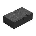
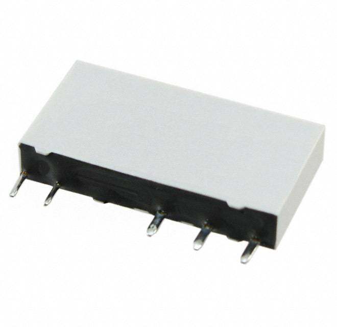
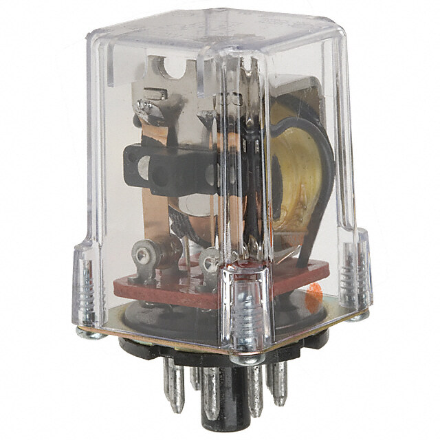
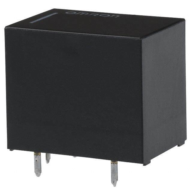
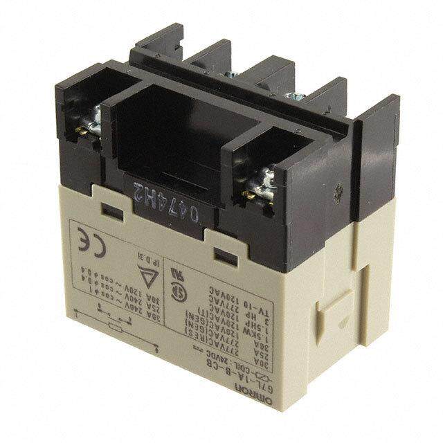
ICGOO电子元器件商城为您提供SF4D-DC24V由Panasonic Corporation设计生产,在icgoo商城现货销售,并且可以通过原厂、代理商等渠道进行代购。 SF4D-DC24V价格参考。Panasonic CorporationSF4D-DC24V封装/规格:功率继电器,高于 2 A, 安全 继电器 8PST-4NO/4NC(4 Form A,4 Form B) 24VDC 线圈 通孔。您可以下载SF4D-DC24V参考资料、Datasheet数据手册功能说明书,资料中有SF4D-DC24V 详细功能的应用电路图电压和使用方法及教程。
Panasonic Electric Works的SF4D-DC24V是一款功率继电器,额定电流高于2A,广泛应用于工业自动化与电力控制领域。其典型应用场景包括:

1. 工业设备控制:用于机床、包装机械、输送带系统等设备中,控制电机、电磁阀、加热器等大功率负载的通断。

2. 楼宇自动化系统:在暖通空调(HVAC)系统中控制压缩机、风机和泵的启停,或用于智能照明系统的分区控制。

3. 能源管理系统:在太阳能逆变器、储能系统或智能电网中,作为高可靠性开关元件实现负载切换和电能分配。

4. 安防与消防系统:用于火灾报警控制器、门禁系统或监控设备中,驱动警报装置、排烟风机等关键部件。

5. 交通运输设备:如自动售货机、电梯控制系统及轨道交通设备中,满足频繁操作与高稳定性的需求。

该继电器采用直流24V线圈驱动,具备良好的抗干扰能力和长寿命设计,适合在复杂电磁环境和较高工作频率的场合使用。
| 参数 | 数值 |
| 产品目录 | |
| 描述 | RELAY SAFETY 8PST 6A 24V通用继电器 6A 24V 2FORMA/2FORMB PCB |
| 产品分类 | |
| 品牌 | Panasonic Electric Works |
| 产品手册 | http://panasonic-denko.co.jp/ac/e_download/control/relay/safety/catalog/mech_eng_sfw.pdf?via=ok |
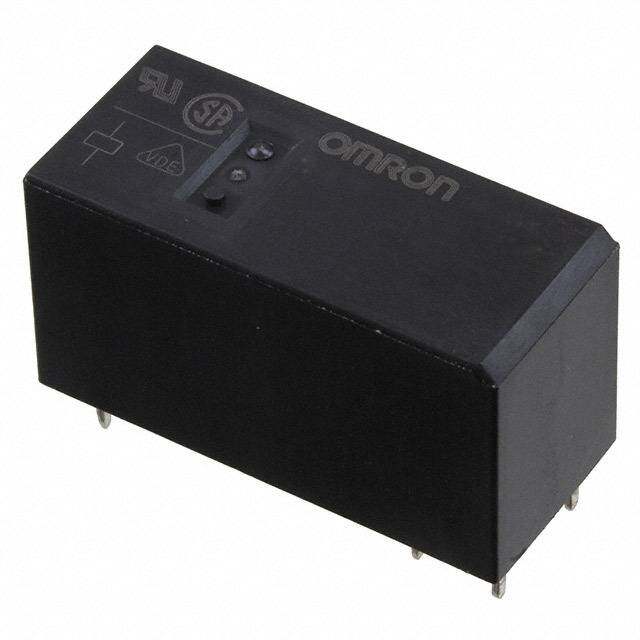
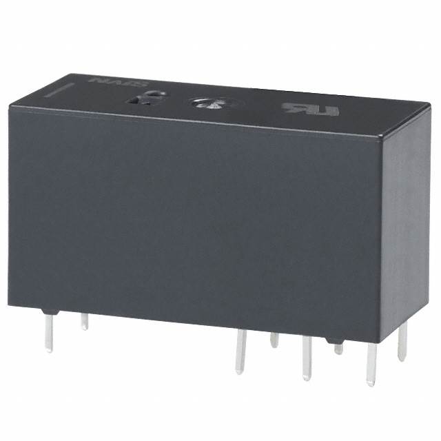
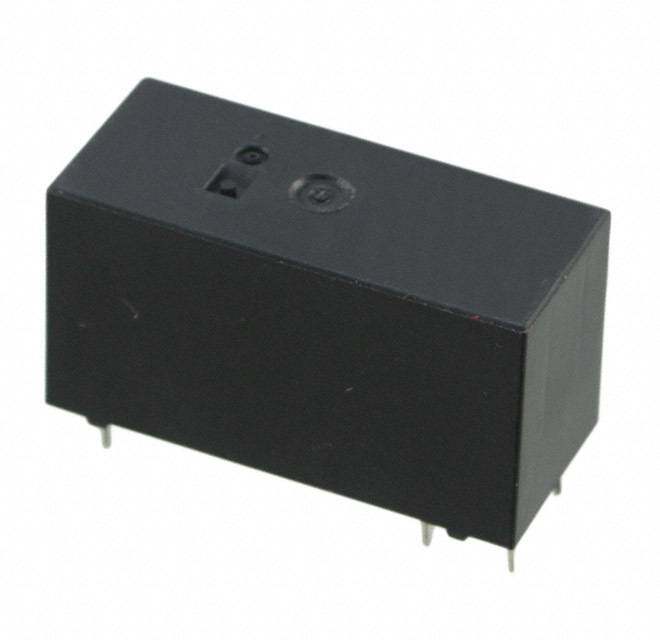
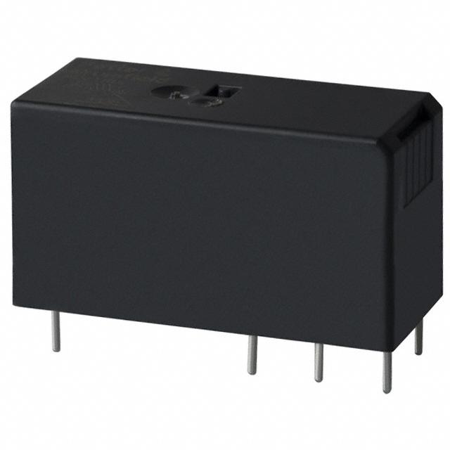
| 产品图片 |
|
| rohs | RoHS 合规性豁免无铅 / 符合限制有害物质指令(RoHS)规范要求 |
| 产品系列 | 通用继电器,Panasonic Industrial Devices SF4D-DC24VSF4D |
| mouser_ship_limit | 该产品可能需要其他文件才能进口到中国。 |
| 数据手册 | |
| 产品型号 | SF4D-DC24V |
| 产品 | Power Relays |
| 产品目录绘图 |
|
| 产品目录页面 | |
| 产品种类 | Power Relays |
| 关闭电压(最小值) | 3.6 VDC |
| 其它名称 | 255-1441 |
| 其它有关文件 | |
| 功耗 | 500 mW |
| 包装 | 散装 |
| 商标 | Panasonic Industrial Devices |
| 安装类型 | 通孔 |
| 安装风格 | Through Hole |
| 导通电压(最大值) | 14.4 VDC |
| 封装 | Bulk |
| 工作时间 | 18ms |
| 工作温度 | -40°C ~ 70°C |
| 工厂包装数量 | 20 |
| 开关电压 | 440VAC,30VDC - 最小值 |
| 标准包装 | 20 |
| 特性 | - |
| 端子类型 | PC 引脚 |
| 端接类型 | Solder Pin |
| 类型 | Polarized Power Relay |
| 线圈功率 | 500 mW |
| 线圈电压 | 24VDC |
| 线圈电流 | 20.8mA |
| 线圈电阻 | 1.15 千欧 |
| 线圈端接 | Solder Pin |
| 线圈类型 | 无锁存 |
| 继电器类型 | 安全 |
| 触头外形 | 8PST(4 A 型,4 B 型) |
| 触头材料 | 银锡氧化物(AgSnO) |
| 触点形式 | 4 Form A (4PST-NO), 4 Form B (4PST-NC) |
| 触点材料 | Silver Alloy |
| 触点端接 | Pin |
| 释放时间 | 7ms |
| 额定接触(电流) | 6A |


.jpg)

.jpg)

- 商务部:美国ITC正式对集成电路等产品启动337调查
- 曝三星4nm工艺存在良率问题 高通将骁龙8 Gen1或转产台积电
- 太阳诱电将投资9.5亿元在常州建新厂生产MLCC 预计2023年完工
- 英特尔发布欧洲新工厂建设计划 深化IDM 2.0 战略
- 台积电先进制程称霸业界 有大客户加持明年业绩稳了
- 达到5530亿美元!SIA预计今年全球半导体销售额将创下新高
- 英特尔拟将自动驾驶子公司Mobileye上市 估值或超500亿美元
- 三星加码芯片和SET,合并消费电子和移动部门,撤换高东真等 CEO
- 三星电子宣布重大人事变动 还合并消费电子和移动部门
- 海关总署:前11个月进口集成电路产品价值2.52万亿元 增长14.8%


PDF Datasheet 数据手册内容提取
SF RELAYS Flat type safety relays (double contact) Double contact type FEATURES 1. High contact reliability 5. High breakdown voltage High contact reliability is achieved High breakdown voltage 2,500 Vrms through the use of a double contact. between contacts and coil. 2. Forced operation contacts 6. High sensitivity N.O. and N.C. side contacts are Realizes thin shape and high sensitivity connected through a card so that one (500 mW nominal operating power) by interacts with the other in movement. In utilizing high-efficiency polarized 2 Form A 2 Form B case of a contact welding, the other magnetic circuit with 4-gap balanced keeps a min. 0.5mm .020inch contact armature. gap. 7. Complies with safety standards 3. Independent operation contacts Standard products are UL, CSA, TÜV (4 Form A 4 Form B) and SEV certified. Conform to European There are 4 points of forced operation standards. TÜV certified. Complies with contacts. SUVA European standard. Each pair of contacts is free from the main armature and is independent from TYPICAL APPLICATIONS each other. So if a N.O. pair of contacts 4 Form A 4 Form B are welded, the other 3 N.O. contacts are 1. Industrial equipment such as not effected (operate properly) That presses and machine tools enables to plan a circuit to detect welding 2. Elevators and other kinds of or go back to the beginning condition. hoisting mechanisms, conveyor 4. Separated chamber structure equipment. N.O. and N.C. side contacts are put in each own space surrounded with a card and a body-separater. That prevents short circuit between contacts, which is caused by their springs welding or RoHS compliant damaged. ORDERING INFORMATION SF D Contact arrangement 2: 2 Form A 2 Form B 4: 4 Form A 4 Form B Nominal coil voltage DC 5, 12, 24, 48, 60V Note: Certified by UL, CSA, TÜV and SEV TYPES Contact arrangement Nominal coil voltage Part No. 5V DC SF2D-DC5V 12V DC SF2D-DC12V 2 Form A 2 Form B 24V DC SF2D-DC24V 48V DC SF2D-DC48V 60V DC SF2D-DC60V 5V DC SF4D-DC5V 12V DC SF4D-DC12V 4 Form A 4 Form B 24V DC SF4D-DC24V 48V DC SF4D-DC48V 60V DC SF4D-DC60V Standard packing: Carton: 20 pcs.; Case: 200 pcs. –1– ASCTB120E 201408-T
SF Double contact type RATING 1. Coil data Nominal coil current Coil resistance Nominal operating Max. applied arrCanognetamcet nt Novmoilntaagl ecoil P(aict k2-0u°pC v o6l8ta°Fge) D(raotp 2-0o°uCt v6o8lt°aFg)e (at 2[±01°C0% 6]8 °F) (at 2[±01°C0% 6]8 °F) (at 2p0o°wCe 6r8 °F) (at 2v0o°ltCa g6e8 °F) 5V DC 100mA 50Ω 12V DC 75%V or less of 10%V or more of 41.7mA 288Ω 2 Form A 2 Form B 24V DC nominal voltage nominal voltage 20.8mA 1,152Ω 500mW 48V DC (Initial) (Initial) 10.4mA 4,608Ω 60V DC 8.3mA 7,200Ω 120%V of 5V DC 100mA 50Ω nominal voltage 12V DC 75%V or less of 15%V or more of 41.7mA 288Ω 4 Form A 4 Form B 24V DC nominal voltage nominal voltage 20.8mA 1,152Ω 500mW 48V DC (Initial) (Initial) 10.4mA 4,608Ω 60V DC 8.3mA 7,200Ω 2. Specifications Characteristics Item Specifications Arrangement 2 Form A 2 Form B 4 Form A 4 Form B Contact Contact resistance (Initial) Max. 30 mΩ (By voltage drop 6 V DC 1A) Contact material Au-flashed AgSnO2 type Nominal switching capacity (resistive load) 6A 250V AC, 6A 30V DC Max. switching power (resistive load) 1,500VA 180W Max. switching voltage 440V AC, 30V DC Rating Max. switching current 6A Nominal operating power 500mW Min. switching capacity (Reference value)*1 100mA 5V DC Insulation resistance (Initial) Min. 1,000MΩ (at 500V DC) Measurement at same location as “Breakdown voltage” section. Between open contacts 1,300 Vrms for 1min. (Detection current: 10mA) Breakdown voltage Between contact sets 2,500 Vrms for 1min. (Detection current: 10mA) (Initial) Between contact and coil 2,500 Vrms for 1min. (Detection current: 10mA) Electrical characteristics Temperature rise (coil) (at 20° 68°F) Max. 45°C 113°F (By resistive method, nominal voltage applied to the coil; contact carrying current: 6A) Operate time Max. 30ms (Nominal voltage applied to the coil, excluding contact bounce time.) Max. 15ms (Nominal voltage applied to the coil, excluding contact bounce time.) Release time (without diode) Functional Min. 294 m/s2 (Half-wave pulse of sine wave: 11 ms; detection time: 10μs) Shock resistance Mechanical Destructive Min. 980 m/s2 (Half-wave pulse of sine wave: 6 ms) characteristics Functional 10 to 55 Hz at double amplitude of 2 mm (Detection time: 10μs) Vibration resistance Destructive 10 to 55 Hz at double amplitude of 2 mm Mechanical Min. 107 (at 180 times/min.) Expected life Electrical Min. 105 (at 20 times/min.) Ambient temperature: –40°C to +70°C –40°F to +158°F Conditions for operation, transport and storage*2 Conditions Humidity: 5 to 85% R.H. (Not freezing and condensing at low temperature) Max. Operating speed 180 times/min. Unit weight Approx. 38g 1.34oz Approx. 47g 1.66oz Notes:*1.This value can change due to the switching frequency, environmental conditions and desired reliability level, therefore it is recommended to check this with the actual load. *2.The upper limit of the ambient temperature is the maximum temperature that can satisfy the coil temperature rise value. Refer to Usage, transport and storage conditions in NOTES. –2– ASCTB120E 201408-T
SF Double contact type REFERENCE DATA 1. Operate/release time (without diode) 2. Temperature rise 3. Ambient temperature characteristics Tested sample: SF2D-DC24V (2 Form A 2 Form B) Tested sample: SF4D-DC24V (4 Form A 4 Form B) Tested sample: SF4D-DC24V (4 Form A 4 Form B) Quantity: n = 20 Quantity: n = 6 Quantity: n = 6 Coil applied voltage: 100%V, 120%V Contact carry current: 6A 50 30 % 100 me, ms40 °e, C25 Inside the coil Rate ofchange, 50 Operate/release ti2300 Operate time Max. Temperature ris112050 Contact -40 -20 0 20 40Drop6AtPe-0omimcubkpt- ie8evur0onpalt ttvauogrleeta, g°Ce 10 Release time MMxainx.. 5 -50 x Min. 0 0 -100 70 80 90 100 110 120 130 100 110 120 Coil applied voltage, %V Coil applied voltage, %V DIMENSIONS (mm inch) The CAD data of the products with a CAD Data mark can be downloaded from: http://industrial.panasonic.com/ac/e/ 1. 2 Form A 2 Form B External dimensions Schematic (Bottom view) CAD Data 5 6 7 8 1 16±0.5 .630±.020 2 0.5 9 10 11 12 .020 .013.09 .52.0008 .1520.07 .1520.07 1.520.70 1.0.039 .31.108±0±..0520 PC board pattern (Bottom view) 53.3±0.5 0.30 2.098±.020 .00.1498 2.1.5040 1100-.-015.45 ddiiaa.. hhoolleess .012 5 6 7 8 2.54 25.0 .100 .984 1 7.62 12.7 .300 .500 2 9 10 11 12 General tolerance: ±0.3 ±.012 Tolerance: ±0.1 ±.004 2. 4 Form A 4 Form B External dimensions Schematic (Bottom view) CAD Data 13 14 15 16 .61360±±0.0.520 1 5 6 7 8 0.5 9 10 11 12 .020 2 .10.309 5.2.0080 1.520.70 1.520.70 1.520.70 1.0.039 3.1.018±0±..0520 17 18 19 20 53.3±0.5 0.48 2.098±.020 .019 PC board pattern (Bottom view) 1.23939±±0..0520 0.0.3102 1153 164 175 186 7.3.6020 2.1.5040 1188-.-015.45 ddiiaa.. hhoolleess 7.62 0.48 12.7 2.54 .300 .019 .500 .100 2 9 10 11 12 7.62 17 18 19 20 .300 General tolerance: ±0.3 ±.012 Tolerance: ±0.1 ±.004 –3– ASCTB120E 201408-T
SF Double contact type SAFETY STANDARDS UL/C-UL (Recognized) TÜV (Certified) SEV File No. Contact rating File No. Rating File No. Contact rating E120782* 6A 250V AC 968 EZ 116.03/10 (SF2D) 3A 24V DC 12.0520 6A 24V DC 6A 24V DC 968 EZ 116.02/09 (SF4D) 6A 250V AC 6A 250V AC *CSA standard: Certified by C-UL SAFETY STRUCTURE OF SF RELAYS This SF relay design ensures that (unforeseen externally caused circuit or scenario, relay breakdown (coil rupture, subsequent operations shut down and device breakdowns, end of life incidents, faulty operation, faulty return, and fatigue can automatically return to a safe state and noise, surge, and environmental and breakage of the operating spring and when the SF relay suffers overloading influences) owing to contact welding, return spring), and even in the event of and other circuit abnormalities spring fusion or, in the worst-case end of life. Structure Operation Min. 0.5 mm.020 inch Even when one contact is welded closed, the other maintains a gap of greater than 0.5 mm .020 inch. Contact a 1. Forced operation method (2 Form A 2 Form B, Card In the diagram on the left, the lower contact “b” have welded but the upper contact “a” maintain at a gap of 4 Form A 4 Form B types) Contact b greater than 0.5 mm .020 inch. Subsequent contact movement is suspended and the Weld weld can be detected The two contacts “a” and “b” are coupled with the same card. The operation of each contact is regulated by the movement of the other contact. External NO contact weld Return Enables design of safety circuits that allow weld detection and return at an early stage. 2. Independent operation method As shown at the top right of the diagram on the left, if (4 Form A 4 Form B type) the external N.O. contact welds, a 0.5 mm .020 inch Return Return gap is maintained. Each of the other contacts returns to N.O. because the coil is no longer energized. None of four contacts are held in position by the armature. Even though one of the external N.O. contacts has welded, the other three contacts have returned owing to the de-energizing of the coil. Case separator 1 Card Contact a Prevents shorting and fusing of springs and spring failure owing to short-circuit current. 3. Separate chamber method Body (2 Form A 2 Form B, 2 separator As shown on the diagram on the left, even if the 4 Form A 4 Form B types) Contact b operating springs numbered 1 and 2 there is no shorting between “a” and “b” contacts. In independent chambers, the contacts “a” and “b” are kept apart by a body/ case separator or by the card itself. Independent COM enables differing pole circuit 4. 2 Form A 2 Form B contact Structure with independent COM contact of 2 Form A 2 Form B and configurations. This makes it possible to design 4 Form A 4 Form B contact 4 Form A 4 Form B contacts. various kinds of control circuits and safety circuits. –4– ASCTB120E 201408-T
SF Double contact type THE OPERATION OF SF RELAYS (when contacts are welded) SF relays work to maintain a normal operating state even when the contact welding occur by overloading or short-circuit currents. It is easy to make weld detection circuits and safety circuits in the design to ensure safety even if contacts weld. 1) 2 Form A 2 Form B type Form “b” Contact Weld If the form “b” contact (No. 1 and 3) welds, the armature becomes non-operational, the contact gaps at the three form “a” contacts are maintained at greater than 0.5 mm .020 inch. Reliable isolation is thus ensured. No.4 No.1 No.4 No.1 Example: If the No. 1 contact welds Each of the three form “a” contacts (No. 2 and 4) maintain a gap of greater than 0.5 mm .020 inch. No.3 No.2 No.3 No.2 Non-energized Energized (when No. 1 contact is welded) Form “a” Contact Weld When the form “a” contacts (No. 2 or 4) weld, the armature remains in a non-returned state and the contact gap at the two form “b” contact is maintained at greater than 0.5 mm .020 inch. Reliable isolation is thus ensured. No.4 No.1 No.4 No.1 Example: If the No. 2 contact welds. The two form “b” contact (No. 1 or 3) maintains a gap of greater than 0.5 mm .020 inch. No.3 No.2 No.3 No.2 Energized Non-energized (when No. 2 contact is welded) Contact Operation Table The table below shows the state of the other contacts when the current through the welded form “a” contact is 0 V and the rated voltage is applied through the form “b” contact. No.4 No.1 State of other contacts 1 2 3 4 No.3 No.2 1 >0.5 >0.5 >0.5: contact gap is kept at tWeremldineadl 2 >0.5 >0.5 E m p t ym cine.l l0s:. 5e imthmer .c0l2o0s eindc ohr open No. 3 >0.5 >0.5 Contact No. No.1 No.2 No.3 No.4 4 >0.5 >0.5 Terminal No. 11–12 7–8 5–6 9–10 *Contact gaps are shown at the initial state. If the contacts change state owing to loading/breaking it is necessary to check the actual loading. –5– ASCTB120E 201408-T
SF Double contact type 2) 4 Form A 4 Form B type Internal Contacts Weld When internal contacts (No. 2, No. 3, No. 6 or No. 7) are welded, the armature becomes non-operational and the four form “a” contact gaps are maintained at 0.5 mm .020inch or greater. Reliable cut-off is thus ensured. No.8 No.1 No.8 No.1 No.7 No.2 No.7 No.2 Example: If the No. 2 contact welds. Each of the four form “a” contacts (No. 1, 3, 5, and 7) No.6 No.3 No.6 No.3 maintains a gap of greater than 0.5 mm .020 inch. No.5 No.4 No.5 No.4 Non-energized Energized (when no. 2 contact is welded) External Contacts Weld When external contacts (No. 1, No. 4, No. 5 or No. 8) are welded, gaps of 0.5 mm .020inch and greater are maintained between adjacent contacts and other contacts operate normally by the coil being non-energized. No.8 No.1 No.8 No.1 Example 1: If the No. 1 contact welds. No.7 No.2 No.7 No.2 The adjacent No. 2 contact maintains a gap of greater than 0.5 mm .020 inch. The other contacts, because the coil is not energized, return to their normal return state; each of form “a” contacts (No. 3, 5, and 7) No.6 No.3 No.6 No.3 maintains a contact gap of greater than 0.5 mm No.5 No.4 No.5 No.4 .020 inch; each of the form “b” contacts (No. 4, 6, and 8) return to a closed state. Energized Non-energized (when no. 1 contact is welded) Example 2: Weld If external connections are made in series. Even if one of the contacts welds, the other contacts Energized operate independently and the contact gaps are Contact gap maintained at greater than 0.5 mm .020 inch. min 0.5 mm.020 inch Non-energized Contact Operation Table The table below shows the state of the other contacts when the current through the welded form “a” contact is 0 V and the rated voltage is applied through the No.8 No.1 form “b” contact. No.7 No.2 Contact No. State of other contacts Contact No. 1 2 3 4 5 6 7 8 No.6 No.3 1 >0.5 >0.5 ≠ >0.5 ≠ >0.5 ≠ No.5 No.4 2 >0.5 >0.5 >0.5 >0.5 3 >0.5 >0.5 >0.5 >0.5 Contact No. No.1 No.2 No.3 No.4 No.5 No.6 No.7 No.8 Welded 4 ≠ >0.5 >0.5 ≠ >0.5 ≠ >0.5 Terminal No. 20–1912–11 8–7 16–1513–14 5–6 9–1017–18 terNmoin.al 5 >0.5 ≠ >0.5 ≠ >0.5 >0.5 ≠ >m0in.5. :0 c.5o nmtamct .g0a2p0 iisn ckhept at 6 >0.5 >0.5 >0.5 >0.5 ≠: contact closed 7 >0.5 >0.5 >0.5 >0.5 Empty cells: 8 >0.5 >0.5 ≠ >0.5 ≠ >0.5 >0.5 either closed or open *Contact gaps are shown at the initial state. If the contacts change state owing to loading/breaking it is necessary to check the actual loading. NOTES 1. For cautions for use, please read “General Application Guidelines”. –6– ASCTB120E 201408-T
Mouser Electronics Authorized Distributor Click to View Pricing, Inventory, Delivery & Lifecycle Information: P anasonic: SF2D-DC24V SF4D-DC24V SF2D-DC12V SF4D-DC12V SF2D-DC48V SF2D-DC5V SF2D-DC60V SF4D-DC21V SF4D-DC48V SF4D-DC5V SF4D-DC60V