ICGOO在线商城 > 分立半导体产品 > 二极管 - 整流器 - 单 > S3A
 Datasheet下载
- 型号: S3A
- 制造商: Fairchild Semiconductor
- 库位|库存: xxxx|xxxx
- 要求:
| 数量阶梯 | 香港交货 | 国内含税 |
| +xxxx | $xxxx | ¥xxxx |
查看当月历史价格
查看今年历史价格
S3A产品简介:
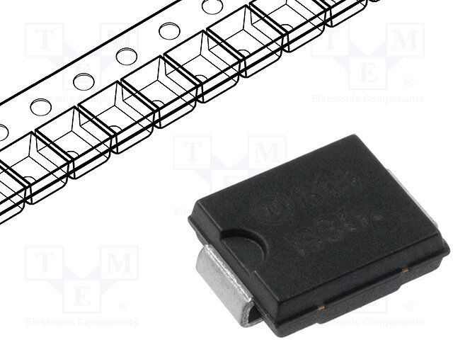
ICGOO电子元器件商城为您提供S3A由Fairchild Semiconductor设计生产,在icgoo商城现货销售,并且可以通过原厂、代理商等渠道进行代购。 S3A价格参考¥1.19-¥1.19。Fairchild SemiconductorS3A封装/规格:二极管 - 整流器 - 单, 标准 表面贴装 二极管 50V 3A SMC(DO-214AB)。您可以下载S3A参考资料、Datasheet数据手册功能说明书,资料中有S3A 详细功能的应用电路图电压和使用方法及教程。
S3A是安森美半导体(ON Semiconductor)生产的一款单整流二极管,广泛应用于各类电子设备中。该型号具有较高的可靠性和稳定性,适用于需要高效整流的电路设计。

主要应用场景包括:

1. 电源适配器与充电器:用于将交流电转换为直流电,常见于手机、笔记本电脑等便携设备的电源模块中。

2. 开关电源(SMPS):在AC/DC转换电路中作为整流元件,提升电源效率并减小体积。

3. 逆变器与UPS系统:在不间断电源和逆变器中用于整流环节,保障电力供应稳定。

4. 工业控制设备:如PLC、工业计算机等自动化设备中的电源部分,确保系统稳定运行。

5. 消费类电子产品:如电视、音响、LED照明等产品中的电源管理模块。

S3A具备3A电流能力和50V反向耐压,适合中低功率应用,具备良好的热稳定性和耐用性,是性价比高且可靠的通用整流二极管解决方案。
| 参数 | 数值 |
| 产品目录 | |
| 描述 | DIODE GEN PURPOSE 50V 3A SMC整流器 50V 3a Rectifier Glass Passive |
| 产品分类 | 单二极管/整流器分离式半导体 |
| 品牌 | Fairchild Semiconductor |
| 产品手册 | |
| 产品图片 |
|
| rohs | RoHS 合规性豁免无铅 / 符合限制有害物质指令(RoHS)规范要求 |
| 产品系列 | 二极管与整流器,整流器,Fairchild Semiconductor S3A- |
| 数据手册 | |
| 产品型号 | S3A |
| 不同If时的电压-正向(Vf) | 1.2V @ 3A |
| 不同 Vr、F时的电容 | 60pF @ 4V,1MHz |
| 不同 Vr时的电流-反向漏电流 | 5µA @ 50V |
| 二极管类型 | 标准 |
| 产品 | Standard Recovery Rectifiers |
| 产品目录页面 | |
| 产品种类 | 整流器 |
| 供应商器件封装 | SMC (DO-214AB) |
| 其它名称 | S3AFSCT |
| 功率耗散 | 2.6 W |
| 包装 | 剪切带 (CT) |
| 单位重量 | 300 mg |
| 反向恢复时间(trr) | 2.5µs |
| 反向电压 | 50 V |
| 反向电流IR | 5 uA |
| 商标 | Fairchild Semiconductor |
| 安装类型 | 表面贴装 |
| 安装风格 | SMD/SMT |
| 封装 | Reel |
| 封装/外壳 | DO-214AB,SMC |
| 封装/箱体 | SMC |
| 工作温度-结 | -55°C ~ 150°C |
| 工厂包装数量 | 3000 |
| 恢复时间 | 2500 ns |
| 最大工作温度 | + 150 C |
| 最大浪涌电流 | 100 A |
| 最小工作温度 | - 55 C |
| 标准包装 | 1 |
| 正向电压下降 | 1.2 V |
| 正向连续电流 | 3 A |
| 热阻 | 47°C/W Ja |
| 电压-DC反向(Vr)(最大值) | 50V |
| 电流-平均整流(Io) | 3A |
| 系列 | S3A |
| 速度 | 标准恢复 >500ns,> 200mA(Io) |
| 配置 | Single |
| 零件号别名 | S3A_NL |


PDF Datasheet 数据手册内容提取
Series S Low Capacity Standard Size Toggles ss ee GENERAL SPECIFICATIONS FOR S100s AA glgl gg oo TT s Electrical Capacity (Resistive & Inductive Load) er k c Power Level: Shown in the following table Ro s n Other Ratings o utt Contact Resistance: 10 milliohms maximum hb s Insulation Resistance: 200 megohms minimum @ 500V DC Pu Dielectric Strength: 1,500V AC minimum for 1 minute minimum B P Mechanical Life: 30,000 operations minimum d e Electrical Life: 10,000 operations minimum at n Operating Temp Range: –10°C through +70°C (+14°F through +158°F) mi u Ill e bl Materials & Finishes ma m Toggle: Brass with chrome plating gra o Bushing: Brass with chrome or nickel plating Pr Case: Phenolic resin Case Cover: Steel with zinc plating ks c o Movable Contactor Plate: Copper with silver plating yl e Movable & Stationary Contacts: Silver alloy plus copper with silver plating K Terminals: Copper with silver plating s e Environmental Data ari ot R Operating Temp Range: –10°C through +70°C (+14°F through +158°F) s Installation e d Mounting Torque: 2.94Nm (26 lb•in) for double nut Sli Soldering Time & Temperature: Manual Soldering: See Profile A in Supplement section. s e Standards & Certifications ctil a T CSA: File No. 023535_0_000 - Certified only when ordered with marking on switch. Add “/C” to end of part number to order CSA certified switch. Certified at 5A @ 125V AC & 2A @ 250V AC. Tilt h c u o T s or at c di n I s e ori s s e c c A nt e m e pl p u S www.nkkswitches.com A101
Series S Low Capacity Standard Size Toggles s e glA DOUBLE POLE WITH SOLDER LUG g o T * CSA certified only when ordered with Toggle Position/Connected Terminals Electrical Capacity marking on switch (see General Specs) ers *Approvals Down Center Up Resistive Inductive k Roc Model PThorleo w& Keyway 1A25CV 2A50CV 3D0CV APCF 1 02.56V ofA Tnhgrloew R ns S114 –– DPST ON 2-1 5-4 NONE OFF — 5A 2A 5A 3A 25° o butt S116 –– DPDT ON 2-1 5-4 NONE ON 2-3 5-6 5A 2A 5A 3A 25° h s Pu S116R –– –– DPDT ON 2-1 5-4 NONE ON 2-3 5-6 5A 2A 5A 3A 25° B d P Throw & DPST 2 (COM) 5 DPDT 2 (COM) 5 Note: Terminal numbers are ate Schematics: 1 4 1 3 4 6 actually on the switch n mi u Ill Notes: Standard Hardware: AT504M Knurled Nut, AT508 Lockwasher, AT527M Backup Hex Nut. See Accessories & Hardware section. e bl Optional Splashproof Boot Assemblies (only for bat lever models): AT401 & AT4181 boots plus hex nut and o-ring. See Accessories & Hardware section. a m m a gr o Pr S114 & S116 S116R Black Polyamide Paddle s k c o eyl Keyway M12 P1 .(027.09) Dia Typ (9.0) K .354 (12.5) Dia .492 (10.35) Typ 6 3 s 25° ( 4.4.00)7 5 2 (12.079.84) (.1415.53) otarie .(263.06) Dia (5.5) (3.1.58 (.7)20 T.9y30p) Dia 4 1 (0.8) Typ . 0(16.50) R .217 .150 .031 (17.6) (18.0) (10.0) (22.9) (4.0) (29.0) (0.3) Typ .693 .709 .394 .902 .157 1.142 .012 Maximum s e Panel Thickness: d Sli S116 S114 does not have terminals 3 & 6 .158” (4.0mm) s e ctil a T Tilt h c u o T s or at c di n I s e ori s s e c c A nt e m e pl p u S A102 www.nkkswitches.com
Series S Medium Capacity Standard Size Toggles s e GENERAL SPECIFICATIONS FOR S1 ~ S29 A gl g o T Electrical Capacity (Resistive & Inductive Load) s er Power Level: Shown in the following tables k c o R Other Ratings s n Contact Resistance: 10 milliohms maximum o utt Insulation Resistance: 1,000 megohms minimum @ 500V DC b h s Dielectric Strength: 2,000V AC minimum for 1 minute minimum u P Mechanical Life: 30,000 operations minimum for S5AW, S8AW, S9AW, S25AW, S28AW, S29AW B P 50,000 operations minimum for all other models d e Electrical Life: 25,000 operations minimum at n Angle of Throw (α): Shown in tables on following pages mi u Ill e bl Materials & Finishes a m m Toggle: Brass with chrome plating a gr Bushing: Brass with chrome plating o Pr Case: Phenolic resin Case Cover: Steel with zinc plating ks c Movable Contactor: Copper with silver plating ylo e Movable Contacts: Silver alloy capped on copper with silver plating K Stationary Contacts: Silver alloy capped on copper with silver plating Terminals: Brass with tin plating s e ari ot Environmental Data R Operating Temp Range: –30°C through +70°C (–22°F through +158°F) for Splashproof models; –10°C through +70°C (+14°F through +158°F) for all other models s e Sealing: Splashproof & lever lock panel seal models meet IP67 standard Slid Installation Mounting Torque: 12..4974NNmm ((1236 llbb••iinn)) ffoorr sdionugblele n nuut to onn A oWth e&r mALo dmeolsdels actiles T Maximum Panel Thickness: Shown beneath panel cutout in switch dimension drawings Soldering Time & Temperature: Manual Soldering: See Profile A in Supplement section. Standards & Certifications Tilt UL: File No. E44145 - Recognized only when ordered with marking on switch. Add “/U” or “/CUL” to end of part number to order UL recognized switch. UL or cULus recognition designated beside part numbers on following pages. h c See Supplement section to find UL or cULus rating details. ou T CSA: File No. 023535_0_000 - Certified only when ordered with marking on switch. Add “/C” to end of part number to order CSA certified switch. ors CSA certification designated beside part numbers on following pages. at c See Supplement section to find CSA rating details. di n I s e ori s s e c c A nt e m e pl p u S www.nkkswitches.com A103 7/28/17
Series S Medium Capacity Standard Size Toggles s e glA SINGLE POLE WITH SOLDER LUG g o T * UL, cULus & CSA recognized only when ordered Toggle Position/Connected Terminals Electrical Capacity with marking on switch (see General Specs) s *Approvals Down Center Up Resistive Inductive er ck Pole & Keyway AC AC DC AC 125V Angle Ro Model R C RUS Throw 125V 250V 30V PF 0.6 of Throw S1A SPST ON 1-3 NONE OFF — 15A 6A 20A 8A 25° s n S2A SPDT ON 2-3 NONE ON 2-1 15A 6A 20A 8A 25° o butt S3A SPDT ON 2-3 OFF ON 2-1 15A 6A 20A 8A 25° h s Pu Throw & SPST INTERNAL SPDT 2 (COM) Note: Terminal numbers are d PB Schematics: 1 3 CONNECTION 3 1 actually on the switch e at n Notes: Standard Hardware: AT504M Knurled Nut, AT508 Lockwasher, AT527M Backup Hex Nut. See Accessories & Hardware section. mi u Optional Splashproof Boot Assemblies: AT401 & AT4181 boots plus hex nut & o-ring. See Accessories & Hardware section. Ill e bl a m Keyway (2.4) Dia Typ m M12 P1 .094 a Progr (.00.381) Typ 3 (.1429.25) Dia s 25° (.418.89) Typ 2 ( 31.018.01) (.1415.53) k oc 1 (1.5) eyl (6.0) Dia .060 K .236 (5.7) .224 (18.0) (17.5) (10.0) (23.7) s .709 .689 .394 .933 Maximum otarie S2A S1A does not have terminal 2 P.a1n5e8l” T (h4ic.0knmemss): R DOUBLE POLE WITH SOLDER LUG s Slide * UwL, icthU Lmuas r&ki nCgS Ao nr escwoigtcnhiz (esdee o Gnleyn werhael nS poerdcse)red Toggle Position/Connected Terminals Electrical Capacity *Approvals Down Center Up Resistive Inductive α= Pole & Keyway AC AC DC AC 125V Angle es Model R C RUS Throw 125V 250V 30V PF 0.6 of Throw actil S21A – – – – –– DPST ON 1-3 4-6 NONE OFF — 15A 15A 15A 8A 21° T S6A DPDT ON 2-3 5-6 NONE ON 2-1 5-4 20A 10A 20A 8A 21° S7A –– –– DPDT ON 2-3 5-6 OFF ON 2-1 5-4 20A 10A 20A 8A 28° Tilt TShchroewm a&ti cs: DPST ICNOTNERNNEACLTION DPDT 2 (COM) 5 N o t e : aTecrtumainllya lo nnu tmheb esrws iatcrhe 1 3 4 6 3 1 6 4 Notes: Standard Hardware: AT504M Knurled Nut, AT508 Lockwasher, AT527M Backup Hex Nut. See Accessories & Hardware section. h c Optional Splashproof Boot Assemblies: AT401 & AT4181 boots plus hex nut & o-ring. See Accessories & Hardware section. u o T ors Keyway M12 P1 .(029.44) Dia Typ at c ndi 6 3 (.1429.25) Dia I α (.418.89) Typ (13.21.228) (.1415.53) es 5 2 essori .(263.06) Dia 4 1 . 0(16.50) cc (5.7) A .224 (18.6) (17.5) (10.0) (25.7) (0.8) Typ nt .732 .689 .394 1.012 .031 Maximum e Panel Thickness: m e S6A S21A does not have terminals 2 & 5 .158” (4.0mm) pl p u S A104 www.nkkswitches.com
Series S Medium Capacity Standard Size Toggles s e SINGLE POLE WITH QUICK CONNECT A gl g o T Toggle Position/Connected Terminals Electrical Capacity Approvals Down Center Up Resistive Inductive s Pole & Keyway AC AC DC AC 125V Angle cker Model R Throw 125V 250V 30V PF 0.6 of Throw Ro S1F –– –– SPST ON 1-3 NONE OFF — 15A 6A 20A 8A 25° S2F –– –– SPDT ON 2-3 NONE ON 2-1 15A 6A 20A 8A 25° ns o S3F –– –– SPDT ON 2-3 OFF ON 2-1 15A 6A 20A 8A 25° utt b h s 2 (COM) u Throw & INTERNAL Note: Terminal numbers are P Schematics: SPST 1 3 CONNECTION SPDT 3 1 actually on the switch PB d e Notes: Standard Hardware: AT504M Knurled Nut, AT508 Lockwasher, AT527M Backup Hex Nut. See Accessories & Hardware section. nat mi Optional Splashproof Boot Assemblies: AT401 & AT4181 boots plus hex nut & o-ring. See Accessories & Hardware section. u Ill e bl Keyway (7.9) (0.8) Typ a M12 P1 .311 .031 m m a .(279.55) Typ 3 (.1429.25) Dia ogr Pr 25° (6.2.3550) Typ 2 ( 31.018.01) (.1415.53) s .(263.06) Dia .(016.50) Dia Typ 1 . 0(16.50) eylock K (11.7) .461 (18.0) (17.5) (10.0) (29.7) .709 .689 .394 1.169 Maximum s S1F does not have terminal 2 P.a1n5e8l” T (h4ic.0knmemss): S2F otarie R DOUBLE POLE WITH QUICK CONNECT s e Toggle Position/Connected Terminals Electrical Capacity d Sli Approvals Down Center Up Resistive Inductive α= Pole & Keyway AC AC DC AC 125V Angle Model Throw 125V 250V 30V PF 0.6 of Throw s R e S21F –– –– DPST ON 1-3 4-6 NONE OFF — 15A 15A 15A 8A 21° actil T S6F –– –– DPDT ON 2-3 5-6 NONE ON 2-1 5-4 20A 10A 20A 8A 21° S7F –– –– DPDT ON 2-3 5-6 OFF ON 2-1 5-4 20A 10A 20A 8A 28° Throw & INTERNAL 2 (COM) 5 Note: Terminal numbers are Tilt Schematics: DPST CONNECTION DPDT actually on the switch 1 3 4 6 3 1 6 4 Notes: Standard Hardware: AT504M Knurled Nut, AT508 Lockwasher, AT527M Backup Hex Nut. See Accessories & Hardware section. h Optional Splashproof Boot Assemblies: AT401 & AT4181 boots plus hex nut & o-ring. See Accessories & Hardware section. uc o T (7.9) Keyway .311 M12 P1 . 0(1 .6.(25709.) 55D) iTay pTyp 6 3 (.1429.25) Dia cators α ( 6.2.3550) Typ (13.21.228) (.1415.53) Indi 5 2 4 1 (1.5) .(263.06) Dia .060 ories (11.8) Note: S21F ss .465 (11.7) e (18.6) (17.5) (10.0) (31.8) .461 (0.8) Typ cc .732 .689 .394 1.253 .031 A Maximum nt Panel Thickness: me S21F does not have terminals 2 & 5 .158” (4.0mm) S6F e pl p u S www.nkkswitches.com A105
Series S Medium Capacity Standard Size Toggles s e glA SINGLE POLE SOLDER LUG WITH PANEL SEAL g o T Toggle Position/Connected Terminals Electrical Capacity ( ) = Momentary ckers Approvals Pole & KDeyowwayn Center Up AC ResAisCtive DC Aαng=le Ro Model R Throw 125V 250V 30V of Throw S1AW –– –– SPST ON 1-3 NONE OFF — 15A 6A 20A 24° s S2AW –– –– SPDT ON 2-3 NONE ON 2-1 15A 6A 20A 24° n o utt S3AW –– –– SPDT ON 2-3 OFF ON 2-1 15A 6A 20A 28° b h S5AW –– –– SPDT ON 2-3 NONE (ON) 2-1 15A 6A 20A 20° s u P S8AW –– –– SPDT (ON) 2-3 OFF (ON) 2-1 15A 6A 20A 24° B S9AW –– –– SPDT ON 2-3 OFF (ON) 2-1 15A 6A 20A 24° P ated Throw & SPST INTERNAL SPDT 2 (COM) Note: Terminal numbers are min Schematics: 1 3 CONNECTION 3 1 actually on the switch u Ill Notes: Standard Hardware: AT503M Face Hex Nut, AT508 Lockwasher, AT537 O-ring. See Accessories & Hardware section. ble For .250” Quick Connect terminals, add “F” to end of part number. See Quick Connect terminal dimensions on previous page. ma For further information, contact factory. m a (17.0) Dia (2.4) Dia Typ gr .669 .094 o Pr Flat (0.8) Typ .031 3 cks (.1402.99) α (.418.89) Typ 2 ( 31.018.01) .(4131.71) o eyl 1 (.1429.25) Dia K (5.7) Dia M12 P1 .224 (7.5) (5.7) .295 .224 aries (.1780.09) (.1678.59) (.1429.25) (.2933.37) S1AW does not have PanMeal xThimicukmness: ot S2AW terminal 2 .158” (4.0mm) R DOUBLE POLE SOLDER LUG WITH PANEL SEAL s Slide Toggle Pos(i t i)o =n /MCoomnneenctaterdy Terminals Electrical Capacity Approvals Down Center Up Resistive α= Pole & Keyway AC AC DC Angle ctiles SM21oAdWel R–– –– TDhProSwT ON 1-3 4-6 NONE OFF — 11255AV 21550AV 1350AV of 2Th2r°ow a T S6AW –– –– DPDT ON 2-3 5-6 NONE ON 2-1 5-4 20A 10A 20A 22° S7AW –– –– DPDT ON 2-3 5-6 OFF ON 2-1 5-4 20A 10A 20A 28° S25AW –– –– DPDT ON 2-3 5-6 NONE (ON) 2-1 5-4 15A 6A 20A 20° Tilt S28AW –– –– DPDT (ON) 2-3 5-6 OFF (ON) 2-1 5-4 15A 6A 20A 22° S29AW –– –– DPDT ON 2-3 5-6 OFF (ON) 2-1 5-4 15A 6A 20A 22° 2 (COM) 5 Throw & DPST INTERNAL DPDT Note: Terminal numbers are Schematics: CONNECTION actually on the switch h 1 3 4 6 3 1 6 4 c u To Notes: Standard Hardware: AT503M Face Hex Nut, AT508 Lockwasher, AT537 O-ring. See Accessories & Hardware section. For .250” Quick Connect terminals, add “F” to end of part number. See Quick Connect terminal dimensions on previous page. For further information, contact factory. s or (17.0) Dia (2.4) Dia Typ at .669 .094 dic Flat n 6 3 I es (.1402.99) α (.418.89) Typ 5 2 (13.21.228) .(4131.71) ori 4 1 (.1429.25) Dia ess .(252.74) Dia M12 P1 cc (7.5) (5.7) A .295 .224 (18.6) (17.5) (12.5) (25.7) (0.8) Typ nt .732 .689 .492 1.012 .031 Maximum me Panel Thickness: e S6AW S21AW does not have terminals 2 & 5 .158” (4.0mm) pl p u S A106 www.nkkswitches.com
Series S Medium Capacity Standard Size Toggles s e SINGLE POLE SOLDER LUG WITH LOCKING LEVER & PANEL SEAL A gl g o T Toggle Position/Connected Terminals Electrical Capacity Approvals Pole & KDeyowwayn Center Up AC ResAisCtive DC IAndC u1c2t5ivVe Aαn g=le ckers Model R C RUS Throw 125V 250V 30V PF 0.6 of Throw Ro S1AL –– –– SPST ON 1-3 NONE OFF — 15A 6A 20A 8A 24° S2AL –– –– SPDT ON 2-3 NONE ON 2-1 15A 6A 20A 8A 24° ns o S3AL –– –– SPDT ON 2-3 OFF ON 2-1 15A 6A 20A 8A 28° utt b h 2 (COM) us Throw & SPST INTERNAL SPDT Note: Terminal numbers are P Schematics: 1 3 CONNECTION 3 1 actually on the switch PB d e Notes: Standard Hardware: AT503M Face Hex Nut, AT508 Lockwasher, AT537 O-ring. See Accessories & Hardware section. nat mi u Ill e (7.4) Dia Flat .(029.44) Dia Typ mabl .291 m .(370.87) Dia (.00.381) Typ 3 ogra α (.418.89) Typ 2 ( 31.018.01) (.1414.21) Pr 1 (12.2) Dia ks ( 1.402.71) Dia M12 P1 .(279.55) .480 eyloc (23.5) (12.0) (5.7) K .925 .472 .224 (18.0) (26.4) (17.0) (23.7) .709 1.039 .669 .933 Maximum s e Panel Thickness: ari S1AL does not have terminal 2 .158” (4.0mm) S2AL ot R DOUBLE POLE SOLDER LUG WITH LOCKING LEVER & PANEL SEAL s * UL & cULus recognized only when de ordered with marking on switch Toggle Position/Connected Terminals Electrical Capacity Sli (see General Specs) *Approvals Down Center Up Resistive Inductive Keyway α = Model R C RUS PThorleo w& 1A25CV 2A50CV 3D0CV APCF 1 02.56V ofA Tnhgrloew ctiles a S21AL –– –– DPST ON 1-3 4-6 NONE OFF — 15A 15A 15A 8A 22° T S6AL DPDT ON 2-3 5-6 NONE ON 2-1 5-4 20A 10A 20A 8A 22° S7AL –– –– DPDT ON 2-3 5-6 OFF ON 2-1 5-4 20A 10A 20A 8A 28° Throw & DPST INTERNAL DPDT 2 (COM) 5 Note: Terminal numbers are Tilt Schematics: CONNECTION actually on the switch 1 3 4 6 3 1 6 4 Notes: Standard Hardware: AT503M Face Hex Nut, AT508 Lockwasher, AT537 O-ring. See Accessories & Hardware section. h c u o T (7 (..728.9)4 D1) iDaia Flat .(029.44) Dia Typ ators .307 6 3 dic α (.418.89) Typ (13.21.228) (.1414.21) In 5 2 ( 1.402.71) Dia M12 P1 .(279.55) 4 1 (.1428.02) Dia ssories (23.5) (12.0) (5.7) e .925 .472 .224 cc (18.6) (26.4) (17.0) (25.7) (0.8) Typ A .732 1.039 .669 1.012 .031 Maximum nt Panel Thickness: e m S21AL does not have terminals 2 & 5 .158” (4.0mm) S6AL e pl p u S www.nkkswitches.com A107
Series S Medium/High Capacity Standard Size Toggles s e glA GENERAL SPECIFICATIONS FOR S301 ~ S339 g o T s er k Electrical Capacity (Resistive & Inductive Load) c o R Power Level: Shown in the following tables s n o utt Other Ratings b h s Contact Resistance: 10 milliohms maximum u P Insulation Resistance: 1,000 megohms minimum @ 500V DC B d P Dielectric Strength: 2,000V AC minimum for 1 minute minimum ate Mechanical Life: 50,000 operations minimum n mi Electrical Life: 6,000 operations minimum for S331F; 15,000 operations minimum for all other S331s; u Ill 25,000 operations minimum for all others ble Angle of Throw (α): Shown on following tables a m m a gr Materials & Finishes o Pr Toggle: PBT for flatted lever; brass with chrome plating for all others Bushing: Brass with chrome plating s k c Case: Melamine phenol o eyl Case Cover: Steel with zinc plating K Movable Contactor: Copper with silver plating Movable & Stationary Contacts: Silver alloy capped on copper with silver plating s e Terminals: Brass with tin plating ari ot R Environmental Data Operating Temperature Range: –10°C ~ +70°C (+14°F ~ +158°F) s e d Sli Installation Mounting Torque: 2.94Nm (26 lb•in) for double nut; 1.47Nm (13 lb•in) for single nut Soldering Time & Temperature: Manual Soldering: See Profile A in Supplement section. s e ctil Ta Standards & Certifications UL: File No. E44145 - Recognized only when ordered with marking on switch. Add “/U” or “/CUL” to end of part number to order UL recognized switch. Tilt USeLe o Sr ucpUpLluesm reencto sgencittiioonn tdoe fisingdn aUteL do rb ceUsiLdues praatritn ngu dmebtaeirlss .o n following pages. CSA: File No. 023535_0_000 - Certified only when ordered with marking on switch. h Add “/C” to end of part number to order CSA certified switch. c u CSA certification designated beside part numbers on following pages. o T See Supplement section to find CSA rating details s or at c di n I s e ori s s e c c A nt e m e pl p u S A108 www.nkkswitches.com
Series S Medium/High Capacity Standard Size Toggles s e SINGLE POLE WITH SOLDER LUG A gl g o T * UL, cULus & CSA recognized only when ordered Toggle Position/Connected Terminals Electrical Capacity with marking on switch (see General Specs) ( ) = Momentary Model R *ApCproRUvSals PThorleo w& KDeyowwayn Center Up 1A25CV Re2sA5is0CtVive 3D0CV IAnPdCF u1 0c2t.56ivVe ofA Tnhgrloew Rockers S301 SPST ON 1-3 NONE OFF — 15A 6A 20A 10A 32° S302 SPDT ON 2-3 NONE ON 2-1 15A 6A 20A 10A 32° ns o S303 SPDT ON 2-3 OFF ON 2-1 15A 6A 20A 10A 32° utt b S305 –– –– SPDT ON 2-3 NONE (ON) 2-1 15A 6A 20A 8A 32° h s u S308 –– –– SPDT (ON) 2-3 OFF (ON) 2-1 15A 6A 20A 8A 32° P S309 –– –– SPDT ON 2-3 OFF (ON) 2-1 15A 6A 20A 8A 32° PB d 2 (COM) e Throw & INTERNAL Note: Terminal numbers are at Schematics: SPST 1 3 CONNECTION SPDT 3 1 actually on the switch min u Notes: Standard Hardware: AT503M Face Hex Nut, AT506M Locking Ring, AT508 Lockwasher, AT527M Backup Hex Nut. See Accessories & Hardware section. Ill e Optional Splashproof Boot Assemblies: AT401 & AT4181 boots plus hex nut & o-ring. See Accessories & Hardware section. abl m m a Keyway M12 P1 (.312.26) Dia Typ Progr 3 (12.5) Dia .492 ks 32° .(263.06) Typ 2 (12.182.52) (9.0) yloc .354 Ke (1.6) Typ 1 (3.0) Dia (6.1) Dia .063 .118 .240 s (.1663.00) (.1678.59) (.1427.20) (.1678.45) (.93.768) Max S301 does not PanMela Txhimicuknme s s: otarie have terminal 2 .185” (4.7mm) S301 R DOUBLE POLE WITH SOLDER LUG s e d * UL, cULus & CSA recognized only when ordered Toggle Position/Connected Terminals Electrical Capacity Sli with marking on switch (see General Specs) ( ) = Momentary *Approvals Down Center Up Resistive Inductive α = Pole & Keyway AC AC DC AC 125V Angle es Model R C RUS Throw 125V 250V 30V PF 0.6 of Throw ctil a S331 DPST ON 1-3 4-6 NONE OFF — 25A 25A 25A 10A 25° T S332 DPDT ON 2-3 5-6 NONE ON 2-1 5-4 25A 15A 25A 10A 25° S333 DPDT ON 2-3 5-6 OFF ON 2-1 5-4 25A 15A 25A 10A 30° S335 DPDT ON 2-3 5-6 NONE (ON) 2-1 5-4 15A 6A 20A 8A 25° Tilt S338 –– DPDT (ON) 2-3 5-6 OFF (ON) 2-1 5-4 15A 6A 20A 8A 25° S339 –– DPDT ON 2-3 5-6 OFF (ON) 2-1 5-4 15A 6A 20A 8A 25° 2 (COM) 5 Throw & INTERNAL Note: Terminal numbers are h Schematics: DPST 1 3 4 6 CONNECTION DPDT 3 1 6 4 actually on the switch uc o T Notes: Standard Hardware: AT503M Face Hex Nut, AT506M Locking Ring, AT508 Lockwasher, AT527M Backup Hex Nut. See Accessories & Hardware section. Optional Splashproof Boot Assemblies: AT401 & AT4181 boots plus hex nut & o-ring. See Accessories & Hardware section. s or Keyway (2.4) Dia Typ at .094 c M12 P1 di n I 6 3 (12.5) Dia .492 s α (.418.89) Typ 54 21 (13.330.27) .(395.04) essorie (3.0) Dia c (6.1) Dia .118 Ac .240 (5.7) (.1794.80) (.1678.59) (.1427.02) (.2958.81) .224 S331 does not have PanMela Txhimicuknme ss: ment e terminals 2 & 5 .185” (4.7mm) S331 pl p u S www.nkkswitches.com A109
Series S Medium/High Capacity Standard Size Toggles s e glA DOUBLE POLE WITH SOLDER LUG & FLATTED LEVER g o T * UL & cULus recognized only when ordered Toggle Position/Connected Terminals with marking on switch Electrical Capacity ( ) = Momentary (see General Specs) s ker *Approvals Down Center Up Resistive Inductive c Ro α = Pole & Keyway AC AC DC AC 125V Angle R Model R C US Throw 125V 250V 30V PF 0.6 of Throw s n utto S331R –– DPST ON 1-3 4-6 NONE OFF — 25A 25A 25A 10A 25° hb S332R –– DPDT ON 2-3 5-6 NONE ON 2-1 5-4 25A 15A 25A 10A 25° s u P S333R –– DPDT ON 2-3 5-6 OFF ON 2-1 5-4 25A 15A 25A 10A 30° PB S338R –– DPDT (ON) 2-3 5-6 OFF (ON) 2-1 5-4 15A 6A 20A 8A 25° d ate S339R –– DPDT ON 2-3 5-6 OFF (ON) 2-1 5-4 15A 6A 20A 8A 25° n umi Throw & DPST DPDT 2 (COM) 5 Note: Terminal numbers are Ill Schematics: ICNOTNERNNEACLTION actually on the switch e 1 3 4 6 3 1 6 4 bl a m am Notes: Standard Hardware: AT504M Knurled Nut, AT508 Lockwasher, AT527M Backup Hex Nut. See Accessories & Hardware section. gr o Pr s ck Keyway (2.4) Dia Typ o .094 yl M12 P1 e K 6 3 (12.5) Dia .492 aries α (.418.89) Typ 54 21 (13.330.27) .(395.04) ot (3.0) Dia R .118 (4.0) (8.15) .157 .321 (5.7) .224 (9.0) (27.0) (12.0) (25.1) (19.0) .354 1.063 .472 .988 .748 s e Slid S331R does not have PanMela Txhimicuknmess: S331R terminals 2 & 5 .220” (5.6mm) s e ctil a T Tilt h c u o T s or at c di n I s e ori s s e c c A nt e m e pl p u S A110 www.nkkswitches.com
Series S Medium/High Capacity Standard Size Toggles s e SINGLE POLE WITH SCREW LUG A gl g o T * UL, cULus & CSA recognized only when ordered Toggle Position/Connected Terminals Electrical Capacity with marking on switch (see General Specs) ( ) = Momentary *Approvals Down Center Up Resistive Inductive α = ers Pole & Keyway AC AC DC AC 125V Angle ock Model R C RUS Throw 125V 250V 30V PF 0.6 of Throw R S301T SPST ON 1-3 NONE OFF — 15A 6A 20A 10A 32° s S302T SPDT ON 2-3 NONE ON 2-1 15A 6A 20A 10A 32° on S303T SPDT ON 2-3 OFF ON 2-1 15A 6A 20A 10A 32° butt h S305T –– –– SPDT ON 2-3 NONE (ON) 2-1 15A 6A 20A 8A 32° us P S308T –– –– SPDT (ON) 2-3 OFF (ON) 2-1 15A 6A 20A 8A 32° B S309T –– –– SPDT ON 2-3 OFF (ON) 2-1 15A 6A 20A 8A 32° d P e Throw & SPST INTERNAL SPDT 2 (COM) Note: Terminal numbers are nat Schematics: 1 3 CONNECTION 3 1 actually on the switch umi Ill Notes: Standard Hardware: AT503M Face Hex Nut, AT506M Locking Ring, AT508 Lockwasher, AT527M Backup Hex Nut. See Accessories & Hardware section. ble Optional Splashproof Boot Assemblies: AT401 & AT4181 boots plus hex nut & o-ring. See Accessories & Hardware section. ma m a Keyway M12 P1 M3.5 P0.5 gr o Pr (12.5) Dia .492 32° .(263.06) Typ (12.182.52) (9.0) ocks .354 yl (5.0) Typ e .197 (3.0) Dia K (6.1) Dia .118 .240 (16.0) (17.5) (12.0) (17.4) (9.6) Max s .630 .689 .472 .685 .378 S301T does not have PanMela Txhimicuknmess: otarie terminal 2 .185” (4.7mm) S301T R DOUBLE POLE WITH SCREW LUG s e * UL &m caUrkLuinsg r eocno sgwniiztcehd (soenely G wehneenra ol rSdpeercesd) with Toggle Pos(i t i)o =n /MCoomnneenctaterdy Terminals Electrical Capacity Slid *Approvals Down Center Up Resistive Inductive α = Pole & Keyway AC AC DC AC 125V Angle es Model R C RUS Throw 125V 250V 30V PF 0.6 of Throw ctil a S331T –– DPST ON 1-3 4-6 NONE OFF — 15A 15A 15A 10A 25° T S332T –– DPDT ON 2-3 5-6 NONE ON 2-1 5-4 15A 15A 15A 10A 25° S333T –– DPDT ON 2-3 5-6 OFF ON 2-1 5-4 15A 15A 15A 10A 30° S335T –– DPDT ON 2-3 5-6 NONE (ON) 2-1 5-4 15A 6A 20A 8A 25° Tilt S338T –– DPDT (ON) 2-3 5-6 OFF (ON) 2-1 5-4 15A 6A 20A 8A 25° S339T –– DPDT ON 2-3 5-6 OFF (ON) 2-1 5-4 15A 6A 20A 8A 25° 2 (COM) 5 Note: Terminal numbers are Throw & DPST INTERNAL DPDT h Schematics: 1 3 4 6 CONNECTION 3 1 6 4 actually on the switch uc o T Notes: Standard Hardware: AT503M Face Hex Nut, AT506M Locking Ring, AT508 Lockwasher, AT527M Backup Hex Nut. See Accessories & Hardware section. Optional Splashproof Boot Assemblies: AT401 & AT4181 boots plus hex nut & o-ring. See Accessories & Hardware section. s Keyway M12 P1 M3.5 x 5 ator c di n I 6 3 (12.5) Dia .492 25° .(266.60) 5 2 (13.330.27) .(395.04) ories 4 1 (3.0) Dia ess .(264.10) Dia .118 Acc (6.6) .260 (.1794.08) (.1678.59) (.1427.02) (12.062.04) .(013.09) Typ Maximum ent m S331T does not have Panel Thickness: e pl terminals 2 & 5 .185” (4.7mm) S331T p u S www.nkkswitches.com A111
Series S Medium/High Capacity Standard Size Toggles s e glA SINGLE POLE WITH QUICK CONNECT g o T * UL, cULus & CSA recognized only when ordered Toggle Position/Connected Terminals Electrical Capacity with marking on switch (see General Specs) ers *Approvals Down Center Up Resistive Inductive α = ock Pole & Keyway AC AC DC AC 125V Angle R Model R C RUS Throw 125V 250V 30V PF 0.6 of Throw s S301F SPST ON 1-3 NONE OFF — 15A 6A 20A 10A 32° n o utt shb Throw & SPST INTERNAL Note: Terminal numbers are u Schematics: CONNECTION actually on the switch P 1 3 B P d Notes: Standard Hardware: AT503M Face Hex Nut, AT506M Locking Ring, AT508 Lockwasher, AT527M Backup Hex Nut. See Accessories & Hardware section. e nat Optional Splashproof Boot Assemblies: AT401 & AT4181 boots plus hex nut & o-ring. See Accessories & Hardware section. mi u Ill mable Keyway M12 P1 .(016.50) Dia Typ m (0.8) Typ a .031 3 (12.5) Dia gr .492 Pro 32° (12.182.52) (9.0) .354 ks 1 (3.0) Dia c (6.1) Dia .118 ylo .240 (9.42) (6.35) Typ e .371 .250 K (16.0) (17.5) (12.0) (17.4) (11.0) (7.5) Typ .630 .689 .472 .685 .433 .295 Maximum s Panel Thickness: e ari S301F .185” (4.7mm) ot R DOUBLE POLE WITH QUICK CONNECT * UL & cULus recognized only when ordered with Toggle Position/Connected Terminals s Electrical Capacity e marking on switch (see General Specs) ( ) = Momentary d Sli *Approvals Down Center Up Resistive Inductive α = Pole & Keyway AC AC DC AC 125V Angle Model R C RUS Throw 125V 250V 30V PF 0.6 of Throw s ctile S331F –– DPST ON 1-3 4-6 NONE OFF — 25A 25A 25A 10A 25° Ta S332F –– DPDT ON 2-3 5-6 NONE ON 2-1 5-4 25A 15A 25A 10A 25° S333F –– DPDT ON 2-3 5-6 OFF ON 2-1 5-4 25A 15A 25A 10A 30° S335F –– DPDT ON 2-3 5-6 NONE (ON) 2-1 5-4 15A 6A 20A 8A 25° Tilt Throw & DPST INTERNAL DPDT 2 (COM) 5 Note: Terminal numbers are Schematics: CONNECTION actually on the switch 1 3 4 6 3 1 6 4 Notes: Standard Hardware: AT503M Face Hex Nut, AT506M Locking Ring, AT508 Lockwasher, AT527M Backup Hex Nut. See Accessories & Hardware section. h c u Optional Splashproof Boot Assemblies: AT401 & AT4181 boots plus hex nut & o-ring. See Accessories & Hardware section. o T ators Keyway M12 P1 (.73.191) .(016.50) Dia Typ ndic (.72.955) Typ 6 3 (.1429.25) Dia I ories α ( 6.2.3550) Typ 54 21 (13.330.27) (3.0) D .(39i5a.04) ss (6.1) Dia .118 e .240 cc (11.7) A .461 (19.0) (17.5) (12.0) (30.3) (0.8) Typ .748 .689 .472 1.193 .031 nt Maximum me Panel Thickness: ple S332F S331F does not have terminals 2 & 5 .185” (4.7mm) p u S A112 www.nkkswitches.com
Series S Medium/High Capacity Standard Size Toggles s e GENERAL SPECIFICATIONS FOR S31 ~ S49 A gl g o T Electrical Capacity (Resistive & Inductive Load) s Power Level: Shown in the following tables er k c o R Other Ratings s n o Contact Resistance: 10 milliohms maximum utt b Insulation Resistance: 1,000 megohms minimum @ 500V DC h s u Dielectric Strength: 2,000V AC minimum for 1 minute minimum P Mechanical Life: 50,000 operations minimum B P Electrical Life: 25,000 operations minimum ed at Angle of Throw (α): Shown on following tables n mi u Ill e Materials & Finishes abl m m Toggle: PBT resin for flatted lever; brass with chrome plating for all others a Bushing: Brass with chrome plating ogr Pr Case: Phenolic resin Case Cover: Steel with chromate plating over zinc plating s k c Movable Contactor: Copper with silver plating o yl Movable Contacts: Silver alloy capped on copper with silver plating Ke Stationary Contacts: Silver alloy capped on copper with silver plating Terminals: Brass with tin plating s e ari ot R Environmental Data Operating Temp Range: –10°C through +70°C (+14°F through +158°F) s e d Sli Installation Mounting Torque: 2.94Nm (26 lb•in) for double nut Maximum Panel Thickness: Shown beneath panel cutout in switch dimension drawings es Soldering Time & Temperature: Manual Soldering: See Profile A in Supplement section. actil T Standards & Certifications Tilt UL: File No. E44145 - Recognized only when ordered with marking on switch. Add “/U” or “/CUL” to end of part number to order UL recognized switch. UL or cULus recognition designated beside part numbers on following pages. See Supplement section to find UL or cULus rating details. ch u o T CSA: File No. 023535_0_000 - Certified only when ordered with marking on switch. Add “/C” to end of part number to order CSA certified switch. s CSA certification designated beside part numbers on following pages. or at See Supplement section to find CSA rating details. c di n I s e ori s s e c c A nt e m e pl p u S www.nkkswitches.com A113
Series S Medium/High Capacity Standard Size Toggles s e glA THREE POLE WITH SOLDER LUG g o T * UL, cULus & CSA recognized only when ordered Toggle Position/Connected Terminals Electrical Capacity with marking on switch (see General Specs) ( ) = Momentary s *Approvals Down Center Up Resistive Inductive α = ker Pole & Keyway AC AC DC AC 125V Angle Roc Model R C RUS Throw 125V 250V 30V PF 0.6 of Throw S31 3PST ON 1-3 4-6 7-9 NONE OFF — 25A 9A 20A 10A 25° s S32 3PDT ON 2-3 5-6 8-9 NONE ON 2-1 5-4 8-7 25A 9A 20A 10A 25° n utto S33 3PDT ON 2-3 5-6 8-9 OFF ON 2-1 5-4 8-7 25A 9A 20A 10A 30° hb S35 3PDT ON 2-3 5-6 8-9 NONE (ON) 2-1 5-4 8-7 15A 6A 20A 8A 25° s Pu S38 3PDT (ON) 2-3 5-6 8-9 OFF (ON) 2-1 5-4 8-7 15A 6A 15A 8A 25° B S39 3PDT ON 2-3 5-6 8-9 OFF (ON) 2-1 5-4 8-7 15A 6A 15A 8A 25° P d 2 5 (COM) 8 ate Throw & 3PST INTERNAL 3PDT Note: Terminal numbers min Schematics: 1 3 4 6 7 9 CONNECTION 3 1 6 4 9 7 are on the switch u Ill Notes: Standard Hardware: AT503M Face Hex Nut, AT506M Locking Ring, AT508 Lockwasher, AT527M Backup Hex Nut. See Accessories & Hardware section. e bl Optional Splashproof Boot Assemblies: AT401 & AT4181 boots plus hex nut & o-ring. See Accessories & Hardware section. a mm Keyway .(029.44) Dia Typ a M12 P1 Progr (.00.381) Typ 9 6 3 (12.5) Dia .492 cks α (.418.89) Typ 8 5 2 (13.333.81) (9.0) o .354 yl 7 1 Ke (6.1) Dia 4 (.311.80) Dia .240 (5.0) Maximum .197 S31 does not have Panel Thickness: es S32 ( 31.018.01) (.1678.59) (.1427.02) (12.077.35) terminals 2, 5, & 8 .181” (4.6mm) ari ot R FOUR POLE WITH SOLDER LUG * UL, cULus & CSA recognized only when ordered Toggle Position/Connected Terminals Electrical Capacity with marking on switch (see General Specs) ( ) = Momentary s e Slid SuMffioxd Rel = *Approvals Pole & KeDywoawy n Center Up AC ResAisCtive DC AInCd u1c2ti5vVe Aαn g=le Flatted Lever R C RUS Throw 125V 250V 30V PF 0.6 of Throw S41/S41R 4PST ON 1-3 4-6 7-9 10-12 NONE OFF — 25A 9A 20A 10A 25° s e S42/S42R 4PDT ON 2-3 5-6 8-9 11-12 NONE ON 2-1 5-4 8-7 11-10 25A 9A 20A 10A 25° actil S43/S43R 4PDT ON 2-3 5-6 8-9 11-12 OFF ON 2-1 5-4 8-7 11-10 25A 9A 20A 10A 30° T S45 – –– 4PDT ON 2-3 5-6 8-9 11-12 NONE (ON) 2-1 5-4 8-7 11-10 15A 6A 20A 8A 25° S48/S48R –– 4PDT (ON) 2-3 5-6 8-9 11-12 OFF (ON) 2-1 5-4 8-7 11-10 15A 6A 20A 8A 25° S49/S49R –– 4PDT ON 2-3 5-6 8-9 11-12 OFF (ON) 2-1 5-4 8-7 11-10 15A 6A 20A 8A 25° Tilt 4PST 4PDT 2 5 (COM) 8 11 Note: Terminal Throw & INTERNAL numbers are Schematics: CONNECTION 1 3 4 6 7 9 10 12 3 1 6 4 9 7 12 10 on the switch h Notes: Standard Hardware for Bat Lever: AT503M Face Hex Nut, AT506M Locking Ring, AT508 Lockwasher, AT527M Backup Hex Nut; c ou for Flatted Lever (R): AT504M Knurled Face Nut, AT508 Lockwasher, AT527M Backup Hex Nut. See Accessories & Hardware section. T Optional Splashproof Boot Assemblies (only for bat lever models): AT401 & AT4181 boots plus hex nut and o-ring. See Accessories & Hardware section. (12.5) Dia .492 s or (2.4) Dia Typ (11.5) at Keyway .094 .453 c M12 P1 di (1.5) In (.00.381) Typ 12 9 6 3 Max. Pan.0e6l0 Thickness: es α (.418.89) Typ 8 (13.344.26) .220” (5.6mm) ssori 1110 7 54 21 (.1429.25) Dia e c (4.0) (8.15) Ac .157 .321 (5.8) .(395.04) .228 nt .(395.04) (12.076.03) (.1427.20) 1(2.076.17) (13.463.57) (.311.80) Dia e m e Max. Panel Thickness: ppl S42R Bat lever dimensions are same as on S30 models above. S41 and S41R do not have terminals 2, 5, 8, & 11. .181” (4.6mm) u S A114 www.nkkswitches.com
Series S Medium/High Capacity Standard Size Toggles s e THREE POLE WITH SCREW LUG A gl g o T * UL, cULus & CSA recognized only when ordered Toggle Position/Connected Terminals Electrical Capacity with marking on switch (see General Specs) *Approvals Down Center Up Resistive Inductive α = kers Pole & Keyway AC AC DC AC 125V AC 250V Angle oc Model R C RUS Throw 125V 250V 30V PF 0.6 PF 0.6 of Throw R S31T 3PST ON 1-3 4-6 7-9 NONE OFF — 25A 9A 20A 10A 5A 25° s n S32T 3PDT ON 2-3 5-6 8-9 NONE ON 2-1 5-4 8-7 25A 9A 20A 10A 5A 25° o utt S33T 3PDT ON 2-3 5-6 8-9 OFF ON 2-1 5-4 8-7 25A 9A 20A 10A 5A 30° hb s u P Throw & 3PST INTERNAL 3PDT 2 5 (COM) 8 Note: Terminal numbers B Schematics: 1 3 4 6 7 9 CONNECTION 3 1 6 4 9 7 are on the switch d P e at n Notes: Standard Hardware: AT503M Face Hex Nut, AT506M Locking Ring, AT508 Lockwasher, AT527M Backup Hex Nut. See Accessories & Hardware section. mi u Optional Splashproof Boot Assemblies: AT401 & AT4181 boots plus hex nut & o-ring. See Accessories & Hardware section. Ill e Keyway M12 P1 M3.5 x 5 bl a m m a 9 6 3 (12.5) Dia ogr .492 Pr 25° (33.8) 1.331 8 5 2 .(395.04) ks 7 4 1 (.311.80) Dia yloc (6.1) Dia e .240 K (7.5) .295 (30.0) (17.5) (12.0) (29.8) Maximum 1.181 .689 .472 1.173 S31T does not have terminals 2, 5, & 8 P.a1n8e1l” T (h4ic.6knmemss): S32T otaries R FOUR POLE WITH SCREW LUG * UL, cULus & CSA recognized only when es ordered wiGthe mnearrakli nSgp eocns) switch (see Toggle Position/Connected Terminals Electrical Capacity Slid *Approvals Down Center Up Resistive Inductive Pole α = Model R C RUS Thr&o w Keyway 1A25CV 2A50CV 3D0CV P1FA2 05C.V 6 P2FA5 00C.V 6 ofA Tnhgrloew ctiles a S41T 4PST ON 1-3 4-6 7-9 10-12 NONE OFF — 25A 9A 20A 10A 5A 25° T S42T 4PDT ON 2-3 5-6 8-9 11-12 NONE ON 2-1 5-4 8-7 11-10 25A 9A 20A 10A 5A 25° S43T 4PDT ON 2-3 5-6 8-9 11-12 OFF ON 2-1 5-4 8-7 11-10 25A 9A 20A 10A 5A 30° 4PST 4PDT Tilt Note: Throw & 2 5 (COM) 8 11 Terminal numbers Schematics: INTERNAL CONNECTION are on the switch 1 3 4 6 7 9 10 12 3 1 6 4 9 7 12 10 h Notes: Standard Hardware: AT503M Face Hex Nut, AT506M Locking Ring, AT508 Lockwasher, AT527M Backup Hex Nut. See Accessories & Hardware section. uc o Optional Splashproof Boot Assemblies: AT401 & AT4181 boots plus hex nut & o-ring. See Accessories & Hardware section. T Keyway M12 P1 M3.5 x 5 s or at c 25° 12 98 6 3 (13.344.26) (.1429.25) Dia Indi 1101 7 54 21 (3.0) D .(39i5a.04) ories .118 s .(264.10) Dia ces (8.3) Ac .327 (13.489.06) (.1678.59) (.1427.02) (12.196.65) (13.463.57) Maximum ent m Panel Thickness: e S41T does not have terminals 2, 5, 8, & 11 .181” (4.6mm) S42T pl p u S www.nkkswitches.com A115
Series S Medium/High Capacity Standard Size Toggles s e glA THREE POLE WITH QUICK CONNECT g o T * UL, cULus & CSA recognized only when ordered Toggle Position/Connected Terminals Electrical Capacity with marking on switch (see General Specs) kers *Approvals Down Center Up Resistive Inductive α = oc Pole & Keyway AC AC DC AC 125V Angle R Model R C RUS Throw 125V 250V 30V PF 0.6 of Throw S31F 3PST ON 1-3 4-6 7-9 NONE OFF — 25A 9A 20A 10A 25° s n utto S32F 3PDT ON 2-3 5-6 8-9 NONE ON 2-1 5-4 8-7 25A 9A 20A 10A 25° hb S33F 3PDT ON 2-3 5-6 8-9 OFF ON 2-1 5-4 8-7 25A 9A 20A 10A 30° s u P B Throw & 3PST INTERNAL 3PDT 2 5 (COM) 8 Note: Terminal numbers d P Schematics: 1 3 4 6 7 9 CONNECTION 3 1 6 4 9 7 are on the switch e at n mi Notes: Standard Hardware: AT503M Face Hex Nut, AT506M Locking Ring, AT508 Lockwasher, AT527M Backup Hex Nut. See Accessories & Hardware section. u Ill Optional Splashproof Boot Assemblies: AT401 & AT4181 boots plus hex nut & o-ring. See Accessories & Hardware section. e bl ma Keyway (.73.191) ogram M12 P1 .(01 6.(570.) 5D) iTay pTyp 6 Pr .295 9 3 (.1429.25) Dia 25° (6.35) Typ (33.8) ocks .250 87 5 21 1.331 .(395.04) Keyl .(264.10) Dia (.00.381) Typ 4 (.311.80) Dia (11.0) .433 (30.0) (17.5) (12.0) (33.3) s 1.181 .689 .472 1.311 Maximum e ari Panel Thickness: ot S32F S31F does not have terminals 2, 5, & 8 .181” (4.6mm) R FOUR POLE WITH QUICK CONNECT s e d * UL, cULus & CSA recognized only when ordered Sli with marking on switch (see General Specs) Toggle Position/Connected Terminals Electrical Capacity *Approvals Down Center Up Resistive Inductive α = s Pole & Keyway AC AC DC AC 125V Angle ctile Model R C RUS Throw 125V 250V 30V PF 0.6 of Throw a T S41F 4PST ON 1-3 4-6 7-9 10-12 NONE OFF — 25A 9A 20A 10A 25° S42F 4PDT ON 2-3 5-6 8-9 11-12 NONE ON 2-1 5-4 8-7 11-10 25A 9A 20A 10A 25° S43F 4PDT ON 2-3 5-6 8-9 11-12 OFF ON 2-1 5-4 8-7 11-10 25A 9A 20A 10A 30° Tilt 4PST 4PDT Note: Terminal Throw & 2 5 (COM) 8 11 numbers are Schematics: INTERNAL 1 3 4 6 7 9 10 12 CONNECTION 3 1 6 4 9 7 12 10 on the switch h uc Notes: Standard Hardware: AT503M Face Hex Nut, AT506M Locking Ring, AT508 Lockwasher, AT527M Backup Hex Nut. See Accessories & Hardware section. o T Optional Splashproof Boot Assemblies: AT401 & AT4181 boots plus hex nut & o-ring. See Accessories & Hardware section. Keyway (7.9) s .311 ator M12 P1 .(016.50) Dia Typ Indic 25° .( (26.729..35555)0 T) yTpyp 12 98 6 3 (13.344.26) (.1429.25) Dia essories .(263.06) Dia (.00.381) Typ 1110 7 54 21 (.311.80) D .(39i5a.04) c Ac (.1416.85) (36.5) (17.5) (12.0) (33.1) nt 1.437 .689 .472 1.303 Maximum e m Panel Thickness: e pl S42F S41F does not have terminals 2, 5, 8, & 11 .181” (4.6mm) p u S A116 www.nkkswitches.com
Series S Medium/High Capacity Standard Size Toggles s e GENERAL SPECIFICATIONS FOR S421 ~ S429 A gl g o T Electrical Capacity (Resistive & Inductive Load) ers k c Power Level: Shown in the following tables o R Other Ratings ns o Contact Resistance: 10 milliohms maximum butt h Insulation Resistance: 1,000 megohms minimum @ 500V DC us P Dielectric Strength: 2,000V AC minimum for 1 minute minimum B Mechanical Life: 50,000 operations minimum d P e Electrical Life: 15,000 operations minimum at n Angle of Throw (α): Shown in tables on following pages mi u Ill e Materials & Finishes abl m m Toggle: Brass with chrome plating a gr Bushing: Brass with chrome plating Pro Case: Melamine phenol Case Cover: Steel with chromate plating over zinc plating ks c o Movable Contactor: Copper with silver plating yl e Movable Contacts: Silver alloy capped on copper with silver plating K Stationary Contacts: Silver alloy capped on copper with silver plating Terminals: Brass with tin plating s e ari ot Environmental Data R Operating Temp Range: –10°C through +70°C (+14°F through +158°F) s e d Installation Sli Mounting Torque: 2.94Nm (26 lb•in) for double nut Maximum Panel Thickness: Shown beneath panel cutout in switch dimension drawings s e Soldering Time & Temperature: Manual Soldering: See Profile A in Supplement section. ctil a T Tilt h c u o T s or at c di n I s e ori s s e c c A nt e m e pl p u S www.nkkswitches.com A117
Series S Medium/High Capacity Standard Size Toggles s e glA DOUBLE POLE WITH SOLDER LUG g o T Toggle Position/Connected Terminals Electrical Capacity ( ) = Momentary Rockers Approvals Pole & KDeyowwayn Center Up ARCesistivAeC PFIn 0d.7u5ct -iv 0e.8 MLoAoaCtodr Aαn g=le Model R Throw 125V 250V AC 125V AC 250V 125V of Throw S421 –– –– DPST ON 1-3 4-6 NONE OFF — 25A 25A 25A 25A 750W 24° s n utto S422 –– –– DPDT ON 2-3 5-6 NONE ON 2-1 5-4 25A 25A 25A 25A 750W 24° b S423 –– –– DPDT ON 2-3 5-6 OFF ON 2-1 5-4 25A 25A 25A 25A 750W 28° h s Pu S425 –– –– DPDT ON 2-3 5-6 NONE (ON) 2-1 5-4 15A 15A 15A 15A 400W 24° B S428 –– –– DPDT (ON) 2-3 5-6 OFF (ON) 2-1 5-4 15A 15A 15A 15A 400W 24° P d S429 –– –– DPDT ON 2-3 5-6 OFF (ON) 2-1 5-4 15A 15A 15A 15A 400W 24° e minat Throw & DPST INTERNAL DPDT 2 (COM) 5 Note: Terminal numbers u Schematics: CONNECTION are on the switch Ill 1 3 4 6 3 1 6 4 e bl Notes: Standard Hardware: AT503M Face Hex Nut, AT506M Locking Ring, AT508 Lockwasher, AT527M Backup Hex Nut. See Accessories & Hardware section. a m Optional Splashproof Boot Assemblies: AT401 & AT4181 boots plus hex nut & o-ring. See Accessories & Hardware section. m a ogr Keyway M12 P1 .(029.44) Dia Typ Pr ks 6 3 (12.5) Dia c .492 o Keyl α (.418.89) Typ 5 2 (13.330.27) .(395.04) 4 1 (3.0) Dia .118 (6.1) Dia es .240 (5.7) otari (.1794.80) (.1678.59) (.1427.02) (.2958.81) .224 (.00.381) Typ PanMela Txhimicuknme ss: R S422 S421 does not have terminals 2 & 5 .185” (4.7mm) DOUBLE POLE WITH SCREW LUG s e d Sli Toggle Position/Connected Terminals Electrical Capacity ( ) = Momentary Approvals Down Center Up Resistive Inductive Motor s Load α = Tactile Model R PThorleo w& Keyway 1A25CV 2A50CV AC 1P2F5 0V.75 A- C0 .2850V 1A25CV ofA Tnhgrloew S421T –– –– DPST ON 1-3 4-6 NONE OFF — 20A 20A 20A 20A 750W 24° S422T –– –– DPDT ON 2-3 5-6 NONE ON 2-1 5-4 20A 20A 20A 20A 750W 24° S423T –– –– DPDT ON 2-3 5-6 OFF ON 2-1 5-4 20A 20A 20A 20A 750W 28° Tilt S425T –– –– DPDT ON 2-3 5-6 NONE (ON) 2-1 5-4 15A 15A 15A 15A 400W 24° S428T –– –– DPDT (ON) 2-3 5-6 OFF (ON) 2-1 5-4 15A 15A 15A 15A 400W 24° S429T –– –– DPDT ON 2-3 5-6 OFF (ON) 2-1 5-4 15A 15A 15A 15A 400W 24° 2 (COM) 5 ch Throw & DPST INTERNAL DPDT Note: Terminal numbers Tou Schematics: 1 3 4 6 CONNECTION 3 1 6 4 are on the switch Notes: Standard Hardware: AT503M Face Hex Nut, AT506M Locking Ring, AT508 Lockwasher, AT527M Backup Hex Nut. See Accessories & Hardware section. s Optional Splashproof Boot Assemblies: AT401 & AT4181 boots plus hex nut & o-ring. See Accessories & Hardware section. or at Keyway M12 P1 M4 X 5 c di n I 6 3 (12.5) Dia es 5 .492 essori α 4 2 (13.330.27) .(395.04) Acc 1 (.311.80) Dia (6.1) Dia .240 ement (.1794.80) (.1678.59) (.1427.20) 1(.3212.14) (.1413.03) PanMela Txhimicuknme ss: ppl S423T S421T does not have terminals 2 & 5 .185” (4.7mm) u S A118 www.nkkswitches.com
Series S High Capacity Standard Size Toggles s e GENERAL SPECIFICATIONS FOR S800s ~ S732 A gl g o T Electrical Capacity (Resistive & Inductive Load) s er Power Level: Shown in the following tables ck o R s n Other Ratings utto b Contact Resistance: 10 milliohms maximum h s u Insulation Resistance: 1,000 megohms minimum @ 500V DC P Dielectric Strength: 2,000V AC minimum for 1 minute minimum for S800s & S800Ds B P 3,000V AC minimum for 1 minute minimum for S732 ed at Mechanical Life: 50,000 operations minimum n mi Electrical Life: 10,000 operations minimum for S800Ds u Ill 25,000 operations minimum for S800s & S732 e bl a m m a gr Materials & Finishes Pro Toggle: Brass with nickel plating for S732 s Brass with chrome plating for S800s & S800Ds ck o Bushing: Brass with chrome plating yl e K Case: Phenolic resin for S732; melamine phenol for S800s Case Cover: Steel with chromate plating over zinc plating Movable Contactor Plate: Copper with silver plating es Movable & Stationary Contacts: Silver alloy capped on copper with silver plating ari ot Common Terminals: Brass R Contact Terminals: Brass with silver or nickel plating s e d Sli Environmental Data Operating Temp Range: –10°C through +70°C (+14°F through +158°F) s e ctil a T Installation Mounting Torque: 2.94Nm (26 lb•in) for double nut Maximum Panel Thickness: Shown beneath panel cutout in switch dimension drawings Tilt Standards & Certifications h UL: File No. E44145 - Recognized only when ordered with marking on switch. uc o Add “/U” or “/CUL” to end of part number to order UL recognized switch. T UL or cULus recognition designated beside part numbers on following pages. See Supplement section to find UL or cULus rating details. s or at CSA: File No. 023535_0_000 - Certified only when ordered with marking on switch. dic n Add “/C” to end of part number to order CSA certified switch. I CSA certification designated beside part numbers on following pages. s See Supplement section to find CSA rating details. orie s s e c c A nt e m e pl p u S www.nkkswitches.com A119
Series S High Capacity Standard Size Toggles s e glA DOUBLE POLE WITH SCREW LUG g o T * UL, cULus & CSA recognized only when ordered with marking on switch Toggle Position/Connected Terminals Electrical Capacity (see General Specs) s cker *Approvals Down Center Up Resistive Inductive MLooatodr o R Pole & Keyway AC AC DC DC AC 125V AC 250V AC Model R C RUS Throw 125V 250V 30V 125V PF 0.6 PF 0.6 125V s on S821 DPST ON 2-3 5-6 NONE OFF — 30A 30A 30A 1A 30A 15A 750W butt S822 DPDT ON 2-3 5-6 NONE ON 2-1 5-4 30A 30A 30A 1A 30A 15A — h s u S823 DPDT ON 2-3 5-6 OFF ON 2-1 5-4 30A 30A 30A 1A 30A 15A — P PB Throw & DPST 2 (COM) 5 DPDT 2 (COM) 5 Note: Terminal numbers ated Schematics: 3 6 3 1 6 4 are on the switch n mi Notes: Standard Hardware: AT503M Face Hex Nut, AT506M Locking Ring, AT508 Lockwasher, AT527M Backup Hex Nut. See Accessories & Hardware section. u Ill Optional Splashproof Boot Assembly: AT401 boot plus hex nut & o-ring. See Accessories & Hardware section. e bl Keyway M4.5x6 a m am M12 P1 gr o Pr 6 3 (12.5) Dia .492 (42.0) ylocks 28° (.1427.20) Typ 54 21 1.654 (3.0) D .(39i5a.04) Ke (6.1) Dia .118 .240 (12.0) es .472 ari (22.0) (12.0) (34.0) (24.0) Maximum Rot .866 .472 1.339 .945 Panel Thickness: S822 S821 does not have terminals 1 & 4 .177” (4.5mm) s THREE POLE WITH SCREW LUG e d Sli * UL, cULus & CSA recognized only when ordered with marking on switch Toggle Position/Connected Terminals Electrical Capacity (see General Specs) *Approvals Down Center Up Resistive Inductive s e Tactil Model R C RUS PThorleo w& Keyway 1A25CV 2A50CV 3D0CV 1D25CV APCF 1 02.56V APCF 2 05.06V S831 3PST ON 2-3 5-6 8-9 NONE OFF — 30A 30A 30A 1A 30A 15A S832 3PDT ON 2-3 5-6 8-9 NONE ON 2-1 5-4 8-7 30A 30A 30A 1A 30A 15A Tilt S833 3PDT ON 2-3 5-6 8-9 OFF ON 2-1 5-4 8-7 30A 30A 30A 1A 30A 15A 2 5 (COM) 8 2 5 (COM) 8 Throw & 3PST 3PDT Note: Terminal numbers Schematics: are on the switch 3 6 9 3 1 6 4 9 7 h Notes: Standard Hardware: AT503M Face Hex Nut, AT506M Locking Ring, AT508 Lockwasher, AT527M Backup Hex Nut. See Accessories & Hardware section. c u o Optional Splashproof Boot Assembly: AT401 boot plus hex nut & o-ring. See Accessories & Hardware section. T Keyway M4.5x6 s M12 P1 or at 6 dic 9 3 (.1429.25) Dia In 28° (14.625.04) es (.1427.20) Typ 87 5 21 .(395.04) ssori .(264.10) Dia 4 (.311.80) Dia e c c A (14.5) Typ .571 ment (2.826.06) (.1427.02) (13.343.09) (14.639.03) PanMela Txhimicuknme ss: e pl S833 S831 does not have terminals 1, 4 & 7 .177” (4.5mm) p u S A120 www.nkkswitches.com
Series S High Capacity Standard Size Toggles s e DOUBLE POLE WITH SCREW LUG & FLATTED LEVER A gl g o T * UL, cULus & CSA recognized only when ordered with marking on Toggle Position/Connected Terminals Electrical Capacity switch (see General Specs) s *Approvals Down Center Up Resistive Inductive L/R = 3ms er k c Pole & Keyway DC DC DC DC DC DC DC DC DC Ro Model R C RUS Throw 30V 48V 125V 250V 400V 24V 48V 125V 250V S821D DPST ON 2-3 5-6 NONE OFF — 30A 30A 20A 15A 4A (10A) 15A 10A 6A 3A s n o S822D DPDT ON 2-3 5-6 NONE ON 2-1 5-4 30A 30A 20A 15A 4A 15A 10A 6A 3A utt b S823D DPDT ON 2-3 5-6 OFF ON 2-1 5-4 30A 30A 15A 7.5A — 15A 10A 6A 3A h s u P ( ) capacity is due to wiring. Refer to instructions below. B P TShchroewm a&ti cs: DPST 3 2 (COM)6 5 DPDT 3 2 (C1OM)6 5 4 Note: Taerrem oinna thl ne usmwbitechrs minated u Notes: Standard Hardware: AT503M Face Hex Nut, AT506M Locking Ring, AT508 Lockwasher, AT527M Backup Hex Nut. See Accessories & Hardware section. Ill e bl a Double Pole m m Keyway M4.5x6 a gr M12 P1 Pro 6 3 (12.5) Dia 28° (14.625.04) .492 cks o (.1427.20) Typ 54 21 .(395.04) eyl K (4.0) (8.15) (3.0) Dia .157 .321 .118 (12.0) .472 s e .(395.04) (12.076.03) (.1427.02) (13.343.09) (2.944.05) Maximum otari R S821D does not Panel Thickness: have terminals 1 & 4 .177” (4.5mm) S822D s e d 400V DC WIRING INSTRUCTIONS Sli 1. DC Switch Use 3. Inductive Load s e • Middle terminal shall be the minus pole when using DC circuit. Inductive loads produce an arc caused by counter-electromotive force ctil Switch case is marked with (+) and (–). when opening the circuit. Recommend inserting spark elimination Ta circuit. Contact factory for details. • Do not store near (5cm) highly magnetic items. • If actuation is interrupted when switching from ON to OFF, arcing may continue and switch could be burned. Contact Point Tilt D R L + C 2. Wiring for DC400V 10A (Patent Pending) h c (2) (5) Tou (3) (6) 4. Compressed Terminal Connection 21 54 Contact Connection Position Wcomhepnr ecsosnende tcetrinmgin saclr euwsi ntegr mdrianwali nwgi thb ecloomw.pressed terminal, select ators Minus Pole c Connection di n I 3 6 s e ECxotnernneacltion PClounsn Peoclteio n 1 4 (9.8) essori 2 5 .386 cc A 3 6 ent m e pl p u S www.nkkswitches.com A121
Series S High Capacity Standard Size Toggles s e glA THREE POLE WITH SCREW LUG & FLATTED LEVER g o T * UL, cULus & CSA recognized only when ordered with marking on switch Toggle Position/Connected Terminals Electrical Capacity (see General Specs) s er *Approvals Down Center Up Resistive Inductive L/R = 3ms k c Ro Pole & Keyway DC DC DC DC DC DC DC DC Model R Throw 30V 48V 125V 250V 24V 48V 125V 250V R C US s S831D 3PST ON 2-3 5-6 8-9 NONE OFF — 30A 30A 15A 7.5A 15A 10A 6A 3A n o utt S832D 3PDT ON 2-3 5-6 8-9 NONE ON 2-1 5-4 8-7 30A 30A 15A 7.5A 15A 10A 6A 3A b h S833D 3PDT ON 2-3 5-6 8-9 OFF ON 2-1 5-4 8-7 30A 30A 15A 7.5A 15A 10A 6A 3A s u P B Throw & 2 5 (COM) 8 2 5 (COM) 8 Note: Terminal numbers P 3PST 3PDT ed Schematics: 3 6 9 3 1 6 4 9 7 are on the switch at n umi Notes: Standard Hardware: AT503M Face Hex Nut, AT506M Locking Ring, AT508 Lockwasher, AT527M Backup Hex Nut. See Accessories & Hardware section. Ill e bl a m Three Pole m a gr Keyway M4.5x6 o Pr M12 P1 s 6 ck 9 3 o Keyl 28° (14.625.04) (12.0) Typ 5 .472 87 21 4 s (4.0) (8.15) e .157 .321 ari ot R (14.5) Typ .571 (9.0) (27.0) (12.0) (34.0) (43.0) .354 1.063 .472 1.339 1.693 s e d Sli S831D does not have terminals 1, 4 & 7. Positive (+) must be connected to end terminals & negative to common terminals. s e ctil a T Tilt (12.5) Dia .492 ch .(395.04) u o (3.0) Dia T .118 ors Maximum at Panel Thickness: dic .177” (4.5mm) n I s e ori s s e c S832D c A nt e m e pl p u S A122 www.nkkswitches.com
Series S High Capacity Standard Size Toggles s e DOUBLE POLE WITH SCREW LUG A gl g o T Toggle Position/Connected Terminals Electrical Capacity Approvals Down Center Up Resistive Inductive s er Pole & Keyway AC AC DC AC 125V ck o Model R Throw 125V 250V 30V PF 0.6 R S732 –– –– DPDT ON 2-3 5-6 NONE ON 2-1 5-4 50A 30A 50A 25A s n o TShchroewm a&ti cs: DPDT 2 (COM) 5 Note: Terminal numbers are on the switch ushbutt 3 1 6 4 P B P Notes: Standard Hardware: AT503M Face Hex Nut, AT506M Locking Ring, AT508 Lockwasher, AT527M Backup Hex Nut. See Accessories & Hardware section. d e at n mi u Ill e bl Keyway M4 x 10 M6 x 8 ma m a gr o Pr 6 3 M12 P1 (17.0) Typ ks .669 oc (15.906.09) 32° 5 2 (26.03.602) Keyl s (10.0) Dia 4 1 arie .394 ot R (13.489.06) ( 21.91.651) (.1309.04) (13.593.05) (.1780.90) s e d Sli Cap of phenolic resin is black s Panel Mount with Mounting Screws ctile a T (4.5) Dia Typ (14.5) Dia .177 .571 Tilt (25.0) Typ .984 Maximum Panel Thickness: h .158” (4.0mm) c u o T Panel Mount with Bushing Hardware s or at (12.5) Dia (.1429.25) Dia dic .492 In (11.5) .453 (9.0) (3.0) D.3i5a4 (.1429.25) Dia . 0(16.50) ories .118 s s e Maximum Maximum Maximum cc A Panel Thickness: Panel Thickness: Panel Thickness: S732 .079” (2.0mm) .118” (3.0mm) .118” (3.0mm) nt e m e pl p u S www.nkkswitches.com A123
Mouser Electronics Authorized Distributor Click to View Pricing, Inventory, Delivery & Lifecycle Information: N KK Switches: S1A S3A S7A S1F S2A S6A S6F S1AW S1AL S3AL S29AWF-RO S7ALF S9AWF S2AWF S28AWF S1AWF S29AWF S28AW S9AW S21AL S29AW S6AL S6AW S21F S25AW S3AW S1B S7AW S7B S2AL S8AWF S21A S7F S5AW S1A/UC S6AWF S3B S21AWF S3F S6B S2B S2AW S8AW S21B S21AW S7AL S2F S3AWF S7AWF S5AWF