
 Datasheet下载
- 型号: S301T
- 制造商: NKK Switches
- 库位|库存: xxxx|xxxx
- 要求:
| 数量阶梯 | 香港交货 | 国内含税 |
| +xxxx | $xxxx | ¥xxxx |
查看当月历史价格
查看今年历史价格
S301T产品简介:
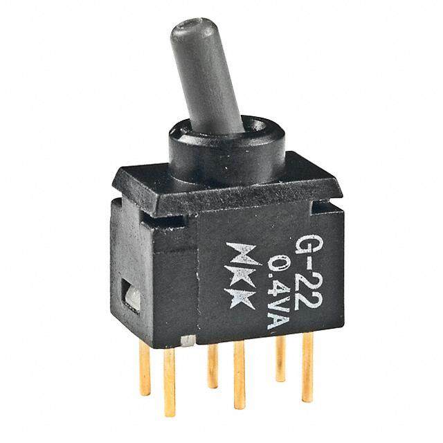
ICGOO电子元器件商城为您提供S301T由NKK Switches设计生产,在icgoo商城现货销售,并且可以通过原厂、代理商等渠道进行代购。 S301T价格参考¥60.52-¥84.15。NKK SwitchesS301T封装/规格:拨动开关, Toggle Switch SPST Panel Mount。您可以下载S301T参考资料、Datasheet数据手册功能说明书,资料中有S301T 详细功能的应用电路图电压和使用方法及教程。
NKK Switches的S301T是一款高品质的拨动开关,广泛应用于需要高可靠性和长寿命操作的工业与电子设备中。该型号具备紧凑设计、优异的电气性能和耐用性,适用于多种严苛环境。

典型应用场景包括:工业控制设备(如PLC控制箱、自动化控制系统)、医疗仪器(如监护仪、诊断设备)、测试与测量仪器(如示波器、电源供应器)、通信设备(如路由器、交换机)以及航空航天和军事电子系统。S3012T因其稳定的接触性能和抗干扰能力,也常用于需要频繁切换或关键操作的场合。

此外,S301T符合多项国际安全与环保标准(如UL、CSA、RoHS),适合出口型产品和对环保要求较高的应用。其多种档位配置(如单刀双掷、双刀双掷)和安装方式(面板安装)提供了灵活的设计选择,便于集成到各种设备面板中。

总之,S301T凭借其可靠性、长寿命(可达5万次以上机械寿命)和广泛的工作温度范围,成为工业与高端电子设备中理想的拨动开关解决方案。
| 参数 | 数值 |
| 产品目录 | |
| 描述 | SWITCH TOGGLE SPST 15A 125V拨动开关 SPST ON-OFF MED/HIGH SCREW LUG |
| 产品分类 | |
| 品牌 | NKK Switches |
| 产品手册 | |
| 产品图片 |
|
| rohs | RoHS 合规性豁免无铅 / 符合限制有害物质指令(RoHS)规范要求 |
| 产品系列 | 拨动开关,NKK Switches S301TS300 |
| mouser_ship_limit | 该产品可能需要其他文件才能进口到中国。 |
| 数据手册 | |
| 产品型号 | S301T |
| RoHS指令信息 | |
| 产品培训模块 | http://www.digikey.cn/PTM/IndividualPTM.page?site=cn&lang=zhs&ptm=7079 |
| 产品目录绘图 |
|
| 产品目录页面 | |
| 产品种类 | |
| 侵入防护 | - |
| 其它名称 | 360-1223 |
| 包装 | 散装 |
| 商标 | NKK Switches |
| 安装类型 | Bushing |
| 安装风格 | Panel |
| 工作温度 | -10°C ~ 70°C |
| 开关功能 | ON - NONE - OFF |
| 执行器 | Bat |
| 标准包装 | 1 |
| 照明 | 不发光 |
| 照明电压(标称值) | - |
| 照明类型,颜色 | - |
| 特性 | - |
| 特色产品 | http://www.digikey.com/cn/zh/ph/nkk/S300_S400_toggle_switches.html |
| 电压额定值AC | 125 V |
| 电气寿命 | 25,000 次循环 |
| 电路 | SPST |
| 相关产品 | /product-detail/zh/AT201/360-1001-ND/379088/product-detail/zh/AT202/360-1002-ND/379089/product-detail/zh/AT214/360-1003-ND/379090/product-detail/zh/AT402A/360-1606-ND/413710/product-detail/zh/AT401A/360-1605-ND/459915/product-detail/zh/AT402H/360-1706-ND/599025/product-detail/zh/AT402C/360-1707-ND/599026/product-detail/zh/AT402E/360-1708-ND/599027/product-detail/zh/AT402B/AT402B-ND/1045997/product-detail/zh/AT527M/360-3220-ND/1046026/product-detail/zh/AT401H/AT401H-ND/2103530/product-detail/zh/AT401S/360-2981-ND/2103531/product-detail/zh/AT402F/AT402F-ND/2103543 |
| 端子密封 | Sealed |
| 端子类型 | 螺丝端子 |
| 端接类型 | Screw |
| 系列 | S |
| 致动器材料 | 黄铜,镀铬 |
| 致动器类型 | 标准圆形 |
| 致动器长度 | 17.50mm |
| 衬套大小 | M12 |
| 衬套螺纹 | M12 x 1 |
| 触点形式 | SPST |
| 触点电镀 | Silver |
| 零件号别名 | S-301T |
| 面板开口尺寸 | 圆形 - 12.50mm 直径 |
| 额定电压-AC | 125V |
| 额定电压-DC | 30V |
| 额定电流 | 15A(AC),20A(DC) |


- 商务部:美国ITC正式对集成电路等产品启动337调查
- 曝三星4nm工艺存在良率问题 高通将骁龙8 Gen1或转产台积电
- 太阳诱电将投资9.5亿元在常州建新厂生产MLCC 预计2023年完工
- 英特尔发布欧洲新工厂建设计划 深化IDM 2.0 战略
- 台积电先进制程称霸业界 有大客户加持明年业绩稳了
- 达到5530亿美元!SIA预计今年全球半导体销售额将创下新高
- 英特尔拟将自动驾驶子公司Mobileye上市 估值或超500亿美元
- 三星加码芯片和SET,合并消费电子和移动部门,撤换高东真等 CEO
- 三星电子宣布重大人事变动 还合并消费电子和移动部门
- 海关总署:前11个月进口集成电路产品价值2.52万亿元 增长14.8%


PDF Datasheet 数据手册内容提取
Series S Medium/High Capacity Standard Size Toggles s e glA GENERAL SPECIFICATIONS FOR S301 ~ S339 g o T s er k Electrical Capacity (Resistive & Inductive Load) c o R Power Level: Shown in the following tables s n o utt Other Ratings b h s Contact Resistance: 10 milliohms maximum u P Insulation Resistance: 1,000 megohms minimum @ 500V DC B d P Dielectric Strength: 2,000V AC minimum for 1 minute minimum ate Mechanical Life: 50,000 operations minimum n mi Electrical Life: 6,000 operations minimum for S331F; 15,000 operations minimum for all other S331s; u Ill 25,000 operations minimum for all others ble Angle of Throw (α): Shown on following tables a m m a gr Materials & Finishes o Pr Toggle: PBT for flatted lever; brass with chrome plating for all others Bushing: Brass with chrome plating s k c Case: Melamine phenol o eyl Case Cover: Steel with zinc plating K Movable Contactor: Copper with silver plating Movable & Stationary Contacts: Silver alloy capped on copper with silver plating s e Terminals: Brass with tin plating ari ot R Environmental Data Operating Temperature Range: –10°C ~ +70°C (+14°F ~ +158°F) s e d Sli Installation Mounting Torque: 2.94Nm (26 lb•in) for double nut; 1.47Nm (13 lb•in) for single nut Soldering Time & Temperature: Manual Soldering: See Profile A in Supplement section. s ctile Ta Standards & Certifications UL: File No. E44145 - Recognized only when ordered with marking on switch. Add “/U” or “/CUL” to end of part number to order UL recognized switch. Tilt USeLe o Sr ucpUpLluesm reencto sgencittiioonn tdoe fisingdn aUteL do rb ceUsiLdues praatritn ngu dmebtaeirlss .o n following pages. CSA: File No. 023535_0_000 - Certified only when ordered with marking on switch. h Add “/C” to end of part number to order CSA certified switch. c u CSA certification designated beside part numbers on following pages. o T See Supplement section to find CSA rating details s or at c di n I s e ori s s e c c A nt e m e pl p u S A108 www.nkkswitches.com
Series S Medium/High Capacity Standard Size Toggles s e SINGLE POLE WITH SOLDER LUG A gl g o T * UL, cULus & CSA recognized only when ordered Toggle Position/Connected Terminals Electrical Capacity with marking on switch (see General Specs) ( ) = Momentary Model R *ApCproRUvSals PThorleo w& KDeyowwayn Center Up 1A25CV Re2sA5is0CtVive 3D0CV IAnPdCF u1 0c2t.56ivVe ofA Tnhgrloew Rockers S301 SPST ON 1-3 NONE OFF — 15A 6A 20A 10A 32° S302 SPDT ON 2-3 NONE ON 2-1 15A 6A 20A 10A 32° ns o S303 SPDT ON 2-3 OFF ON 2-1 15A 6A 20A 10A 32° utt b S305 –– –– SPDT ON 2-3 NONE (ON) 2-1 15A 6A 20A 8A 32° h s u S308 –– –– SPDT (ON) 2-3 OFF (ON) 2-1 15A 6A 20A 8A 32° P S309 –– –– SPDT ON 2-3 OFF (ON) 2-1 15A 6A 20A 8A 32° PB d 2 (COM) e Throw & INTERNAL Note: Terminal numbers are at Schematics: SPST 1 3 CONNECTION SPDT 3 1 actually on the switch min u Notes: Standard Hardware: AT503M Face Hex Nut, AT506M Locking Ring, AT508 Lockwasher, AT527M Backup Hex Nut. See Accessories & Hardware section. Ill e Optional Splashproof Boot Assemblies: AT401 & AT4181 boots plus hex nut & o-ring. See Accessories & Hardware section. abl m m a Keyway M12 P1 (.312.26) Dia Typ Progr 3 (12.5) Dia .492 ks 32° .(263.06) Typ 2 (12.182.52) (9.0) yloc .354 Ke (1.6) Typ 1 (3.0) Dia (6.1) Dia .063 .118 .240 s (.1663.00) (.1678.59) (.1427.20) (.1678.45) (.93.768) Max S301 does not PanMela Txhimicuknme s s: otarie have terminal 2 .185” (4.7mm) S301 R DOUBLE POLE WITH SOLDER LUG s e d * UL, cULus & CSA recognized only when ordered Toggle Position/Connected Terminals Electrical Capacity Sli with marking on switch (see General Specs) ( ) = Momentary *Approvals Down Center Up Resistive Inductive α = Pole & Keyway AC AC DC AC 125V Angle es Model R C RUS Throw 125V 250V 30V PF 0.6 of Throw ctil a S331 DPST ON 1-3 4-6 NONE OFF — 25A 25A 25A 10A 25° T S332 DPDT ON 2-3 5-6 NONE ON 2-1 5-4 25A 15A 25A 10A 25° S333 DPDT ON 2-3 5-6 OFF ON 2-1 5-4 25A 15A 25A 10A 30° S335 DPDT ON 2-3 5-6 NONE (ON) 2-1 5-4 15A 6A 20A 8A 25° Tilt S338 –– DPDT (ON) 2-3 5-6 OFF (ON) 2-1 5-4 15A 6A 20A 8A 25° S339 –– DPDT ON 2-3 5-6 OFF (ON) 2-1 5-4 15A 6A 20A 8A 25° 2 (COM) 5 Throw & INTERNAL Note: Terminal numbers are h Schematics: DPST 1 3 4 6 CONNECTION DPDT 3 1 6 4 actually on the switch uc o T Notes: Standard Hardware: AT503M Face Hex Nut, AT506M Locking Ring, AT508 Lockwasher, AT527M Backup Hex Nut. See Accessories & Hardware section. Optional Splashproof Boot Assemblies: AT401 & AT4181 boots plus hex nut & o-ring. See Accessories & Hardware section. s or Keyway (2.4) Dia Typ at .094 c M12 P1 di n I 6 3 (12.5) Dia .492 s α (.418.89) Typ 54 21 (13.330.27) .(395.04) essorie (3.0) Dia c (6.1) Dia .118 Ac .240 (5.7) (.1794.80) (.1678.59) (.1427.02) (.2958.81) .224 S331 does not have PanMela Txhimicuknme ss: ment e terminals 2 & 5 .185” (4.7mm) S331 pl p u S www.nkkswitches.com A109
Series S Medium/High Capacity Standard Size Toggles s e glA DOUBLE POLE WITH SOLDER LUG & FLATTED LEVER g o T * UL & cULus recognized only when ordered Toggle Position/Connected Terminals with marking on switch Electrical Capacity ( ) = Momentary (see General Specs) s ker *Approvals Down Center Up Resistive Inductive c Ro α = Pole & Keyway AC AC DC AC 125V Angle R Model R C US Throw 125V 250V 30V PF 0.6 of Throw s n utto S331R –– DPST ON 1-3 4-6 NONE OFF — 25A 25A 25A 10A 25° hb S332R –– DPDT ON 2-3 5-6 NONE ON 2-1 5-4 25A 15A 25A 10A 25° s u P S333R –– DPDT ON 2-3 5-6 OFF ON 2-1 5-4 25A 15A 25A 10A 30° PB S338R –– DPDT (ON) 2-3 5-6 OFF (ON) 2-1 5-4 15A 6A 20A 8A 25° d ate S339R –– DPDT ON 2-3 5-6 OFF (ON) 2-1 5-4 15A 6A 20A 8A 25° n umi Throw & DPST DPDT 2 (COM) 5 Note: Terminal numbers are Ill Schematics: ICNOTNERNNEACLTION actually on the switch e 1 3 4 6 3 1 6 4 bl a m am Notes: Standard Hardware: AT504M Knurled Nut, AT508 Lockwasher, AT527M Backup Hex Nut. See Accessories & Hardware section. gr o Pr s ck Keyway (2.4) Dia Typ o .094 yl M12 P1 e K 6 3 (12.5) Dia .492 aries α (.418.89) Typ 54 21 (13.330.27) .(395.04) ot (3.0) Dia R .118 (4.0) (8.15) .157 .321 (5.7) .224 (9.0) (27.0) (12.0) (25.1) (19.0) .354 1.063 .472 .988 .748 s e Slid S331R does not have PanMela Txhimicuknmess: S331R terminals 2 & 5 .220” (5.6mm) s e ctil a T Tilt h c u o T s or at c di n I s e ori s s e c c A nt e m e pl p u S A110 www.nkkswitches.com
Series S Medium/High Capacity Standard Size Toggles s e SINGLE POLE WITH SCREW LUG A gl g o T * UL, cULus & CSA recognized only when ordered Toggle Position/Connected Terminals Electrical Capacity with marking on switch (see General Specs) ( ) = Momentary *Approvals Down Center Up Resistive Inductive α = ers Pole & Keyway AC AC DC AC 125V Angle ock Model R C RUS Throw 125V 250V 30V PF 0.6 of Throw R S301T SPST ON 1-3 NONE OFF — 15A 6A 20A 10A 32° s S302T SPDT ON 2-3 NONE ON 2-1 15A 6A 20A 10A 32° on S303T SPDT ON 2-3 OFF ON 2-1 15A 6A 20A 10A 32° butt h S305T –– –– SPDT ON 2-3 NONE (ON) 2-1 15A 6A 20A 8A 32° us P S308T –– –– SPDT (ON) 2-3 OFF (ON) 2-1 15A 6A 20A 8A 32° B S309T –– –– SPDT ON 2-3 OFF (ON) 2-1 15A 6A 20A 8A 32° d P e Throw & SPST INTERNAL SPDT 2 (COM) Note: Terminal numbers are nat Schematics: 1 3 CONNECTION 3 1 actually on the switch umi Ill Notes: Standard Hardware: AT503M Face Hex Nut, AT506M Locking Ring, AT508 Lockwasher, AT527M Backup Hex Nut. See Accessories & Hardware section. ble Optional Splashproof Boot Assemblies: AT401 & AT4181 boots plus hex nut & o-ring. See Accessories & Hardware section. ma m a Keyway M12 P1 M3.5 P0.5 gr o Pr (12.5) Dia .492 32° .(263.06) Typ (12.182.52) (9.0) ocks .354 yl (5.0) Typ e .197 (3.0) Dia K (6.1) Dia .118 .240 (16.0) (17.5) (12.0) (17.4) (9.6) Max s .630 .689 .472 .685 .378 S301T does not have PanMela Txhimicuknmess: otarie terminal 2 .185” (4.7mm) S301T R DOUBLE POLE WITH SCREW LUG s e * UL &m caUrkLuinsg r eocno sgwniiztcehd (soenely G wehneenra ol rSdpeercesd) with Toggle Pos(i t i)o =n /MCoomnneenctaterdy Terminals Electrical Capacity Slid *Approvals Down Center Up Resistive Inductive α = Pole & Keyway AC AC DC AC 125V Angle es Model R C RUS Throw 125V 250V 30V PF 0.6 of Throw ctil a S331T –– DPST ON 1-3 4-6 NONE OFF — 15A 15A 15A 10A 25° T S332T –– DPDT ON 2-3 5-6 NONE ON 2-1 5-4 15A 15A 15A 10A 25° S333T –– DPDT ON 2-3 5-6 OFF ON 2-1 5-4 15A 15A 15A 10A 30° S335T –– DPDT ON 2-3 5-6 NONE (ON) 2-1 5-4 15A 6A 20A 8A 25° Tilt S338T –– DPDT (ON) 2-3 5-6 OFF (ON) 2-1 5-4 15A 6A 20A 8A 25° S339T –– DPDT ON 2-3 5-6 OFF (ON) 2-1 5-4 15A 6A 20A 8A 25° 2 (COM) 5 Note: Terminal numbers are Throw & DPST INTERNAL DPDT h Schematics: 1 3 4 6 CONNECTION 3 1 6 4 actually on the switch uc o T Notes: Standard Hardware: AT503M Face Hex Nut, AT506M Locking Ring, AT508 Lockwasher, AT527M Backup Hex Nut. See Accessories & Hardware section. Optional Splashproof Boot Assemblies: AT401 & AT4181 boots plus hex nut & o-ring. See Accessories & Hardware section. s Keyway M12 P1 M3.5 x 5 ator c di n I 6 3 (12.5) Dia .492 25° .(266.60) 5 2 (13.330.27) .(395.04) ories 4 1 (3.0) Dia ess .(264.10) Dia .118 Acc (6.6) .260 (.1794.08) (.1678.59) (.1427.02) (12.062.04) .(013.09) Typ Maximum ent m S331T does not have Panel Thickness: e pl terminals 2 & 5 .185” (4.7mm) S331T p u S www.nkkswitches.com A111
Series S Medium/High Capacity Standard Size Toggles s e glA SINGLE POLE WITH QUICK CONNECT g o T * UL, cULus & CSA recognized only when ordered Toggle Position/Connected Terminals Electrical Capacity with marking on switch (see General Specs) ers *Approvals Down Center Up Resistive Inductive α = ock Pole & Keyway AC AC DC AC 125V Angle R Model R C RUS Throw 125V 250V 30V PF 0.6 of Throw s S301F SPST ON 1-3 NONE OFF — 15A 6A 20A 10A 32° n o utt shb Throw & SPST INTERNAL Note: Terminal numbers are u Schematics: CONNECTION actually on the switch P 1 3 B P d Notes: Standard Hardware: AT503M Face Hex Nut, AT506M Locking Ring, AT508 Lockwasher, AT527M Backup Hex Nut. See Accessories & Hardware section. e nat Optional Splashproof Boot Assemblies: AT401 & AT4181 boots plus hex nut & o-ring. See Accessories & Hardware section. mi u Ill mable Keyway M12 P1 .(016.50) Dia Typ m (0.8) Typ a .031 3 (12.5) Dia gr .492 Pro 32° (12.182.52) (9.0) .354 ks 1 (3.0) Dia c (6.1) Dia .118 ylo .240 (9.42) (6.35) Typ e .371 .250 K (16.0) (17.5) (12.0) (17.4) (11.0) (7.5) Typ .630 .689 .472 .685 .433 .295 Maximum s Panel Thickness: e ari S301F .185” (4.7mm) ot R DOUBLE POLE WITH QUICK CONNECT * UL & cULus recognized only when ordered with Toggle Position/Connected Terminals s Electrical Capacity e marking on switch (see General Specs) ( ) = Momentary d Sli *Approvals Down Center Up Resistive Inductive α = Pole & Keyway AC AC DC AC 125V Angle Model R C RUS Throw 125V 250V 30V PF 0.6 of Throw s ctile S331F –– DPST ON 1-3 4-6 NONE OFF — 25A 25A 25A 10A 25° Ta S332F –– DPDT ON 2-3 5-6 NONE ON 2-1 5-4 25A 15A 25A 10A 25° S333F –– DPDT ON 2-3 5-6 OFF ON 2-1 5-4 25A 15A 25A 10A 30° S335F –– DPDT ON 2-3 5-6 NONE (ON) 2-1 5-4 15A 6A 20A 8A 25° Tilt Throw & DPST INTERNAL DPDT 2 (COM) 5 Note: Terminal numbers are Schematics: CONNECTION actually on the switch 1 3 4 6 3 1 6 4 Notes: Standard Hardware: AT503M Face Hex Nut, AT506M Locking Ring, AT508 Lockwasher, AT527M Backup Hex Nut. See Accessories & Hardware section. h c u Optional Splashproof Boot Assemblies: AT401 & AT4181 boots plus hex nut & o-ring. See Accessories & Hardware section. o T ators Keyway M12 P1 (.73.191) .(016.50) Dia Typ ndic (.72.955) Typ 6 3 (.1429.25) Dia I ories α ( 6.2.3550) Typ 54 21 (13.330.27) (3.0) D .(39i5a.04) ss (6.1) Dia .118 e .240 cc (11.7) A .461 (19.0) (17.5) (12.0) (30.3) (0.8) Typ .748 .689 .472 1.193 .031 nt Maximum me Panel Thickness: ple S332F S331F does not have terminals 2 & 5 .185” (4.7mm) p u S A112 www.nkkswitches.com
Series S Medium/High Capacity Standard Size Toggles s e GENERAL SPECIFICATIONS FOR S31 ~ S49 A gl g o T Electrical Capacity (Resistive & Inductive Load) s Power Level: Shown in the following tables er k c o R Other Ratings s n o Contact Resistance: 10 milliohms maximum utt b Insulation Resistance: 1,000 megohms minimum @ 500V DC h s u Dielectric Strength: 2,000V AC minimum for 1 minute minimum P Mechanical Life: 50,000 operations minimum B P Electrical Life: 25,000 operations minimum ed at Angle of Throw (α): Shown on following tables n mi u Ill e Materials & Finishes abl m m Toggle: PBT resin for flatted lever; brass with chrome plating for all others a Bushing: Brass with chrome plating ogr Pr Case: Phenolic resin Case Cover: Steel with chromate plating over zinc plating s k c Movable Contactor: Copper with silver plating o yl Movable Contacts: Silver alloy capped on copper with silver plating Ke Stationary Contacts: Silver alloy capped on copper with silver plating Terminals: Brass with tin plating s e ari ot R Environmental Data Operating Temp Range: –10°C through +70°C (+14°F through +158°F) s e d Sli Installation Mounting Torque: 2.94Nm (26 lb•in) for double nut Maximum Panel Thickness: Shown beneath panel cutout in switch dimension drawings es Soldering Time & Temperature: Manual Soldering: See Profile A in Supplement section. actil T Standards & Certifications Tilt UL: File No. E44145 - Recognized only when ordered with marking on switch. Add “/U” or “/CUL” to end of part number to order UL recognized switch. UL or cULus recognition designated beside part numbers on following pages. See Supplement section to find UL or cULus rating details. ch u o T CSA: File No. 023535_0_000 - Certified only when ordered with marking on switch. Add “/C” to end of part number to order CSA certified switch. s CSA certification designated beside part numbers on following pages. or at See Supplement section to find CSA rating details. c di n I s e ori s s e c c A nt e m e pl p u S www.nkkswitches.com A113
Series S Medium/High Capacity Standard Size Toggles s e glA THREE POLE WITH SOLDER LUG g o T * UL, cULus & CSA recognized only when ordered Toggle Position/Connected Terminals Electrical Capacity with marking on switch (see General Specs) ( ) = Momentary s *Approvals Down Center Up Resistive Inductive α = ker Pole & Keyway AC AC DC AC 125V Angle Roc Model R C RUS Throw 125V 250V 30V PF 0.6 of Throw S31 3PST ON 1-3 4-6 7-9 NONE OFF — 25A 9A 20A 10A 25° s S32 3PDT ON 2-3 5-6 8-9 NONE ON 2-1 5-4 8-7 25A 9A 20A 10A 25° n utto S33 3PDT ON 2-3 5-6 8-9 OFF ON 2-1 5-4 8-7 25A 9A 20A 10A 30° hb S35 3PDT ON 2-3 5-6 8-9 NONE (ON) 2-1 5-4 8-7 15A 6A 20A 8A 25° s Pu S38 3PDT (ON) 2-3 5-6 8-9 OFF (ON) 2-1 5-4 8-7 15A 6A 15A 8A 25° B S39 3PDT ON 2-3 5-6 8-9 OFF (ON) 2-1 5-4 8-7 15A 6A 15A 8A 25° P d 2 5 (COM) 8 ate Throw & 3PST INTERNAL 3PDT Note: Terminal numbers min Schematics: 1 3 4 6 7 9 CONNECTION 3 1 6 4 9 7 are on the switch u Ill Notes: Standard Hardware: AT503M Face Hex Nut, AT506M Locking Ring, AT508 Lockwasher, AT527M Backup Hex Nut. See Accessories & Hardware section. e bl Optional Splashproof Boot Assemblies: AT401 & AT4181 boots plus hex nut & o-ring. See Accessories & Hardware section. a mm Keyway .(029.44) Dia Typ a M12 P1 Progr (.00.381) Typ 9 6 3 (12.5) Dia .492 cks α (.418.89) Typ 8 5 2 (13.333.81) (9.0) o .354 yl 7 1 Ke (6.1) Dia 4 (.311.80) Dia .240 (5.0) Maximum .197 S31 does not have Panel Thickness: es S32 ( 31.018.01) (.1678.59) (.1427.02) (12.077.35) terminals 2, 5, & 8 .181” (4.6mm) ari ot R FOUR POLE WITH SOLDER LUG * UL, cULus & CSA recognized only when ordered Toggle Position/Connected Terminals Electrical Capacity with marking on switch (see General Specs) ( ) = Momentary s e Slid SuMffioxd Rel = *Approvals Pole & KeDywoawy n Center Up AC ResAisCtive DC AInCd u1c2ti5vVe Aαn g=le Flatted Lever R C RUS Throw 125V 250V 30V PF 0.6 of Throw S41/S41R 4PST ON 1-3 4-6 7-9 10-12 NONE OFF — 25A 9A 20A 10A 25° s e S42/S42R 4PDT ON 2-3 5-6 8-9 11-12 NONE ON 2-1 5-4 8-7 11-10 25A 9A 20A 10A 25° actil S43/S43R 4PDT ON 2-3 5-6 8-9 11-12 OFF ON 2-1 5-4 8-7 11-10 25A 9A 20A 10A 30° T S45 – –– 4PDT ON 2-3 5-6 8-9 11-12 NONE (ON) 2-1 5-4 8-7 11-10 15A 6A 20A 8A 25° S48/S48R –– 4PDT (ON) 2-3 5-6 8-9 11-12 OFF (ON) 2-1 5-4 8-7 11-10 15A 6A 20A 8A 25° S49/S49R –– 4PDT ON 2-3 5-6 8-9 11-12 OFF (ON) 2-1 5-4 8-7 11-10 15A 6A 20A 8A 25° Tilt 4PST 4PDT 2 5 (COM) 8 11 Note: Terminal Throw & INTERNAL numbers are Schematics: CONNECTION 1 3 4 6 7 9 10 12 3 1 6 4 9 7 12 10 on the switch h Notes: Standard Hardware for Bat Lever: AT503M Face Hex Nut, AT506M Locking Ring, AT508 Lockwasher, AT527M Backup Hex Nut; c ou for Flatted Lever (R): AT504M Knurled Face Nut, AT508 Lockwasher, AT527M Backup Hex Nut. See Accessories & Hardware section. T Optional Splashproof Boot Assemblies (only for bat lever models): AT401 & AT4181 boots plus hex nut and o-ring. See Accessories & Hardware section. (12.5) Dia .492 s or (2.4) Dia Typ (11.5) at Keyway .094 .453 c M12 P1 di (1.5) In (.00.381) Typ 12 9 6 3 Max. Pan.0e6l0 Thickness: es α (.418.89) Typ 8 (13.344.26) .220” (5.6mm) ssori 1110 7 54 21 (.1429.25) Dia e c (4.0) (8.15) Ac .157 .321 (5.8) .(395.04) .228 nt .(395.04) (12.076.03) (.1427.20) 1(2.076.17) (13.463.57) (.311.80) Dia e m e Max. Panel Thickness: ppl S42R Bat lever dimensions are same as on S30 models above. S41 and S41R do not have terminals 2, 5, 8, & 11. .181” (4.6mm) u S A114 www.nkkswitches.com
Series S Medium/High Capacity Standard Size Toggles s e THREE POLE WITH SCREW LUG A gl g o T * UL, cULus & CSA recognized only when ordered Toggle Position/Connected Terminals Electrical Capacity with marking on switch (see General Specs) *Approvals Down Center Up Resistive Inductive α = kers Pole & Keyway AC AC DC AC 125V AC 250V Angle oc Model R C RUS Throw 125V 250V 30V PF 0.6 PF 0.6 of Throw R S31T 3PST ON 1-3 4-6 7-9 NONE OFF — 25A 9A 20A 10A 5A 25° s n S32T 3PDT ON 2-3 5-6 8-9 NONE ON 2-1 5-4 8-7 25A 9A 20A 10A 5A 25° o utt S33T 3PDT ON 2-3 5-6 8-9 OFF ON 2-1 5-4 8-7 25A 9A 20A 10A 5A 30° hb s u P Throw & 3PST INTERNAL 3PDT 2 5 (COM) 8 Note: Terminal numbers B Schematics: 1 3 4 6 7 9 CONNECTION 3 1 6 4 9 7 are on the switch d P e at n Notes: Standard Hardware: AT503M Face Hex Nut, AT506M Locking Ring, AT508 Lockwasher, AT527M Backup Hex Nut. See Accessories & Hardware section. mi u Optional Splashproof Boot Assemblies: AT401 & AT4181 boots plus hex nut & o-ring. See Accessories & Hardware section. Ill e Keyway M12 P1 M3.5 x 5 bl a m m a 9 6 3 (12.5) Dia ogr .492 Pr 25° (33.8) 1.331 8 5 2 .(395.04) ks 7 4 1 (.311.80) Dia yloc (6.1) Dia e .240 K (7.5) .295 (30.0) (17.5) (12.0) (29.8) Maximum 1.181 .689 .472 1.173 S31T does not have terminals 2, 5, & 8 P.a1n8e1l” T (h4ic.6knmemss): S32T otaries R FOUR POLE WITH SCREW LUG * UL, cULus & CSA recognized only when es ordered wiGthe mnearrakli nSgp eocns) switch (see Toggle Position/Connected Terminals Electrical Capacity Slid *Approvals Down Center Up Resistive Inductive Pole α = Model R C RUS Thr&o w Keyway 1A25CV 2A50CV 3D0CV P1FA2 05C.V 6 P2FA5 00C.V 6 ofA Tnhgrloew ctiles a S41T 4PST ON 1-3 4-6 7-9 10-12 NONE OFF — 25A 9A 20A 10A 5A 25° T S42T 4PDT ON 2-3 5-6 8-9 11-12 NONE ON 2-1 5-4 8-7 11-10 25A 9A 20A 10A 5A 25° S43T 4PDT ON 2-3 5-6 8-9 11-12 OFF ON 2-1 5-4 8-7 11-10 25A 9A 20A 10A 5A 30° 4PST 4PDT Tilt Note: Throw & 2 5 (COM) 8 11 Terminal numbers Schematics: INTERNAL CONNECTION are on the switch 1 3 4 6 7 9 10 12 3 1 6 4 9 7 12 10 h Notes: Standard Hardware: AT503M Face Hex Nut, AT506M Locking Ring, AT508 Lockwasher, AT527M Backup Hex Nut. See Accessories & Hardware section. uc o Optional Splashproof Boot Assemblies: AT401 & AT4181 boots plus hex nut & o-ring. See Accessories & Hardware section. T Keyway M12 P1 M3.5 x 5 s or at c 25° 12 98 6 3 (13.344.26) (.1429.25) Dia Indi 1101 7 54 21 (3.0) D .(39i5a.04) ories .118 s .(264.10) Dia ces (8.3) Ac .327 (13.489.06) (.1678.59) (.1427.02) (12.196.65) (13.463.57) Maximum ent m Panel Thickness: e S41T does not have terminals 2, 5, 8, & 11 .181” (4.6mm) S42T pl p u S www.nkkswitches.com A115
Series S Medium/High Capacity Standard Size Toggles s e glA THREE POLE WITH QUICK CONNECT g o T * UL, cULus & CSA recognized only when ordered Toggle Position/Connected Terminals Electrical Capacity with marking on switch (see General Specs) kers *Approvals Down Center Up Resistive Inductive α = oc Pole & Keyway AC AC DC AC 125V Angle R Model R C RUS Throw 125V 250V 30V PF 0.6 of Throw S31F 3PST ON 1-3 4-6 7-9 NONE OFF — 25A 9A 20A 10A 25° s n utto S32F 3PDT ON 2-3 5-6 8-9 NONE ON 2-1 5-4 8-7 25A 9A 20A 10A 25° hb S33F 3PDT ON 2-3 5-6 8-9 OFF ON 2-1 5-4 8-7 25A 9A 20A 10A 30° s u P B Throw & 3PST INTERNAL 3PDT 2 5 (COM) 8 Note: Terminal numbers d P Schematics: 1 3 4 6 7 9 CONNECTION 3 1 6 4 9 7 are on the switch e at n mi Notes: Standard Hardware: AT503M Face Hex Nut, AT506M Locking Ring, AT508 Lockwasher, AT527M Backup Hex Nut. See Accessories & Hardware section. u Ill Optional Splashproof Boot Assemblies: AT401 & AT4181 boots plus hex nut & o-ring. See Accessories & Hardware section. e bl ma Keyway (.73.191) ogram M12 P1 .(01 6.(570.) 5D) iTay pTyp 6 Pr .295 9 3 (.1429.25) Dia 25° (6.35) Typ (33.8) ocks .250 87 5 21 1.331 .(395.04) Keyl .(264.10) Dia (.00.381) Typ 4 (.311.80) Dia (11.0) .433 (30.0) (17.5) (12.0) (33.3) s 1.181 .689 .472 1.311 Maximum e ari Panel Thickness: ot S32F S31F does not have terminals 2, 5, & 8 .181” (4.6mm) R FOUR POLE WITH QUICK CONNECT s e d * UL, cULus & CSA recognized only when ordered Sli with marking on switch (see General Specs) Toggle Position/Connected Terminals Electrical Capacity *Approvals Down Center Up Resistive Inductive α = s Pole & Keyway AC AC DC AC 125V Angle ctile Model R C RUS Throw 125V 250V 30V PF 0.6 of Throw a T S41F 4PST ON 1-3 4-6 7-9 10-12 NONE OFF — 25A 9A 20A 10A 25° S42F 4PDT ON 2-3 5-6 8-9 11-12 NONE ON 2-1 5-4 8-7 11-10 25A 9A 20A 10A 25° S43F 4PDT ON 2-3 5-6 8-9 11-12 OFF ON 2-1 5-4 8-7 11-10 25A 9A 20A 10A 30° Tilt 4PST 4PDT Note: Terminal Throw & 2 5 (COM) 8 11 numbers are Schematics: INTERNAL 1 3 4 6 7 9 10 12 CONNECTION 3 1 6 4 9 7 12 10 on the switch h uc Notes: Standard Hardware: AT503M Face Hex Nut, AT506M Locking Ring, AT508 Lockwasher, AT527M Backup Hex Nut. See Accessories & Hardware section. o T Optional Splashproof Boot Assemblies: AT401 & AT4181 boots plus hex nut & o-ring. See Accessories & Hardware section. Keyway (7.9) s .311 ator M12 P1 .(016.50) Dia Typ Indic 25° .( (26.729..35555)0 T) yTpyp 12 98 6 3 (13.344.26) (.1429.25) Dia essories .(263.06) Dia (.00.381) Typ 1110 7 54 21 (.311.80) D .(39i5a.04) c Ac (.1416.85) (36.5) (17.5) (12.0) (33.1) nt 1.437 .689 .472 1.303 Maximum e m Panel Thickness: e pl S42F S41F does not have terminals 2, 5, 8, & 11 .181” (4.6mm) p u S A116 www.nkkswitches.com
Series S Medium/High Capacity Standard Size Toggles s e GENERAL SPECIFICATIONS FOR S421 ~ S429 A gl g o T Electrical Capacity (Resistive & Inductive Load) ers k c Power Level: Shown in the following tables o R Other Ratings ns o Contact Resistance: 10 milliohms maximum butt h Insulation Resistance: 1,000 megohms minimum @ 500V DC us P Dielectric Strength: 2,000V AC minimum for 1 minute minimum B Mechanical Life: 50,000 operations minimum d P e Electrical Life: 15,000 operations minimum at n Angle of Throw (α): Shown in tables on following pages mi u Ill e Materials & Finishes abl m m Toggle: Brass with chrome plating a gr Bushing: Brass with chrome plating Pro Case: Melamine phenol Case Cover: Steel with chromate plating over zinc plating ks c o Movable Contactor: Copper with silver plating yl e Movable Contacts: Silver alloy capped on copper with silver plating K Stationary Contacts: Silver alloy capped on copper with silver plating Terminals: Brass with tin plating s e ari ot Environmental Data R Operating Temp Range: –10°C through +70°C (+14°F through +158°F) s e d Installation Sli Mounting Torque: 2.94Nm (26 lb•in) for double nut Maximum Panel Thickness: Shown beneath panel cutout in switch dimension drawings s e Soldering Time & Temperature: Manual Soldering: See Profile A in Supplement section. ctil a T Tilt h c u o T s or at c di n I s e ori s s e c c A nt e m e pl p u S www.nkkswitches.com A117
Series S Medium/High Capacity Standard Size Toggles s e glA DOUBLE POLE WITH SOLDER LUG g o T Toggle Position/Connected Terminals Electrical Capacity ( ) = Momentary Rockers Approvals Pole & KDeyowwayn Center Up ARCesistivAeC PFIn 0d.7u5ct -iv 0e.8 MLoAoaCtodr Aαn g=le Model R Throw 125V 250V AC 125V AC 250V 125V of Throw S421 –– –– DPST ON 1-3 4-6 NONE OFF — 25A 25A 25A 25A 750W 24° s n utto S422 –– –– DPDT ON 2-3 5-6 NONE ON 2-1 5-4 25A 25A 25A 25A 750W 24° b S423 –– –– DPDT ON 2-3 5-6 OFF ON 2-1 5-4 25A 25A 25A 25A 750W 28° h s Pu S425 –– –– DPDT ON 2-3 5-6 NONE (ON) 2-1 5-4 15A 15A 15A 15A 400W 24° B S428 –– –– DPDT (ON) 2-3 5-6 OFF (ON) 2-1 5-4 15A 15A 15A 15A 400W 24° P d S429 –– –– DPDT ON 2-3 5-6 OFF (ON) 2-1 5-4 15A 15A 15A 15A 400W 24° e minat Throw & DPST INTERNAL DPDT 2 (COM) 5 Note: Terminal numbers u Schematics: CONNECTION are on the switch Ill 1 3 4 6 3 1 6 4 e bl Notes: Standard Hardware: AT503M Face Hex Nut, AT506M Locking Ring, AT508 Lockwasher, AT527M Backup Hex Nut. See Accessories & Hardware section. a m Optional Splashproof Boot Assemblies: AT401 & AT4181 boots plus hex nut & o-ring. See Accessories & Hardware section. m a ogr Keyway M12 P1 .(029.44) Dia Typ Pr ks 6 3 (12.5) Dia c .492 o Keyl α (.418.89) Typ 5 2 (13.330.27) .(395.04) 4 1 (3.0) Dia .118 (6.1) Dia es .240 (5.7) otari (.1794.80) (.1678.59) (.1427.02) (.2958.81) .224 (.00.381) Typ PanMela Txhimicuknme ss: R S422 S421 does not have terminals 2 & 5 .185” (4.7mm) DOUBLE POLE WITH SCREW LUG s e d Sli Toggle Position/Connected Terminals Electrical Capacity ( ) = Momentary Approvals Down Center Up Resistive Inductive Motor s Load α = Tactile Model R PThorleo w& Keyway 1A25CV 2A50CV AC 1P2F5 0V.75 A- C0 .2850V 1A25CV ofA Tnhgrloew S421T –– –– DPST ON 1-3 4-6 NONE OFF — 20A 20A 20A 20A 750W 24° S422T –– –– DPDT ON 2-3 5-6 NONE ON 2-1 5-4 20A 20A 20A 20A 750W 24° S423T –– –– DPDT ON 2-3 5-6 OFF ON 2-1 5-4 20A 20A 20A 20A 750W 28° Tilt S425T –– –– DPDT ON 2-3 5-6 NONE (ON) 2-1 5-4 15A 15A 15A 15A 400W 24° S428T –– –– DPDT (ON) 2-3 5-6 OFF (ON) 2-1 5-4 15A 15A 15A 15A 400W 24° S429T –– –– DPDT ON 2-3 5-6 OFF (ON) 2-1 5-4 15A 15A 15A 15A 400W 24° 2 (COM) 5 ch Throw & DPST INTERNAL DPDT Note: Terminal numbers Tou Schematics: 1 3 4 6 CONNECTION 3 1 6 4 are on the switch Notes: Standard Hardware: AT503M Face Hex Nut, AT506M Locking Ring, AT508 Lockwasher, AT527M Backup Hex Nut. See Accessories & Hardware section. s Optional Splashproof Boot Assemblies: AT401 & AT4181 boots plus hex nut & o-ring. See Accessories & Hardware section. or at Keyway M12 P1 M4 X 5 c di n I 6 3 (12.5) Dia es 5 .492 essori α 4 2 (13.330.27) .(395.04) Acc 1 (.311.80) Dia (6.1) Dia .240 ement (.1794.80) (.1678.59) (.1427.20) 1(.3212.14) (.1413.03) PanMela Txhimicuknme ss: ppl S423T S421T does not have terminals 2 & 5 .185” (4.7mm) u S A118 www.nkkswitches.com
Mouser Electronics Authorized Distributor Click to View Pricing, Inventory, Delivery & Lifecycle Information: N KK Switches: S49R S42-RO S303-RO S31F-RO S331T-RO S332T-RO S331R-RO S42R-RO S33T-RO S331F-RO