 Datasheet下载
- 型号: S100K33SL0R63K7R
- 制造商: Vishay
- 库位|库存: xxxx|xxxx
- 要求:
| 数量阶梯 | 香港交货 | 国内含税 |
| +xxxx | $xxxx | ¥xxxx |
查看当月历史价格
查看今年历史价格
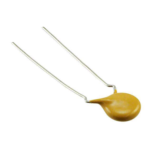
S100K33SL0R63K7R产品简介:
ICGOO电子元器件商城为您提供S100K33SL0R63K7R由Vishay设计生产,在icgoo商城现货销售,并且可以通过原厂、代理商等渠道进行代购。 S100K33SL0R63K7R价格参考。VishayS100K33SL0R63K7R封装/规格:陶瓷电容器, 10pF ±10% 3000V(3kV) 陶瓷电容器 SL 径向,圆片式。您可以下载S100K33SL0R63K7R参考资料、Datasheet数据手册功能说明书,资料中有S100K33SL0R63K7R 详细功能的应用电路图电压和使用方法及教程。
Vishay BC Components 的 S100K33SL0R63K7R 是一款陶瓷电容器,属于多层陶瓷芯片电容(MLCC),具有高稳定性和可靠性。该型号电容器的电容值为33 pF,额定电压为63 V DC,容差为±10%,温度系数符合C0G(NP0)特性,工作温度范围通常为-55°C至+125°C,具备优异的温度稳定性和低损耗。

由于其C0G/NP0材质,S100K33SL0R63K7R特别适用于对电容稳定性要求极高的场景。主要应用包括高频电路、振荡器、滤波器、谐振电路和射频(RF)匹配网络等。广泛用于通信设备(如基站、无线模块)、工业控制系统、医疗电子设备以及汽车电子中的传感器模块和安全系统。

此外,该电容器具有良好的抗老化性能和低失效率,适合在严苛环境或需要长期可靠运行的场合使用。其小型化封装也便于在高密度PCB布局中集成,是高性能模拟和射频设计中的理想选择。
| 参数 | 数值 |
| 产品目录 | |
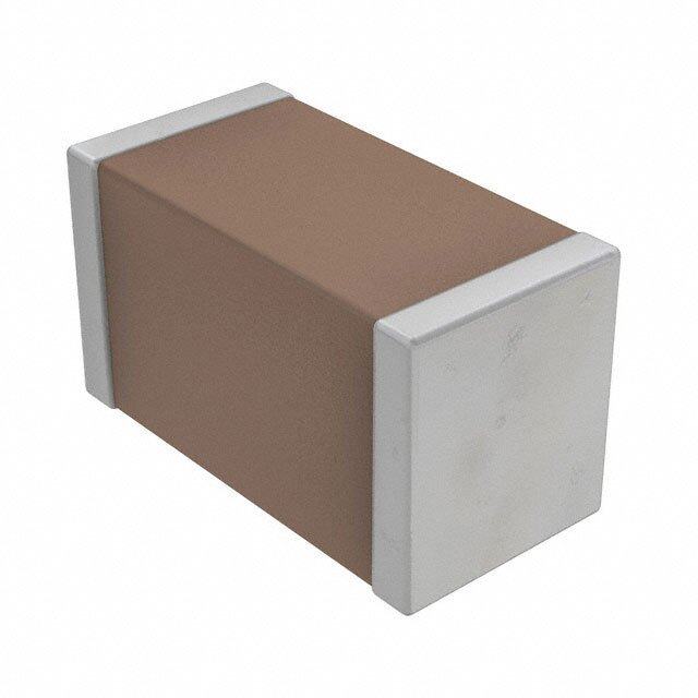
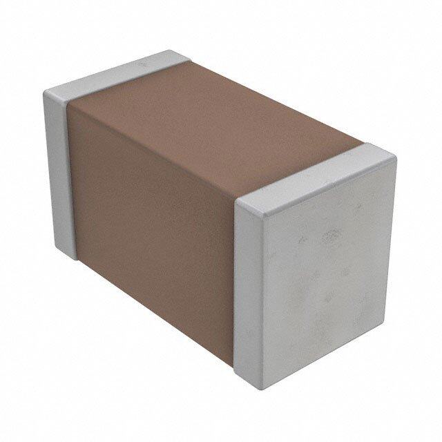
| 描述 | CAP CER 10PF 3KV 10% RADIAL |
| 产品分类 | |
| 品牌 | Vishay BC Components |
| 数据手册 | |
| 产品图片 |
|
| 产品型号 | S100K33SL0R63K7R |
| rohs | 无铅 / 符合限制有害物质指令(RoHS)规范要求 |
| 产品系列 | S |
| 产品目录绘图 |
|
| 其它名称 | 1247PH |
| 包装 | 散装 |
| 厚度(最大值) | - |
| 大小/尺寸 | 0.335" 直径(8.50mm) |
| 安装类型 | 通孔 |
| 容差 | ±10% |
| 封装/外壳 | 径向,圆盘 |
| 工作温度 | -55°C ~ 125°C |
| 应用 | 通用 |
| 引线形式 | 成型引线 - 扭结 |
| 引线间距 | 0.295"(7.50mm) |
| 标准包装 | 1,000 |
| 温度系数 | SL |
| 特性 | - |
| 电压-额定 | 3000V(3kV) |
| 电容 | 10pF |
| 等级 | - |
| 高度-安装(最大值) | 0.492"(12.50mm) |


- 商务部:美国ITC正式对集成电路等产品启动337调查
- 曝三星4nm工艺存在良率问题 高通将骁龙8 Gen1或转产台积电
- 太阳诱电将投资9.5亿元在常州建新厂生产MLCC 预计2023年完工
- 英特尔发布欧洲新工厂建设计划 深化IDM 2.0 战略
- 台积电先进制程称霸业界 有大客户加持明年业绩稳了
- 达到5530亿美元!SIA预计今年全球半导体销售额将创下新高
- 英特尔拟将自动驾驶子公司Mobileye上市 估值或超500亿美元
- 三星加码芯片和SET,合并消费电子和移动部门,撤换高东真等 CEO
- 三星电子宣布重大人事变动 还合并消费电子和移动部门
- 海关总署:前11个月进口集成电路产品价值2.52万亿元 增长14.8%


PDF Datasheet 数据手册内容提取
S Series www.vishay.com Vishay BCcomponents Ceramic Singlelayer DC Disc Capacitors for General Purpose Class 1, Class 2, and Class 3, 1 kV , 2 kV , 3 kV , 6 kV DC DC DC DC FEATURES • High capacitance with small size • High stability • Crimp and straight lead styles • Material categorization: for definitions of compliance please see www.vishay.com/doc?99912 APPLICATIONS • Temperature compensation • Coupling and decoupling • Bypassing QUICK REFERENCE DATA DESCRIPTION VALUE Ceramic Class 1 2 3 Ceramic Dielectric SL0 S3N X7R Y5P X5F Z5U Y5V 1000, 2000, 1000, 2000, 1000, 2000, 1000, 2000, 1000, 2000, Voltage (V ) 6000 1000, 2000 DC 3000, 6000 3000 3000 3000, 6000 3000 Min. Capacitance (pF) 10 47 100 100 100 1000 1000 Max. Capacitance (pF) 470 150 4700 10 000 4700 22 000 33 000 Mounting Radial MARKING CAPACITANCE RANGE Marking indicates capacitance value and tolerance in 10 pF to 33 nF accordance with “EIA 198” and voltage marks. TOLERANCE ON CAPACITANCE OPERATING TEMPERATURE RANGE ± 5 %; ± 10 %; ± 20 %; + 80 % / - 20 % SL0, X7R, X5F: -55 °C to +125 °C Y5P, Z5U, Z5V, Y5V: -30 °C to +125 °C RATED VOLTAGE 1000 V , 2000 V , 3000 V , 6000 V DC DC DC DC TEMPERATURE CHARACTERISTICS Class 1: SL0, S3N TEST VOLTAGE Class 2: X7R, Y5P, X5F, Z5U 200 % of rated voltage Class 3: Y5V INSULATION RESISTANCE AT RATED VOLTAGE SECTIONAL SPECIFICATIONS 10 G min. Climatic category (according to EN 60058-1) DISSIPATION FACTOR Class 1 and 2: 55/125/21 Class 1:0.1 max. when C 30 pF Class 3: 30/85/21 (1 MHz, 1 V where C 1000 pF, and 1 kHz, 1 V where C > 1000 pF) APPROVALS For C < 30 pF: DF = 100/(400 + 20 °C) EIA 198 DF = dissipation factor in %; C = capacitance value in pF IEC 60384-8 Class 2: 2.5 % max. (1 kHz, 1 V) IEC 60384-9 Class 3: 5 % max. (1 kHz, 1 V) DESIGN The capacitors consist of a ceramic disc both sides of which are silver-plated. Connection leads are made of tinned copper wire, having diameters of 0.6 mm or 0.8 mm. The capacitors may be supplied with straight or kinked leads having a lead spacing of 5.0 mm, 7.5 mm and 10.0 mm. Coating is made of epoxy resin in accordance with UL 94 V-0. Revision: 10-Jan-17 1 Document Number: 28515 For technical questions, contact: cdc@vishay.com THIS DOCUMENT IS SUBJECT TO CHANGE WITHOUT NOTICE. THE PRODUCTS DESCRIBED HEREIN AND THIS DOCUMENT ARE SUBJECT TO SPECIFIC DISCLAIMERS, SET FORTH AT www.vishay.com/doc?91000
S Series www.vishay.com Vishay BCcomponents LEAD CONFIGURATION (in millimeters) D D D D T DR SH SH SH * θ K L G G G G L L L F F F F J L K K Note • Lead-spacing 2.5 mm is available for L lead configuration only. MARKING Size 25 Size 29 and above BC TTT TTT XXX XXXt VVVV VVVV Note • Refer to specified part for detail marking. ORDERING CODE INFORMATION S 102 K 29 Y5P N 6 3 J 5 R 1 2 3 4 5 6 7 8 9 10 11 12 13 14 15 16 Product Capacitance Capacitance Size T.C. Rated Lead Packaging / Lead Lead RoHS- Type (pF) Tolerance Code Code Voltage Diameter Lead Length Style Spacing Compliant S series The first two J = ± 5 % Please Please N = 1000 V 6 = 0.60 mm 3 = bulk Please 5 = 5.0 mm R = RoHS- DC digits are the K = ± 10 % refer to refer to P = 2000 VDC ± 0.05 mm T = tape refer to 6 = 6.4 mm compliant significant M = ± 20 % relevant relevant R = 3000 VDC 8 = 0.80 mm and reel relevant 7 = 7.5 mm G = RoHS- figures of Z = + 80 % / datasheet datasheetU = 6000 VDC ± 0.05 mm U = ammo datasheet0 = 10.0 mm compliant capacitance and - 20 % and the last digit is a multiplier as halogen-free follows: 0 = * 1 1 = * 10 2 = * 100 3 = * 1000 Revision: 10-Jan-17 2 Document Number: 28515 For technical questions, contact: cdc@vishay.com THIS DOCUMENT IS SUBJECT TO CHANGE WITHOUT NOTICE. THE PRODUCTS DESCRIBED HEREIN AND THIS DOCUMENT ARE SUBJECT TO SPECIFIC DISCLAIMERS, SET FORTH AT www.vishay.com/doc?91000
S Series www.vishay.com Vishay BCcomponents ORDERING CODES DIELECTRIC SL0 (1000 V / 2000 V ) DC DC 1000 V 2000 V DC DC CAP. (pF) ORDERING CODE DIAMETER THICKNESS ORDERING CODE DIAMETER THICKNESS (mm max.) (mm max.) (mm max.) (mm max.) 10 S100#25SL0N6###R 6.5 4 S100#25SL0P6###R 6.5 4.5 12 S120#25SL0N6###R 6.5 4 S120#25SL0P6###R 6.5 4.5 15 S150#25SL0N6###R 6.5 4 S150#25SL0P6###R 6.5 4.5 18 S180#25SL0N6###R 6.5 4 S180#25SL0P6###R 6.5 4.5 22 S220#25SL0N6###R 6.5 4 S220#25SL0P6###R 6.5 4.5 27 S270#25SL0N6###R 6.5 4 S270#25SL0P6###R 6.5 4.5 33 S330#25SL0N6###R 6.5 4 S330#29SL0P6###R 7.5 4.5 39 S390#25SL0N6###R 6.5 4 S390#29SL0P6###R 7.5 4.5 47 S470#25SL0N6###R 6.5 4 S470#29SL0P6###R 7.5 4.5 56 S560#29SL0N6###R 7.5 4 S560#29SL0P6###R 7.5 4.5 68 S680#29SL0N6###R 7.5 4 S680#33SL0P6###R 8.5 4.5 82 S820#29SL0N6###R 7.5 4 S820#33SL0P6###R 8.5 4.5 100 S101#29SL0N6###R 7.5 4 S101#39SL0P6###R 10 4.5 120 S121#33SL0N6###R 8.5 4 S121#39SL0P6###R 10 4.5 150 S151#33SL0N6###R 8.5 4 S151#43SL0P6###R 11 4.5 180 S181#39SL0N6###R 10 4 / / / 220 S221#39SL0N6###R 10 4 / / / DIELECTRIC SL0 (3000 V / 6000 V ) DC DC 3000 V 6000 V (1) DC DC CAP. (pF) ORDERING CODE DIAMETER THICKNESS ORDERING CODE DIAMETER THICKNESS (mm max.) (mm max.) (mm max.) (mm max.) 10 S100#33SL0R6###R 8.5 5.5 S100#39SL0U83L0R 10 8 12 S120#33SL0R6###R 8.5 5.5 S120#39SL0U83L0R 10 8 15 S150#33SL0R6###R 8.5 5.5 S150#43SL0U83L0R 11 8 18 S180#33SL0R6###R 8.5 5.5 S180#43SL0U83L0R 11 8 22 S220#33SL0R6###R 8.5 5.5 S220#43SL0U83L0R 11 8 27 S270#33SL0R6###R 8.5 5.5 S270#47SL0U83L0R 12 8 33 S330#33SL0R6###R 8.5 5.5 S330#53SL0U83L0R 13.5 8 39 S390#33SL0R6###R 8.5 5.5 / / / 47 S470#33SL0R6###R 8.5 5.5 / / / 56 S560#39SL0R6###R 10 5.5 / / / 68 S680#39SL0R6###R 10 5.5 / / / Notes • Lead diameter is 0.6 mm • # 5th digit is capacitance tolerance code: ± 5 % = J; ± 10 % = K • # 13th digit is packaging code: bulk = 3; reel = T; ammo = U • # 14th digit is lead style code: L; J; K (J is valid for 1 kV only) • # 15th digit is lead spacing code: 5.0 mm = 5; 6.4 mm = 6; 7.5 mm = 7; 10.0 mm = 0 (1) For 6000 V part, only straight lead configuration (0.8 mm lead diameter) and bulk packaging are available Revision: 10-Jan-17 3 Document Number: 28515 For technical questions, contact: cdc@vishay.com THIS DOCUMENT IS SUBJECT TO CHANGE WITHOUT NOTICE. THE PRODUCTS DESCRIBED HEREIN AND THIS DOCUMENT ARE SUBJECT TO SPECIFIC DISCLAIMERS, SET FORTH AT www.vishay.com/doc?91000
S Series www.vishay.com Vishay BCcomponents DIELECTRIC Z5U (1000 V / 2000 V ) DC DC 1000 V 2000 V DC DC CAP. (pF) DIAMETER THICKNESS DIAMETER THICKNESS ORDERING CODE ORDERING CODE (mm max.) (mm max.) (mm max.) (mm max.) 1000 S102#25Z5UN6###R 6.5 4 S102#29Z5UP6###R 7.5 4.5 1500 S152#29Z5UN6###R 7.5 4 S152#29Z5UP6###R 7.5 4.5 2200 S222#29Z5UN6###R 7.5 4 S222#33Z5UP6###R 8.5 4.5 3300 S332#33Z5UN6###R 8.5 4 S332#43Z5UP6###R 11.0 4.5 4700 S472#39Z5UN6###R 10 4 S472#47Z5UP6###R 12.0 4.5 6800 S682#43Z5UN6###R 11 4 S682#53Z5UP63K7R 13.5 4.5 10 000 S103#47Z5UN6###R 12 4 S103#69Z5UP63K7R 17.5 4.5 15 000 S153#59Z5UN63J7R 15 4 / / / 22 000 S223#75Z5UN83J0R 19 4 / / / DIELECTRIC Z5U (3000 V / 6000 V ) DC DC 3000 V 6000 V DC DC CAP. (pF) DIAMETER THICKNESS DIAMETER THICKNESS ORDERING CODE ORDERING CODE (mm max.) (mm max.) (mm max.) (mm max.) 220 / / / S221#39Z5UU83L0R 10 8 330 / / / S331#43Z5UU83L0R 11 8 470 S471#33Z5UR6###R 8.5 5.5 S471#47Z5UU83L0R 12 8 1000 S102#33Z5UR6###R 8.5 5.5 S102#59Z5UU83L0R 15 8 1500 S152#39Z5UR6###R 10.0 5.5 S152#69Z5UU83L0R 17.5 8 2200 S222#43Z5UR6###R 11.0 5.5 S222M75Z5UU83L0R 19 8 3300 S332#53Z5UR63K7R 13.5 5.5 / / / 4700 S472#69Z5UR63K7R 17.5 5.5 / / / Notes • Lead diameter is 0.6 mm • # 5th digit is capacitance tolerance code: ± 20 % = M; + 80 % / - 20 % = Z • # 13th digit is packaging code: bulk = 3; reel = T; ammo = U • # 14th digit is lead style code: L; J; K (J is valid for 1 kV only) • # 15th digit is lead spacing code: 5.0 mm = 5; 6.4 mm = 6; 7.5 mm = 7; 10.0 mm = 0 Revision: 10-Jan-17 4 Document Number: 28515 For technical questions, contact: cdc@vishay.com THIS DOCUMENT IS SUBJECT TO CHANGE WITHOUT NOTICE. THE PRODUCTS DESCRIBED HEREIN AND THIS DOCUMENT ARE SUBJECT TO SPECIFIC DISCLAIMERS, SET FORTH AT www.vishay.com/doc?91000
S Series www.vishay.com Vishay BCcomponents DIELECTRIC Y5P (1000 V / 2000 V ) DC DC 1000 V 2000 V DC DC CAP. (pF) ORDERING CODE DIAMETER THICKNESS ORDERING CODE DIAMETER THICKNESS (mm max.) (mm max.) (mm max.) (mm max.) 100 S101#25Y5PN6###R 6.5 4.0 S101#25Y5PP6###R 6.5 4.5 120 S121#25Y5PN6###R 6.5 4.0 S121#25Y5PP6###R 6.5 4.5 150 S151#25Y5PN6###R 6.5 4.0 S151#25Y5PP6###R 6.5 4.5 180 S181#25Y5PN6###R 6.5 4.0 S181#25Y5PP6###R 6.5 4.5 220 S221#25Y5PN6###R 6.5 4.0 S221#25Y5PP6###R 6.5 4.5 270 S271#25Y5PN6###R 6.5 4.0 S271#25Y5PP6###R 6.5 4.5 330 S331#25Y5PN6###R 6.5 4.0 S331#25Y5PP6###R 6.5 4.5 470 S471#25Y5PN6###R 6.5 4.0 S471#29Y5PP6###R 7.5 4.5 560 S561#29Y5PN6###R 7.5 4.0 S561#29Y5PP6###R 7.5 4.5 680 S681#29Y5PN6###R 7.5 4.0 S681#29Y5PP6###R 7.5 4.5 820 S821#29Y5PN7###R 7.5 4.0 S821#33Y5PP6###R 8.5 4.5 1000 S102#29Y5PN6###R 7.5 4.0 S102#33Y5PP6###R 8.5 4.5 1500 S152#33Y5PN6###R 8.5 4.0 S152#39Y5PP6###R 10.0 4.5 1800 S182#33Y5PN6###R 8.5 4.0 S182#43Y5PP6###R 11.0 4.5 2200 S222#39Y5PN6###R 10.0 4.0 S222#43Y5PP6###R 11.0 4.5 3300 S332#43Y5PN6###R 11.0 4.0 S332#53Y5PP6###R 13.5 4.5 4700 S472#53Y5PN6###R 13.5 4.0 S472#69Y5PP63K7R 17.5 4.5 6800 S682#59Y5PN63J7R 15.0 4.0 / / / 10 000 S103#75Y5PN83J0R 19.0 4.0 / / / DIELECTRIC Y5P (3000 V ) DC 3000 V DC CAP. (pF) ORDERING CODE DIAMETER THICKNESS (mm max.) (mm max.) 100 S101#33Y5PR6###R 8.5 5.5 120 S121#33Y5PR6###R 8.5 5.5 150 S151#33Y5PR6###R 8.5 5.5 180 S181#33Y5PR6###R 8.5 5.5 220 S221#33Y5PR6###R 8.5 5.5 270 S271#33Y5PR6###R 8.5 5.5 330 S331#33Y5PR6###R 8.5 5.5 470 S471#33Y5PR6###R 8.5 5.5 560 S561#39Y5PR6###R 10.0 5.5 680 S681#39Y5PR6###R 10.0 5.5 820 S821#39Y5PR6###R 10.0 5.5 1000 S102#43Y5PR6###R 11.0 5.5 1500 S152#47Y5PR6###R 12.0 5.5 1800 S182#47Y5PR6###R 12.0 5.5 2200 S222#59Y5PR63K7R 15.0 5.5 3300 S332#75Y5PR83K0R 19.0 5.5 Notes • Lead diameter is 0.6 mm • # 5th digit is capacitance tolerance code: ± 5 % = J; ± 10 % = K • # 13th digit is packaging code: bulk = 3; reel = T; ammo = U • # 14th digit is lead style code: L; J; K (J is valid for 1 kV only) • # 15th digit is lead spacing code: 5.0 mm = 5; 6.4 mm = 6; 7.5 mm = 7; 10.0 mm = 0 Revision: 10-Jan-17 5 Document Number: 28515 For technical questions, contact: cdc@vishay.com THIS DOCUMENT IS SUBJECT TO CHANGE WITHOUT NOTICE. THE PRODUCTS DESCRIBED HEREIN AND THIS DOCUMENT ARE SUBJECT TO SPECIFIC DISCLAIMERS, SET FORTH AT www.vishay.com/doc?91000
S Series www.vishay.com Vishay BCcomponents DIELECTRIC X7R (1000 V / 2000 V ) DC DC 1000 V 2000 V CAP. DC DC DIAMETER THICKNESS DIAMETER THICKNESS (pF) ORDERING CODE ORDERING CODE (mm max.) (mm max.) (mm max.) (mm max.) 100 S101#25X7RN6###R 6.5 4.0 S101#25X7RP6###R 6.5 4.5 120 S121#25X7RN6###R 6.5 4.0 S121#25X7RP6###R 6.5 4.5 150 S151#25X7RN6###R 6.5 4.0 S151#25X7RP6###R 6.5 4.5 180 S181#25X7RN6###R 6.5 4.0 S181#25X7RP6###R 6.5 4.5 220 S221#25X7RN6###R 6.5 4.0 S221#25X7RP6###R 6.5 4.5 270 S271#25X7RN6###R 6.5 4.0 S271#25X7RP6###R 6.5 4.5 330 S331#25X7RN6###R 6.5 4.0 S331#25X7RP6###R 6.5 4.5 470 S471#29X7RN6###R 7.5 4.0 S471#29X7RP6###R 7.5 4.5 560 S561#29X7RN6###R 7.5 4.0 S561#33X7RP6###R 8.5 4.5 680 S681#29X7RN6###R 7.5 4.0 S681#33X7RP6###R 8.5 4.5 820 S821#29X7RN7###R 7.5 4.0 S821#39X7RP6###R 10.0 4.5 1000 S102#33X7RN6###R 8.5 4.0 S102#39X7RP6###R 10.0 4.5 1500 S152#39X7RN6###R 10.0 4.0 S152#43X7RP6###R 11.0 4.5 1800 S182#43X7RN6###R 11.0 4.0 S182#47X7RP6###R 12.0 4.5 2200 S222#43X7RN6###R 11.0 4.0 S222#53X7RP6###R 13.0 4.5 3300 S332#47X7RN6###R 12.0 4.0 S332#59X7RP63K7R 15.0 4.5 4700 S472#59X7RN63J7R 15.0 4.0 / / / DIELECTRIC X7R (3000 V ) DC 3000 V CAP. DC DIAMETER THICKNESS (pF) ORDERING CODE (mm max.) (mm max.) 100 S101#33X7RR6###R 8.5 5.5 120 S121#33X7RR6###R 8.5 5.5 150 S151#33X7RR6###R 8.5 5.5 180 S181#33X7RR6###R 8.5 5.5 220 S221#33X7RR6###R 8.5 5.5 270 S271#33X7RR6###R 8.5 5.5 330 S331#33X7RR6###R 8.5 5.5 470 S471#33X7RR6###R 8.5 5.5 560 S561#39X7RR6###R 10.0 5.5 680 S681#39X7RR6###R 10.0 5.5 820 S821#43X7RR6###R 11.0 5.5 1000 S102#43X7RR6###R 11.0 5.5 1500 S152#53X7RR6###R 13.0 5.5 1800 S182#59X7RR63K7R 15.0 5.5 2200 S222#59X7RR63K7R 15.0 5.5 Notes • Lead diameter is 0.6 mm • # 5th digit is capacitance tolerance code: ± 5 % = J; ± 10 % = K • # 13th digit is packaging code: bulk = 3; reel = T; ammo = U • # 14th digit is lead style code: L; J; K (J is valid for 1 kV only) • # 15th digit is lead spacing code: 5.0 mm = 5; 6.4 mm = 6; 7.5 mm = 7; 10.0 mm = 0 Revision: 10-Jan-17 6 Document Number: 28515 For technical questions, contact: cdc@vishay.com THIS DOCUMENT IS SUBJECT TO CHANGE WITHOUT NOTICE. THE PRODUCTS DESCRIBED HEREIN AND THIS DOCUMENT ARE SUBJECT TO SPECIFIC DISCLAIMERS, SET FORTH AT www.vishay.com/doc?91000
S Series www.vishay.com Vishay BCcomponents DIELECTRIC Y5V (1000 V / 2000 V ) DC DC 1000 V 2000 V DC DC CAP. (pF) DIAMETER THICKNESS DIAMETER THICKNESS ORDERING CODE ORDERING CODE (mm max.) (mm max.) (mm max.) (mm max.) 1000 S102Z25Y5VN6###R 6.5 4.0 S102Z29Y5VP6###R 7.5 4.5 1500 S152Z25Y5VN6###R 6.5 4.0 S152Z29Y5VP6###R 7.5 4.5 2200 S222Z29Y5VN6###R 7.5 4.0 S222Z33Y5VP6###R 8.5 4.5 3300 S332Z29Y5VN6###R 7.5 4.0 S332Z39Y5VP6###R 10.0 4.5 4700 S472Z33Y5VN6###R 8.5 4.0 S472Z43Y5VP6###R 11.0 4.5 6800 S682Z39Y5VN6###R 10.0 4.0 S682Z47Y5VP6###R 12.0 4.5 10 000 S103Z43Y5VN6###R 11.0 4.0 S103Z59Y5VP6###R 15.0 4.5 15 000 S153Z53Y5VN63J7R 13.5 4.0 / / / 22 000 S223Z59Y5VN63J7R 15.0 4.0 / / / 33 000 S333Z75Y5VN83J0R 19.0 4.0 / / / DIELECTRIC Y5V (3000 V ) DC 3000 V DC CAP. (pF) DIAMETER THICKNESS ORDERING CODE (mm max.) (mm max.) 1000 S102Z33Y5VR6###R 8.5 5.5 1500 S152Z33Y5VR6###R 8.5 5.5 2200 S222Z39Y5VR6###R 10.0 5.5 3300 S332Z43Y5VR6###R 11.0 5.5 4700 S472Z47Y5VR6###R 12.0 5.5 6800 S682Z59Y5VR6###R 15.0 5.5 Notes • Lead diameter is 0.6 mm • # 5th digit is capacitance tolerance code: ± 5 % = J; ± 10 % = K • # 13th digit is packaging code: bulk = 3; reel = T; ammo = U • # 14th digit is lead style code: L; J; K (J is valid for 1 kV only) • # 15th digit is lead spacing code: 5.0 mm = 5; 6.4 mm = 6; 7.5 mm = 7; 10.0 mm = 0 Revision: 10-Jan-17 7 Document Number: 28515 For technical questions, contact: cdc@vishay.com THIS DOCUMENT IS SUBJECT TO CHANGE WITHOUT NOTICE. THE PRODUCTS DESCRIBED HEREIN AND THIS DOCUMENT ARE SUBJECT TO SPECIFIC DISCLAIMERS, SET FORTH AT www.vishay.com/doc?91000
S Series www.vishay.com Vishay BCcomponents DIELECTRIC X5F (1000 V / 2000 V ) DC DC 1000 V 2000 V CAP. DC DC DIAMETER THICKNESS DIAMETER THICKNESS (pF) ORDERING CODE ORDERING CODE (mm max.) (mm max.) (mm max.) (mm max.) 100 S101#25X5FN6###R 6.5 4.0 S101#25X5FP6###R 6.5 4.5 120 S121#25X5FN6###R 6.5 4.0 S121#25X5FP6###R 6.5 4.5 150 S151#25X5FN6###R 6.5 4.0 S151#25X5FP6###R 6.5 4.5 180 S181#25X5FN6###R 6.5 4.0 S181#25X5FP6###R 6.5 4.5 220 S221#25X5FN6###R 6.5 4.0 S221#25X5FP6###R 6.5 4.5 270 S271#25X5FN6###R 6.5 4.0 S271#29X5FP6###R 7.5 4.5 330 S331#25X5FN6###R 6.5 4.0 S331#29X5FP6###R 7.5 4.5 390 S391#25X5FN6###R 6.5 4.0 S391#31X5FP6###R 8.0 4.5 470 S471#25X5FN6###R 6.5 4.0 S471#31X5FP6###R 8.0 4.5 560 S561#29X5FN6###R 7.5 4.0 S561#33X5FP6###R 8.5 4.5 680 S681#29X5FN6###R 7.5 4.0 S681#39X5FP6###R 10.0 4.5 820 S821#29X5FN7###R 7.5 4.0 S821#43X5FP6###R 11.0 4.5 1000 S102#29X5FN6###R 7.5 4.0 S102#43X5FP6###R 11.0 4.5 1500 S152#39X5FN6###R 10.0 4.0 S152#47X5FP6###R 12.0 4.5 1800 S182#43X5FN6###R 11.0 4.0 S182#53X5FP63K7R 13.5 4.5 2200 S222#43X5FN6###R 11.0 4.0 S222#59X5FP63K7R 15.0 4.5 3300 S332#53X5FN63J7R 12.0 4.0 S332#65X5FP63K7R 16.5 4.5 4700 S472#63X5FN63J7R 15.0 4.0 / / / Notes • Lead diameter is 0.6 mm • # 5th digit is capacitance tolerance code: ± 5 % = J; ± 10 % = K • # 13th digit is packaging code: bulk = 3; reel = T; ammo = U • # 14th digit is lead style code: L; J; K (J is valid for 1 kV only) • # 15th digit is lead spacing code: 5.0 mm = 5; 6.4 mm = 6; 7.5 mm = 7; 10.0 mm = 0 DIELECTRIC S3N (6000 V ) DC 6000 V CAP. DC DIAMETER THICKNESS (pF) ORDERING CODE (mm max.) (mm max.) 47 S470M43S3NU83L0R 11.0 8.0 68 S680M53S3NU83L0R 13.5 8.0 100 S101M59S3NU83L0R 15.0 8.0 150 S151M59S3NU83L0R 15.0 8.0 Notes • Lead diameter is 0.6 mm • # 5th digit is capacitance tolerance code: ± 5 % = J; ± 10 % = K • # 13th digit is packaging code: bulk = 3; reel = T; ammo = U • # 14th digit is lead style code: L; J; K (J is valid for 1 kV only) • # 15th digit is lead spacing code: 5.0 mm = 5; 6.4 mm = 6; 7.5 mm = 7; 10.0 mm = 0 TAPING AND PACKAGING LABELLING For example: Each reel is provided with a label showing the following details: manufacturer, D style, capacitance, tolerance, batch number, quantity of components, rated voltage, dielectric. On special request other designations can be shown. Revision: 10-Jan-17 8 Document Number: 28515 For technical questions, contact: cdc@vishay.com THIS DOCUMENT IS SUBJECT TO CHANGE WITHOUT NOTICE. THE PRODUCTS DESCRIBED HEREIN AND THIS DOCUMENT ARE SUBJECT TO SPECIFIC DISCLAIMERS, SET FORTH AT www.vishay.com/doc?91000
S Series www.vishay.com Vishay BCcomponents PACKAGING QUANTITIES AND BOX DIMENSIONS LEAD SPACING RATED SMALLEST PACKAGING BOX DIMENSIONS PACKAGING SIZE CODE (mm) VOLTAGE QUANTITY (SPQ) L x W x H (mm) 2000 2000 6.4 47 3000 1000 Tape on reel 370 x 370 x 60 7.5 all 1000 59 all all 500 < 2000 2000 6.4 335 x 240 x 50 47 2000 1500 Ammopack 7.5 all 1500 335 x 290 x 50 > 47 > 6.4 all 1000 < 49 all < 6000 1000 49 to 75 all < 6000 500 Bulk (1) > 75 all < 6000 250 245 x 120 x 65 49 all 6000 500 > 49 all 6000 250 Note (1) SPQ contains one or a multiple of poly-bags, 1000 units per bag. CAPACITORS ON TAPE D P P 2 ΔP ΔP Δh H 1 W 2 H0 t1 detail A t W 1 W0W A e Direction of unreeling Ø d P1 PF D0 0 PARAMETER SYMBOL DIMENSIONS (mm) Body diameter D 11.0 max. 11.0 max. 14.0 max. Lead diameter d 0.6 ± 0.05 0.6 ± 0.05 0.6 ± 0.05 Pitch of component p 12.7 ± 1.0 12.7 ± 1.0 15.0 ± 1.0 Pitch of sprocket hole P 12.7 ± 0.3 12.7 ± 0.3 15.0 ± 0.3 0 Distance, hole center to lead P 5.1 ± 0.7 3.85 ± 0.7 3.75 ± 0.7 1 Distance, hole to center of component P 6.35 ± 1.3 6.35 ± 1.3 7.5 ± 1.5 2 Lead spacing F 2.5 + 0.60 / - 0.40 5.0 + 0.60 / - 0.40 7.5 + 0.6 / - 0.4 Average deviation across tape h ± 1.0 max. ± 1.0 max. ± 1.0 max. Average deviation in direction of reeling P ± 1.0 max. ± 1.0 max. ± 1.0 max. Carrier tape width W 18.0 + 1.0 / - 0.5 18.0 + 1.0 / - 0.5 18.0 + 1.0 / - 0.5 Hold-down tape width W 5.0 min. 5.0 min. 5.0 min. 0 Position of sprocket hole W 9.0 + 0.75 / - 0.5 9.0 + 0.75 / - 0.5 9.0 + 0.75 / - 0.5 1 Distance of hold-down tape W 3.0 max. 3.0 max. 3.0 max. 2 Maximum component height H 32 max. 32 max. 40 max. 1 Height to seating plane (for kinked leads) H 16.0 ± 0.5 16.0 ± 0.5 16.0 ± 0.5 0 Height to seating plane (for straight leads) H 20.0 ± 0.5 20.0 ± 0.5 20.0 ± 0.5 0 Length of cut leads L 11.0 max. 11.0 max. 11.0 max. Length of lead protrusion e 1.0 max. 1.0 max. 1.0 max. Diameter of sprocket hole D 4.0 ± 0.2 4.0 ± 0.2 4.0 ± 0.2 0 Total tape thickness t 0.9 max. 0.9 max. 0.9 max. Maximum thickness of taping and wires t 1.5 max. 1.5 max. 1.5 max. 1 Revision: 10-Jan-17 9 Document Number: 28515 For technical questions, contact: cdc@vishay.com THIS DOCUMENT IS SUBJECT TO CHANGE WITHOUT NOTICE. THE PRODUCTS DESCRIBED HEREIN AND THIS DOCUMENT ARE SUBJECT TO SPECIFIC DISCLAIMERS, SET FORTH AT www.vishay.com/doc?91000
S Series www.vishay.com Vishay BCcomponents P ΔP ΔPP2 Δh T Δh D H F 1 Ø d L W 2 H 0 W 1 W W 0 A e P0 P1 F D0 t t1 detail A DIMENSIONS OF TAPE DIMENSIONS SYMBOL PARAMETER (mm) D (1) Body diameter 19.0 max. d Lead diameter 0.6 ± 0.05 P Pitch of component 25.4 ± 1 P (2) Pitch of sprocket hole 12.7 ± 0.3 0 P (3) Distance, hole center to lead 7.7 or 6.4 ± 1.0 1 P (3) Distance, hole to center of component 12.7 ± 1.5 2 F Lead spacing 10.0 or 12.5 + 0.6 / - 0.4 h Average deviation across tape ± 1.0 max. P Average deviation in direction of reeling ± 1.0 max. W Carrier tape width 18.0 + 1 / - 0.5 W Hold-down tape width 5.0 min. 0 W Position of sprocket hole 9.0 + 0.75 / - 0.5 1 W Distance of hold-down tape 3.0 max. 2 H Maximum component height 40.0 1 H Height to seating plane (for kinked leads) 16.0 ± 0.5 0 H Height to seating plane (for straight leads) 20.0 ± 0.5 0 L Length of cut leads 11.0 max. l Length of lead protrusion 1.0 max. D Diameter of sprocket hole 4.0 ± 0.2 0 t Total tape thickness 0.9 max. Notes (1) See Ordering Information table (2) Cumulative pitch error: ± 1 mm / 20 pitches (3) Obliquity maximum 3° Revision: 10-Jan-17 10 Document Number: 28515 For technical questions, contact: cdc@vishay.com THIS DOCUMENT IS SUBJECT TO CHANGE WITHOUT NOTICE. THE PRODUCTS DESCRIBED HEREIN AND THIS DOCUMENT ARE SUBJECT TO SPECIFIC DISCLAIMERS, SET FORTH AT www.vishay.com/doc?91000
Legal Disclaimer Notice www.vishay.com Vishay Disclaimer ALL PRODUCT, PRODUCT SPECIFICATIONS AND DATA ARE SUBJECT TO CHANGE WITHOUT NOTICE TO IMPROV E RELIABILITY, FUNCTION OR DESIGN OR OTHERWISE. Vishay Intertechnology, Inc., its affiliates, agents, and employees, and all persons acting on its or their behalf (collectively, “Vishay”), disclaim any and all liability for any errors, inaccuracies or incompleteness contained in any datasheet or in any other disclosure relating to any product. Vishay makes no warranty, representation or guarantee regarding the suitability of the products for any particular purpose o r the continuing production of any product. To the maximum extent permitted by applicable law, Vishay disclaims (i) any and all liability arising out of the application or use of any product, (ii) any and all liability, including without limitation special, consequential or incidental damages, and (iii) any and all implied warranties, including warranties of fitness for particular purpose, non-infringement and merchantability. Statements regarding the suitability of products for certain types of applications are based on Vishay’s knowledge of typical requirements that are often placed on Vishay products in generic applications. Such statements are not binding statements about the suitability of products for a particular application. It is the customer’s responsibility to validate that a particular product with the properties described in the product specification is suitable for use in a particular application. Parameters provided in datasheets and / or specifications may vary in different applications and performance may vary over time. All operating parameters, including typical parameters, must be validated for each customer application by the customer’s technical experts. Product specifications do not expand or otherwise modify Vishay’s terms and conditions of purchase, including but not limited to the warranty expressed therein. Except as expressly indicated in writing, Vishay products are not designed for use in medical, life-saving, or life-sustainin g applications or for any other application in which the failure of the Vishay product could result in personal injury or death. Customers using or selling Vishay products not expressly indicated for use in such applications do so at their own risk . Please contact authorized Vishay personnel to obtain written terms and conditions regarding products designed for such applications. No license, express or implied, by estoppel or otherwise, to any intellectual property rights is granted by this documen t or by any conduct of Vishay. Product names and markings noted herein may be trademarks of their respective owners. © 2019 VISHAY INTERTECHNOLOGY, INC. ALL RIGHTS RESERVED Revision: 01-Jan-2019 1 Document Number: 91000
Mouser Electronics Authorized Distributor Click to View Pricing, Inventory, Delivery & Lifecycle Information: V ishay: S820K29SLON6TK6 S120K25SLON63L6 S220K25SL0N63L6 S103K75Y5PN83K0 S152M29Z5UN63L6 S102M59Z5UU83L0 S102K29X5FN63L6R S101K29S3NN6TJ5 S101K29S3NN6TJ6 S479C25C0GN65J6 S100K25SL0N63L6 S101K29S3NN63L6R S101K29S3NN6TJ5R S101K29S3NN6TJ6R S102K29Y5PN6TK6R S102M33Z5UR63K7R S102M33Z5UR63L6R S103K75Y5PN83J0 S103K75Y5PN83J0R S103K75Y5PN83K0R S103M47Z5UN63L0R S103M47Z5UN63L6R S103M69Z5UP63K7R S121K29S3NN63L6R S151K29S3NN6TK6 S151K29S3NN6TK6R S151K33SL0N63L6 S151K33SL0N63L6R S151K33Y5PR63K7R S152K33Y5PN63L6R S152M29Z5UN63L6R S181K33SL0N63L6 S200K25SL0N63L6R S201K33S3NN63L6R S202M29Z5UN63L6R S220K25SL0N63L6R S220K25SL0N6TJ6R S221K25X5FN63L6R S221K25Y5PN6TK5R S221K25Y5PN6UL5R S222M29Z5UN63L6R S222M29Z5UN6TL6 S222M29Z5UN6TL6R S250K25SL0N63L6R S270K25SL0N63L6R S271K25X5FN63L6R S271K43SL0N6TK5R S300K25SL0N63L6R S301K25X5FN63L6R S302M33Z5UN63L6R S330K25SL0N63L6R S330M33S3NR6TK6R S331K25X5FN63L6R S361K25X5FN63L6R S390K25SL0N63L6R S391K25X5FN63L6R S392M33Z5UN63L6 S392M33Z5UN63L6R S470K25SL0N63L6 S470K25SL0N63L6R S471K25X5FN6TJ6R S471K25Y5PN63L6R S471K25Y5PN6TL6R S471K29X5FN63L6 S472M39Z5UN63L6R S472M69Z5UR83L0R S501K29X5FN63L6 S501K29X5FN63L6R S501M25Z5UN63L6R S502M39Z5UN63L6R S502M75Z5UR83L0R S681K29X7RN63L6 S681K29X7RN63L6R S682M43Z5UN63L0R S750K25S3NN63L6R S750K25S3NN6TJ5R S751K29Y5PN63L6 S751K29Y5PN63L6R S821K29X7RN63L6R S680K25S3NN63L6R S820K25S3NN63L6R S181K29S3NN63L6R S102K29X5FN6TJ5R S503Z69Z5UL63L0R S471K29X7RP63K5R S102K29Y5PN6TJ5R S471K25X5FN63L6R S101K29SL0N6TK5R S332K47X7RN63J7R S101K29S3NN63L6 S221K25Y5PN6TK5 S150K25SLON63L6 S103K84X7RN8BK0 S271K25X5FN63L6 S103M47Z5UN63L6 S103M47Z5UN63L0 S100K25SL0N63L6R S102M33Z5UR63L6 S250K25SL0N63L6 S202M29Z5UN63L6