
 Datasheet下载
- 型号: RWM04104R70JR15E1
- 制造商: Vishay
- 库位|库存: xxxx|xxxx
- 要求:
| 数量阶梯 | 香港交货 | 国内含税 |
| +xxxx | $xxxx | ¥xxxx |
查看当月历史价格
查看今年历史价格
RWM04104R70JR15E1产品简介:
ICGOO电子元器件商城为您提供RWM04104R70JR15E1由Vishay设计生产,在icgoo商城现货销售,并且可以通过原厂、代理商等渠道进行代购。 RWM04104R70JR15E1价格参考。VishayRWM04104R70JR15E1封装/规格:通孔电阻器, 4.7 Ohms ±5% 3W 轴向 通孔电阻器 耐燃,安全 绕线。您可以下载RWM04104R70JR15E1参考资料、Datasheet数据手册功能说明书,资料中有RWM04104R70JR15E1 详细功能的应用电路图电压和使用方法及教程。
该描述存在根本性错误:RWM04104R70JR15E1 并非电阻器,更不是通孔式电阻器,而是 Vishay Semiconductor Diodes Division(现属Vishay Intertechnology旗下)生产的一款 表面贴装(SMD)金属氧化物压敏电阻(MOV),属于 过压保护器件,而非电阻器。

其型号解析:
- “RWM” 是 Vishay MOV 系列标识;
- “04” 表示直径约 4.3 mm 的圆片型封装(但实际为 SMD 封装,非通孔);
- “10” 指最大连续工作电压 AC 10 V(典型值),实际为 10 VAC / 14 VDC;
- “4R70” 表示标称压敏电压为 4.7 V ±10%(即 Vₙ = 4.7 V);
- “J” 表示电压容差 ±5%,"R15" 指最大峰值浪涌电流 15 A(8/20 μs 波形);
- “E1” 为包装与版本代码。

应用场景(中文,≤500字):
该器件专用于 低电压直流电路的瞬态过压防护,典型应用包括:USB 接口(如 USB 2.0 数据线或电源端)、便携式电子设备(蓝牙耳机、TWS 充电盒、智能手表)的 ESD 和 EFT 防护;电池管理系统(BMS)中对单节锂电(3.0–4.2 V)的钳位保护;IoT 传感器节点、MCU GPIO 引脚、I²C/SPI 总线等低压信号线的静电放电(IEC 61000-4-2 Level 4,±8 kV 接触放电)及快速脉冲群(EFT)抑制。因其超低钳位电压(<12 V @ 1 A)和纳秒级响应,可有效防止低压逻辑芯片(如 3.3 V 或 1.8 V MCU、LDO、USB PHY)因瞬态电压击穿而损坏。需注意:它不适用于持续过压或大能量浪涌场景,且为 SMD 封装(0402 或类似尺寸),非通孔式(THT)安装,不可用于传统插件电阻应用场景。
| 参数 | 数值 |
| 产品目录 | |
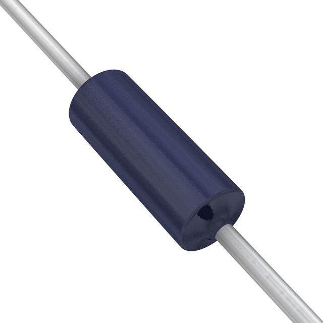
| 描述 | RES WIREWOUND 4.7 OHM 3W线绕电阻器 - 透孔 3watt 4.7ohm 5% |
| 产品分类 | |
| 品牌 | Vishay / SferniceVishay Sfernice |
| 产品手册 | |
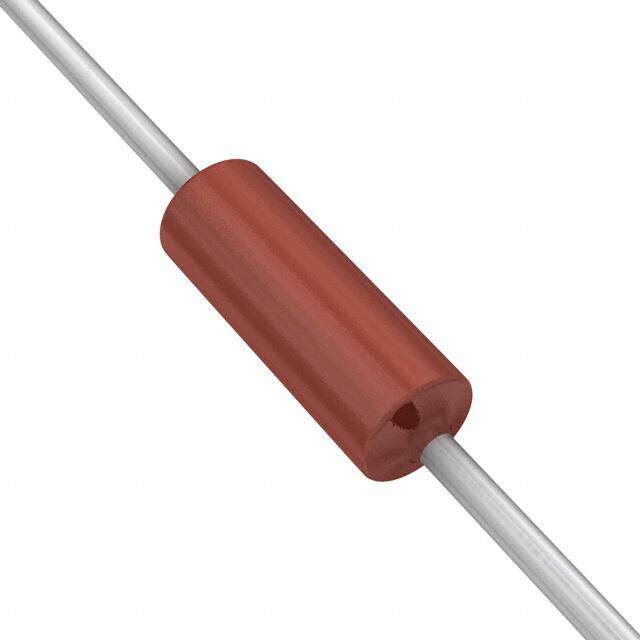
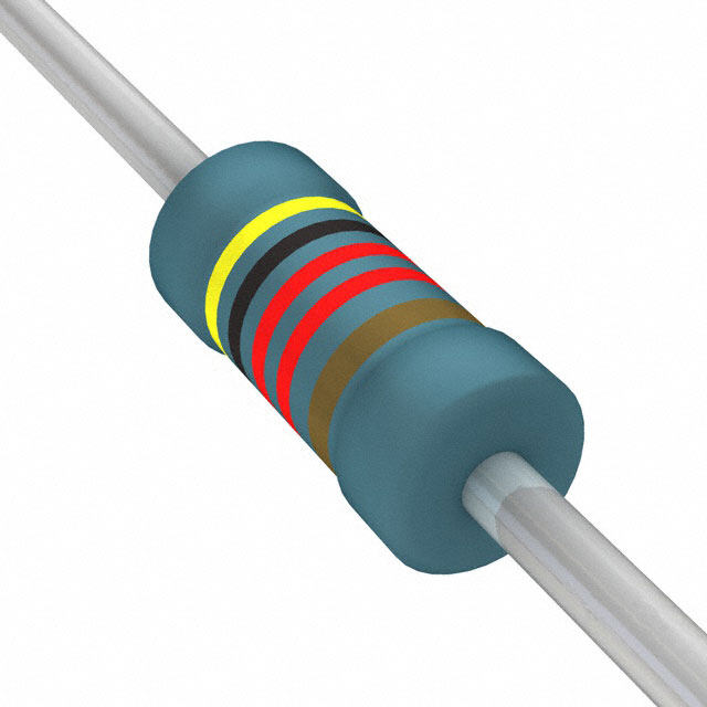
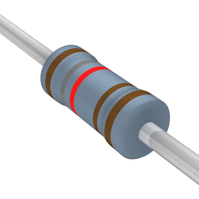
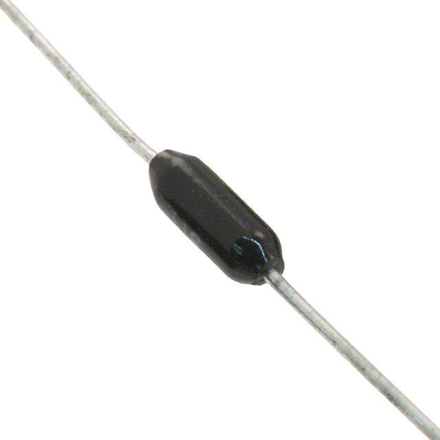
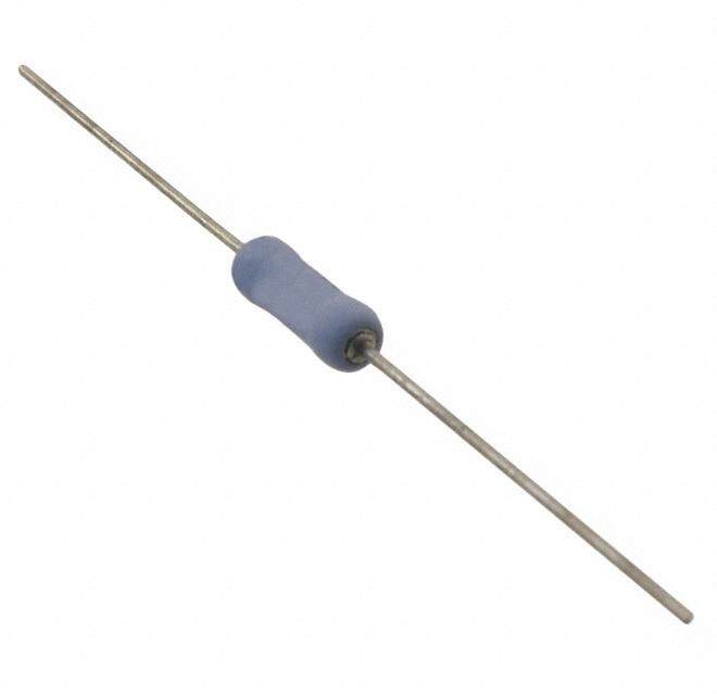
| 产品图片 |
|
| rohs | RoHS 合规性豁免无铅 / 符合限制有害物质指令(RoHS)规范要求 |
| 产品系列 | 线绕电阻器,线绕电阻器 - 透孔,Vishay / Sfernice RWM04104R70JR15E1RWM |
| 数据手册 | |
| 产品型号 | RWM04104R70JR15E1RWM04104R70JR15E1 |
| 产品 | Power Resistors Wirewound Vitreous Enamel |
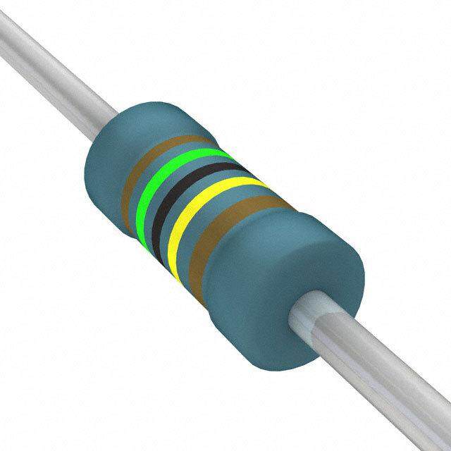
| 产品目录绘图 |
|
| 产品目录页面 | |
| 产品种类 | 线绕电阻器 - 透孔 |
| 供应商器件封装 | 轴向 |
| 其它名称 | RWMA-4.7TR |
| 功率(W) | 3W |
| 功率额定值 | 3 W |
| 包装 | 带卷 (TR) |
| 商标 | Vishay / Sfernice |
| 外壳直径 | 5.5 mm |
| 外壳长度 | 12 mm |
| 大小/尺寸 | 0.217" 直径 x 0.472" 长(5.50mm x 12.00mm) |
| 容差 | ±5%5 % |
| 封装 | Reel |
| 封装/外壳 | 轴向 |
| 工作温度范围 | - 55 C to + 200 C |
| 工厂包装数量 | 1000 |
| 引线直径 | 0.8 mm |
| 成分 | 绕线 |
| 标准包装 | 1,000 |
| 温度系数 | ±75ppm/°C75 PPM / C |
| 特性 | 耐燃 |
| 电压额定值 | 120 V |
| 电阻 | 4.7 Ohms |
| 电阻(Ω) | 4.7 |
| 端子数 | 2 |
| 端接类型 | Axial |
| 类型 | Enamelled Wirewound Power Resistors, Axial Leads |
| 系列 | RWM |
| 高度 | - |





- 商务部:美国ITC正式对集成电路等产品启动337调查
- 曝三星4nm工艺存在良率问题 高通将骁龙8 Gen1或转产台积电
- 太阳诱电将投资9.5亿元在常州建新厂生产MLCC 预计2023年完工
- 英特尔发布欧洲新工厂建设计划 深化IDM 2.0 战略
- 台积电先进制程称霸业界 有大客户加持明年业绩稳了
- 达到5530亿美元!SIA预计今年全球半导体销售额将创下新高
- 英特尔拟将自动驾驶子公司Mobileye上市 估值或超500亿美元
- 三星加码芯片和SET,合并消费电子和移动部门,撤换高东真等 CEO
- 三星电子宣布重大人事变动 还合并消费电子和移动部门
- 海关总署:前11个月进口集成电路产品价值2.52万亿元 增长14.8%


PDF Datasheet 数据手册内容提取
RWM www.vishay.com Vishay Sfernice Enamelled Wirewound Power Resistors Axial Leads FEATURES • High dissipation up to 30 W (25 °C) • Fire proof • Excellent endurance typical drift ± 1.5 % afte r 1000 h • Conformal vitreous enamel • All welded construction • Low ohmic values 0.33 Ω available • Termination: Sn/Ag/Cu As a result of more than 50 years of experience an d • Material categorization: for definitions of complianc e continuous improvements the RWM series of resistor s please see www.vishay.com/doc?99912 features proven reliability in AC or DC applications. The performance of this series of professional resistors fully The high quality of the RWM resides mainly in the use of a meets the requirements of the following specifications: proprietary Vishay Sfernice enamel fired at high temperature - NF C 83-210-001 and free from any compound liable to corrode the resistive - CECC 40201-001 wire. - BS - CECC 40201-002 DIMENSIONS in millimeters 25 min. A 25 min. Ø B Ø 0.8 ± 0.1 RWM RWM RWM RWM RWM RWM 6 x 34 8 x 34 8 x 45 10 x 45 10 x 64 10 x 65 A 33.7 ± 1 33.7 ± 1 45.8 ± 2 45.8 ± 2 63.8 ± 1 63.8 ± 1 Ø B 7.4 ± 1.5 7.4 ± 1.5 9.4 ± 1.5 9.4 ± 1.5 9.4 ± 1.5 9.4 ± 1.5 Weight in g 4 4 8 8 14 14 STANDARD ELECTRICAL SPECIFICATIONS RESISTANCE RATED POWER LIMITING ELEMENT MODEL SIZE RANGE P VOLTAGE TOLERANCE Ω 2W5 °C V ± % RWM 6 x 34 0634 0.33 to 36K 8 500 1, 2, 5 RWM 8 x 34 0834 0.33 to 36K 11 650 1, 2, 5 RWM 8 x 45 0845 0.47 to 62K 11 650 1, 2, 5 RWM 10 x 45 1045 0.47 to 62K 25 800 1, 2, 5 RWM 10 x 64 1064 0.68 to 100K 25 800 1, 2, 5 RWM 10 x 65 1065 0.68 to 100K 30 800 1, 2, 5 Revison: 08-Jul-2020 1 Document Number: 50008 For technical questions, contact: sferfixedresistors@vishay.com THIS DOCUMENT IS SUBJECT TO CHANGE WITHOUT NOTICE. THE PRODUCTS DESCRIBED HEREIN AND THIS DOCUMENT ARE SUBJECT TO SPECIFIC DISCLAIMERS, SET FORTH AT www.vishay.com/doc?91000
RWM www.vishay.com Vishay Sfernice TECHNICAL SPECIFICATIONS VISHAY SFERNICE SERIES AND RWM RWM RWM RWM RWM RWM STYLE 6 x 34 8 x 34 8 x 45 10 x 45 10 x 64 10 x 65 at +70 °C 7 W 9.5 W 9.5 W 21 W 21 W 25.8 W at +25 °C 8 W 11 W 11 W 25 W 25 W 30 W Power Rating With Surface Temp. ≤ +450 °C 12 W 14 W 20 W 25 W 25 W 30 W Ohmic Range in Relation to Tolerance 0.33 Ω 0.33 Ω 0.47 Ω 0.47 Ω 0.68 Ω 0.68 Ω ± 5 % E24 Series 36 kΩ 36 kΩ 62 kΩ 62 kΩ 100 kΩ 100 kΩ Qualified Ohmic Range 0.33 Ω 0.47 Ω NF C 83-210 15 kΩ - 33 kΩ - - - Limiting Element Voltage 500 V 650 V 650 V 800 V 800 V 800 V Critical Resistance 31 kΩ - 38 kΩ 25.6 kΩ 25.6 kΩ 21.3 kΩ PERFORMANCE CECC 40201 - EN 140-201 TYPICAL DRIFTS TESTS CONDITIONS REQUIREMENTS Short Time Overload 10 Pr during 10 s ± (2 % + 0.1 Ω) ± (0.5 % + 0.05 Ω) 25 °C ambient Temperature Cycling -55 °C +200 °C ± (1 % + 0.05 Ω) ± (0.5 % + 0.05 Ω) (5 cycles) Humidity (Steady State) 56 days ± (5 % + 0.1 Ω) ± (0.5 % + 0.05 Ω) 40 °C ambient - R.H. 95 % Tensile test: 20 N Terminal Strength 2 successive bending ± (1 % + 0.05 Ω) ± (0.1 % + 0.05 Ω) 2 full rotations of 180° 1000 h at P r Load Life 90’/30’ cycle ± (5 % + 0.1 Ω) ± (1.5 % + 0.05 Ω) 25 °C ambient OVERLOAD Group Mounting In a still atmosphere, a distance between axes equal to fiv e Heavy overloads can be endured in the form of short pulse s times the resistor’s diameter is recommended. < 0.1 s. Particular requirements should be submitted to Vishay Sfernice, specifying peak voltage, cycle an d Cabinet Mounting environmental conditions. • Unventilated box: Dissipation should be reduced (see dimensional drawing). RECOMMENDATIONS FOR USE • Forced ventilation: If conditions are appropriate , Since these components are high dissipation powe r dissipation may be doubled or even trebled. resistors, customers are advised to use a high melting poin t • In any case: The surface temperature at the hottest point solder. should not exceed 450 °C. For low ohmic values, the measurement becomes critical These aspects should be considered by the end user. and the connecting wires resistance is to be included. Th e value is measured at 5 mm from the resistor body. ELECTRICAL SPECIFICATIONS Standard ± 5 % (NI ± 10 %) Tolerance On request ± 1 % and ± 2 % (NI ± 5 %) Temperature Coefficient +75 ppm/°C typical Dielectric Withstanding Voltage NF EN140000 500 V - 1 min - 10 mA RMS Inductance Non inductive (Ayrton-Perry) winding available Revison: 08-Jul-2020 2 Document Number: 50008 For technical questions, contact: sferfixedresistors@vishay.com THIS DOCUMENT IS SUBJECT TO CHANGE WITHOUT NOTICE. THE PRODUCTS DESCRIBED HEREIN AND THIS DOCUMENT ARE SUBJECT TO SPECIFIC DISCLAIMERS, SET FORTH AT www.vishay.com/doc?91000
RWM www.vishay.com Vishay Sfernice POWER RATING TYPICAL TEMPERATURE RISE 500 % 110106 E IN °C 400 6 x 348 x 34 8 x 45 10 x 45 10 x 160 4x 65 N UR R I 75 AT E R 300 W E O P P M ATED 50 OT TE 200 R P 25 S T 100 O H 0 0 0 25 100 200 300 350 0 2 4 6 8 10 12 14 16 18 20 22 24 26 28 30 AMBIENT TEMPERATURE IN °C RATED POWER IN W MARKING Vishay Sfernice trademark, model and style if applicable, ohmic value, resistance tolerance, manufacturing date (year - month). ORDERING INFORMATION RWM 6 x 34 XXX 1U2 ± 5 % BO50 e1 MODEL STYLE NI OPTIONAL SPECIAL OHMIC VALUE TOLERANCE PACKAGING LEAD DESIGN (Pb)-FREE Non inductive Method N° Custom items winding optional are subject to extra charge and minimum order. Please see price list. GLOBAL PART NUMBER INFORMATION R W M 0 6 3 4 1 R 2 0 J S 0 9 E 1 GLOBAL LEAD SIZE OPTION OHMIC VALUE TOLERANCE PACKAGING SPECIAL MODEL (Pb)-FREE RWM d x L: Blank The first three digits are F = 1 % Size 0845, As Sn(99), 0634 significant figures and the G = 2 % 1045, 1064, applicable. Ag(0.3), 0834 or last digit specifies the J = 5 % 1065: Ex: AD5 Cu(0.7): 0845 number of zeros to follow. K = 10 % B25 = box E1 1045 N R designates decimal point. (50 pieces) 1064 48R7 = 48.7 Ω 1065 (non inductive 1R20 = 1.2 Ω Size 0634: winding) 1002 = 10 000 Ω S09 = bag R330 = 0.33 Ω (50 pieces) ... Revison: 08-Jul-2020 3 Document Number: 50008 For technical questions, contact: sferfixedresistors@vishay.com THIS DOCUMENT IS SUBJECT TO CHANGE WITHOUT NOTICE. THE PRODUCTS DESCRIBED HEREIN AND THIS DOCUMENT ARE SUBJECT TO SPECIFIC DISCLAIMERS, SET FORTH AT www.vishay.com/doc?91000
Legal Disclaimer Notice www.vishay.com Vishay Disclaimer ALL PRODUCT, PRODUCT SPECIFICATIONS AND DATA ARE SUBJECT TO CHANGE WITHOUT NOTICE TO IMPROV E RELIABILITY, FUNCTION OR DESIGN OR OTHERWISE. Vishay Intertechnology, Inc., its affiliates, agents, and employees, and all persons acting on its or their behalf (collectively, “Vishay”), disclaim any and all liability for any errors, inaccuracies or incompleteness contained in any datasheet or in any other disclosure relating to any product. Vishay makes no warranty, representation or guarantee regarding the suitability of the products for any particular purpose o r the continuing production of any product. To the maximum extent permitted by applicable law, Vishay disclaims (i) any and all liability arising out of the application or use of any product, (ii) any and all liability, including without limitation special, consequential or incidental damages, and (iii) any and all implied warranties, including warranties of fitness for particular purpose, non-infringement and merchantability. Statements regarding the suitability of products for certain types of applications are based on Vishay’s knowledge of typical requirements that are often placed on Vishay products in generic applications. Such statements are not binding statements about the suitability of products for a particular application. It is the customer’s responsibility to validate that a particular product with the properties described in the product specification is suitable for use in a particular application. Parameters provided in datasheets and / or specifications may vary in different applications and performance may vary over time. All operating parameters, including typical parameters, must be validated for each customer application by the customer’s technical experts. Product specifications do not expand or otherwise modify Vishay’s terms and conditions of purchase, including but not limited to the warranty expressed therein. Except as expressly indicated in writing, Vishay products are not designed for use in medical, life-saving, or life-sustainin g applications or for any other application in which the failure of the Vishay product could result in personal injury or death. Customers using or selling Vishay products not expressly indicated for use in such applications do so at their own risk . Please contact authorized Vishay personnel to obtain written terms and conditions regarding products designed for such applications. No license, express or implied, by estoppel or otherwise, to any intellectual property rights is granted by this documen t or by any conduct of Vishay. Product names and markings noted herein may be trademarks of their respective owners. © 2019 VISHAY INTERTECHNOLOGY, INC. ALL RIGHTS RESERVED Revision: 01-Jan-2019 1 Document Number: 91000