ICGOO在线商城 > 电阻器 > 芯片电阻 - 表面安装 > RC0402JR-0775RL
 Datasheet下载
- 型号: RC0402JR-0775RL
- 制造商: YAGEO AMERICA CORPORATION
- 库位|库存: xxxx|xxxx
- 要求:
| 数量阶梯 | 香港交货 | 国内含税 |
| +xxxx | $xxxx | ¥xxxx |
查看当月历史价格
查看今年历史价格
RC0402JR-0775RL产品简介:
ICGOO电子元器件商城为您提供RC0402JR-0775RL由YAGEO AMERICA CORPORATION设计生产,在icgoo商城现货销售,并且可以通过原厂、代理商等渠道进行代购。 RC0402JR-0775RL价格参考¥0.00-¥0.00。YAGEO AMERICA CORPORATIONRC0402JR-0775RL封装/规格:芯片电阻 - 表面安装, 75 Ohms ±5% 0.063W,1/16W 厚膜 芯片电阻 0402(1005 公制) 防潮 厚膜。您可以下载RC0402JR-0775RL参考资料、Datasheet数据手册功能说明书,资料中有RC0402JR-0775RL 详细功能的应用电路图电压和使用方法及教程。
Yageo(国巨)的RC0402JR-0775RL是一款芯片电阻,属于表面安装器件(SMD),其主要应用场景如下:

 1. 电源管理电路
   - 该型号电阻常用于电源管理模块中,例如稳压器、DC-DC转换器和LDO(低压差线性稳压器)。它能够精确控制电流,确保电路稳定运行。
   - 其阻值为75Ω,适合用作分流电阻或反馈网络中的元件。

 2. 信号调理电路
   - 在信号处理电路中,如放大器、滤波器或传感器接口,RC0402JR-0775RL可用于调节增益、匹配阻抗或衰减信号。
   - 小尺寸(0402英制)使其非常适合高密度设计,适用于手持设备或便携式电子产品。

 3. 通信设备
   - 在无线通信模块中,如Wi-Fi、蓝牙或射频前端,该电阻可作为匹配网络的一部分,优化信号传输性能。
   - 它还能用于偏置电路,为晶体管或其他有源器件提供稳定的直流工作点。

 4. 消费电子
   - 广泛应用于智能手机、平板电脑、智能手表等消费类电子产品中。由于其小尺寸和高可靠性,特别适合需要紧凑设计的场景。
   - 可用于LED驱动电路中的限流功能,保护LED免受过流损坏。

 5. 工业控制
   - 在工业自动化设备中,如PLC(可编程逻辑控制器)或数据采集系统,该电阻可用于输入/输出接口的保护和信号调理。
   - 其耐高温特性和稳定性使其能够在恶劣环境下长期可靠工作。

 6. 汽车电子
   - 适用于车载信息娱乐系统、导航设备或传感器接口。尽管不是车规级产品,但在非关键部位仍可发挥作用。
   - 用于电流检测或温度补偿电路,确保系统运行在安全范围内。

 总结
Yageo RC0402JR-0775RL凭借其小巧的尺寸、高精度和良好的稳定性,广泛应用于各类电子设备中。无论是消费级产品还是工业级应用,这款电阻都能满足对空间和性能有严格要求的设计需求。
| 参数 | 数值 |
| 产品目录 | |
| 描述 | RES 75 OHM 1/16W 5% 0402 SMD |
| 产品分类 | |
| 品牌 | Yageo |
| 数据手册 | |
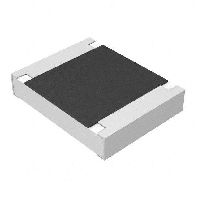
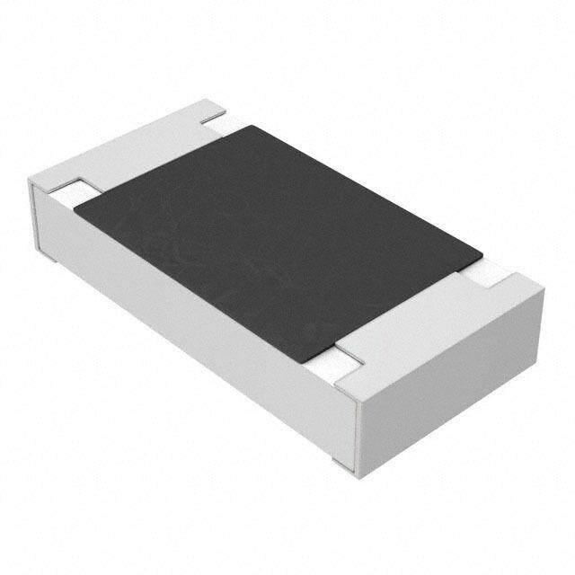
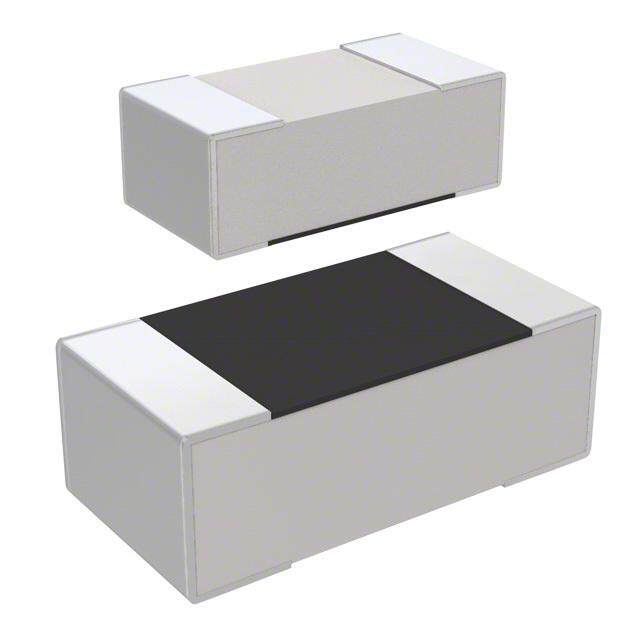
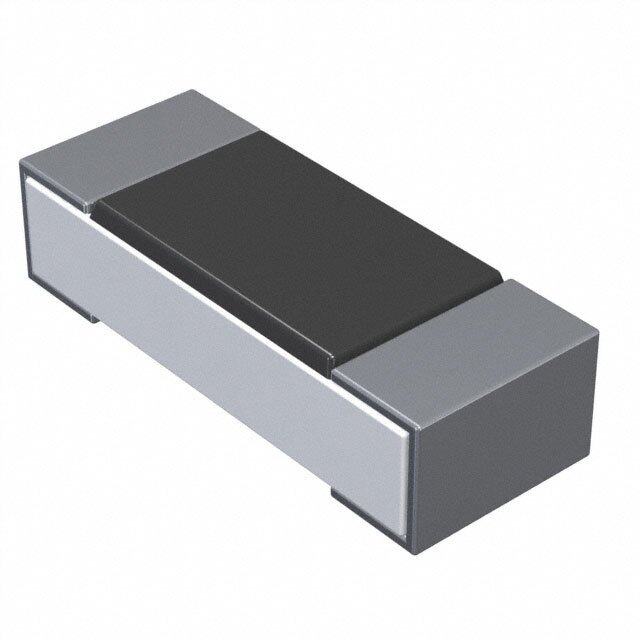
| 产品图片 |
|
| 产品型号 | RC0402JR-0775RL |
| rohs | 无铅 / 符合限制有害物质指令(RoHS)规范要求 |
| 产品系列 | RC0402 |
| 产品目录绘图 |
|
| 产品目录页面 | |
| 供应商器件封装 | 0402 |
| 其它名称 | 311-75JRCT |
| 功率(W) | 0.063W,1/16W |
| 包装 | 剪切带 (CT) |
| 大小/尺寸 | 0.039" 长 x 0.020" 宽(1.00mm x 0.50mm) |
| 容差 | ±5% |
| 封装/外壳 | 0402(1005 公制) |
| 工作温度 | -55°C ~ 155°C |
| 工具箱 | /product-detail/zh/PHJ1A-KIT/PHJ1A-KIT-ND/383648/product-detail/zh/PHJ1-KIT/PHJ1-KIT-ND/383649 |
| 成分 | 厚膜 |
| 标准包装 | 1 |
| 温度系数 | ±100ppm/°C |
| 特性 | 防潮 |
| 电阻(Ω) | 75 |
| 端子数 | 2 |
| 高度 | 0.016"(0.40mm) |


- 商务部:美国ITC正式对集成电路等产品启动337调查
- 曝三星4nm工艺存在良率问题 高通将骁龙8 Gen1或转产台积电
- 太阳诱电将投资9.5亿元在常州建新厂生产MLCC 预计2023年完工
- 英特尔发布欧洲新工厂建设计划 深化IDM 2.0 战略
- 台积电先进制程称霸业界 有大客户加持明年业绩稳了
- 达到5530亿美元!SIA预计今年全球半导体销售额将创下新高
- 英特尔拟将自动驾驶子公司Mobileye上市 估值或超500亿美元
- 三星加码芯片和SET,合并消费电子和移动部门,撤换高东真等 CEO
- 三星电子宣布重大人事变动 还合并消费电子和移动部门
- 海关总署:前11个月进口集成电路产品价值2.52万亿元 增长14.8%


PDF Datasheet 数据手册内容提取
DATA SHEET GENERAL PURPOSE CHIP RESISTORS RC_L series ±0.1%, ±0.5%, ±1%, ±5% Sizes 0075/0100/0201/0402/0603/0805/ 1206/1210/1218/2010/2512 RoHS compliant & Halogen free 0 1 V. 8 1 0 2 2, 1 r e b m e c De – n o ti a c cifi e p s t c u d o r P
Product specification 2 Chip Resistor Surface Mount RC_L SERIES 0075 to 2512 11 SCOPE ORDERING INFORMATION - GLOBAL PART NUMBER This specifica tion describes RC series chip resistors with lead Global part numbers are identified by the series, size, tolerance, packing free terminations made by thick type, temperature coefficient, taping reel and resistance value. film process. G LOBAL PART NUMBER RC XXXX X X X XX XXXX L APPLICATIONS (1) (2) (3) (4) (5) (6) (7) All general purpose application (1) SIZE 0075/0100/0201/0402/0603/0805/1206/1210/1218/2010/2512 (2) TOLERANCE FEATURES Halogen Free Epoxy B = ±0.1% RoHS compliant D = ±0.5% F = ±1.0% Products with lead free J = ±5.0% (for jumper ordering, use code of J) terminations meet RoHS requirements (3) TAPING REEL & POWER Pb-glass contained in R = Paper taping reel electrodes, resistors element K = Embossed taping reel and glass are exempted by S = ESD safe reel (0075/0100 only) RoHS Reducing environmentally (4) TEMPERATURE COEFFICIENT OF RESISTANCE hazardous wastes - = Based on spec. High component and equipment (5) TAPING REEL reliability Saving of PCB space 07 = 7 inch dia. Reel None forbidden-materials used in 10=10 inch dia. Reel products/production 13 =13 inch dia. Reel 7W = 7 inch dia. Reel & 2 x standard power 7N = 7 inch dia. Reel, ESD safe reel (0075/0100 only) 3W = 13 inch dia. Reel & 2 x standard power (6) RESISTANCE VALUE There are 2~4 digits indicated the resistance value. Letter R/K/M is decimal point Example: 97R6 = 97.6Ω 9K76 = 9760Ω 1M = 1,000,000Ω (7) DEFAULT CODE Letter L is the system default code for ordering only.(Note) ORDERING EXAMPLE The ordering code for a RC0402 0.0625W chip resistor value 100KΩwith ±5% tolerance, supplied in 7-inch tape reel of 10,000 units per reel is: RC0402JR-07100KL. NOTE 1. All our RSMD products meet RoHS compliant and Halogen Free. "LFP" of the internal 2D reel label mentions "Lead Free Process". 2. On customized label, "LFP" or specific symbol can be printed. www.yageo.com Dec. 12, 2018 V.10
Product specification 3 Chip Resistor Surface Mount RC_L SERIES 0075 to 2512 11 M ARKING RC0075 / RC01 00 / RC0201 / RC0402 No Marking Fig. 1 R C 0603 0 1%, 0.5%,E24 exception values 10/11/13/15/20/75 of E24 series Fig. 2 240 = 24 × 100 = 24 88 1%, 0.5%, E96 refer to EIA-96 marking method, including values 10/11/13/15/20/75 of E24 series Fig. 3 88A = 806 × 100 = 806 Ω 03 5%, E24 series : 3 digits First two digits for significant figure and 3rd digit for number of zeros F ig. 4 Value = 10 KΩ RC0805 / RC1206 / RC1210 / RC2010 / RC2512 00 1%, 0.5%, E24/E96 series : 4 digits First three digits for significant figure and 4th digit for number of zeros Fig. 5 Value = 10 KΩ PF series Note: construction will be adjusted to resistance value 03 5%, E24 series : 3 digits (only for PF series). First two digits for significant figure and 3rd digit for number of zeros Fig. 6 Value = 10 KΩ RC 1218 E-24 series: 3 digits, ±5% First two digits for significant figure and 3rd digit for number of zeros Fig. 7 Value = 10 KΩ 00 Both E-24 and E-96 series: 4 digits, ±1% & ±0.5% First three digits for significant figure and 4th digit for number of zeros Fig. 8 Value = 10 KΩ F or further marking information, please see special data sheet "Chip resistors marking". www.yageo.com Dec. 12, 2018 V.10
Product specification 4 Chip Resistor Surface Mount RC_L SERIES 0075 to 2512 11 TAPING CO DE & POWER Power, W (P70) Power, W (P70) Coding Coding Type 07 7W Type 07 7W 0075 1/50 1206 1/4 1/2 0100 1/32 1210 1/2 0201 1/20 1218 1 0402 1/16 1/8 2010 3/4 0603 1/10 1/5 2512 1 2 0805 1/8 1/4 CONSTRUCTION OOuuttlliinneess The resistor is constructed on top of a high-grade ceramic body. Internal metal electrodes are added For dimensions, please refer to Table 1 on each end to make the contacts to the thick film resistive element. The composition of the resistive element is a noble metal imbedded into a glass and covered by a second glass to prevent environmental influences. The resistor is laser trimmed to the rated resistance value. The resistor is covered with a protective epoxy coat, finally the two external terminations (matte tin on Ni-barrier) are added, as shown in Fig.9. 9 Fig. 9 Chip resistor outlines DIMENSION Table 1 T YPE L (mm) W (mm) H (mm) I1 (mm) I2 (mm) RC0075 0.30±0.01 0.15±0.01 0.13±0.01 0.08±0.03 0.08±0.03 R C0100 0.40±0.02 0.20±0.02 0.13±0.02 0.10±0.03 0.10±0.03 RC0201 0.60±0.03 0.30±0.03 0.23±0.03 0.10±0.05 0.15±0.05 R C0402 1.00±0.05 0.50±0.05 0.35±0.05 0.20±0.10 0.25±0.10 R C0603 1.60±0.10 0.80±0.10 0.45±0.10 0.25±0.15 0.25±0.15 RC0805 2.00±0.10 1.25±0.10 0.50±0.10 0.35±0.20 0.35±0.20 R C1206 3.10±0.10 1.60±0.10 0.55±0.10 0.45±0.20 0.40±0.20 R C1210 3.10±0.10 2.60±0.15 0.55±0.10 0.45±0.15 0.50±0.20 RC1218 3.10±0.10 4.60±0.10 0.55±0.10 0.45±0.20 0.40±0.20 R C2010 5.00±0.10 2.50±0.15 0.55±0.10 0.45±0.15 0.50±0.20 RC2512 6.35±0.10 3.10±0.15 0.55±0.10 0.60±0.20 0.50±0.20 www.yageo.com Dec. 12, 2018 V.10
Product specification 5 Chip Resistor Surface Mount RC_L SERIES 0075 to 2512 11 E LECTRICAL CHARACTERISTIC S Table 2 C HARAC- POWER OPERATING MAXIMUM MAXIMUM DIELECTRIC RESISTANCE TEMPERATURE JUMPER T ERISTICS TEMPERATURER WORKING OVERLOAD WITHSTANDING RANGE COEFFICIENT CRITERIA ANGE VOLTAGE VOLTAGE VOLTAGE 5% (E24) 10Ω≦R<100Ω Rated Current 10Ω≦R≦1MΩ -200~+600ppm℃ 0.5A RFCig.0 40 75C hip resis1 t/o50r Wou tline-s5 5℃ to 125℃ 10V 25V 25V 1% (E24/E96) 100Ω≦R≦1MΩ Maximum 10Ω≦R≦1MΩ ±200ppm℃ Current Jumper<50mΩ 1.0A 5% (E24) 1Ω≦R<10Ω Rated Current 1Ω≦R≦22MΩ -200~+600ppm℃ 0.5A 1% (E24/E96) 10Ω≤ R < 100Ω: Maximum 1Ω≦R≦10MΩ ±300ppm/°C Current R C0100 1/32 W -55℃ to 125℃ 15V 30V 30V 0.5% (E24/E96) 100Ω≤ R ≤ 10MΩ: 1.0A 33Ω≦R≦470KΩ ±200ppm/°C Jumper<50mΩ 10MΩ< R ≤ 22MΩ: ±250ppm/°C 5% (E24) 1Ω≦R≦10Ω Rated Current 1Ω≦R≦10MΩ -100~+350ppm℃ 0.5A 1% (E24/E96) 10Ω<R≦10MΩ Maximum R C0201 1/20 W -55℃ to 125℃ 25V 50V 50V 1Ω≦R≦10MΩ ±200ppm℃ Current 0.1%, 0.5% (E24/E96) 1.0A 10Ω≦R≦1MΩ Jumper<50mΩ 5% (E24) 1Ω≦R≦10Ω R a t ed Current 1Ω≦R≦22MΩ ±200ppm℃ 1.0A 1% (E24/E96) 10Ω<R≦10MΩ Maximum 1/16 W -55℃ to 155℃ 50V 100V 100V 1Ω≦R≦10MΩ ±100ppm℃ Current 0.1%, 0.5% (E24/E96) 10MΩ<R≦22MΩ 2.0A 10Ω≦R≦1MΩ ±200ppm℃ RC0402 Jumper<50mΩ 5% (E24) 1Ω≦R≦1MΩ 1Ω≦R≦1MΩ 1/8W -55℃ to 155℃ 50V 100V 100V 1% (E24/E96) ±200ppm℃ 1Ω≦R≦1MΩ 5% (E24) 1Ω≦R≦10Ω R a t ed Current 1Ω≦R≦22MΩ ±200ppm℃ 1.0A 1% (E24/E96) 10Ω<R≦10MΩ Maximum 1/10 W -55℃ to 155℃ 75V 150V 150V 1Ω≦R≦10MΩ ±100ppm℃ Current 0.1%, 0.5% (E24/E96) 10MΩ<R≦22MΩ 2.0A 10Ω≦R≦1MΩ ±200ppm℃ RC0603 Jumper<50mΩ 5% (E24) 1Ω≦R≦1MΩ 1Ω≦R≦1MΩ ±200ppm℃ 1/5 W -55℃ to 155℃ 75V 150V 150V 1% (E24/E96) 1Ω≦R≦1MΩ www.yageo.com Dec. 12, 2018 V.10
Product specification 6 Chip Resistor Surface Mount RC_L SERIES 0075 to 2512 11 Table 2 CHARAC- POWER OPERATING MAXIMUM MAXIMUM DIELECTRIC RESISTANCE TEMPERATURE JUMPER TERISTICS TEMPERATURER WORKING OVERLOAD WITHSTANDING RANGE COEFFICIENT CRITERIA ANGE VOLTAGE VOLTAGE VOLTAGE 5% (E24) 1Ω≦R≦10Ω R a t e d Current 1Ω≦R≦100MΩ ±200ppm℃ 2.0A 1% (E24/E96) 10Ω<R≦10MΩ Maximum 1Ω≦R≦10MΩ ±100ppm℃ Current 1/8 W -55℃ to 155℃ 150V 300V 300V 0.1%, 0.5% (E24/E96) 10MΩ<R≦22MΩ 5.0A 10Ω≦R≦1MΩ ±200ppm℃ 10%, 20% (E24) 24MΩ<R≦100MΩ RC0805 24MΩ≦R≦100MΩ ±300ppm℃ Jumper<50mΩ 5% (E24) 1Ω≦R≦1MΩ 1Ω≦R≦1MΩ ±200ppm℃ 1/4 W -55℃ to 155℃ 150V 300V 300V 1% (E24/E96) 1Ω≦R≦1MΩ 5% (E24) 1Ω≦R≦10Ω R a t e d Current 1Ω≦R≦100MΩ ±200ppm℃ 2.0A 1% (E24/E96) 10Ω<R≦10MΩ Maximum 1Ω≦R≦10MΩ ±100ppm℃ Current 1/4 W -55℃ to 155℃ 200V 400V 500V 0.1%, 0.5% (E24/E96) 10MΩ<R≦22MΩ 10.0A 10Ω≦R≦1MΩ ±200ppm℃ 10%, 20% (E24) 24MΩ≦R≦100MΩ RC1206 24MΩ≦R≦100MΩ ±300ppm℃ Jumper<50mΩ 5% (E24) 1Ω≦R≦1MΩ 1Ω≦R≦1MΩ ±200ppm℃ 1/2 W -55℃ to 155℃ 200V 400V 500V 1% (E24/E96) 1Ω≦R≦1MΩ 5% (E24) 1Ω≦R≦10Ω R a t ed Current 1Ω≦R≦22MΩ ±200ppm℃ 2.0A 1% (E24/E96) 10Ω<R≦10MΩ Maximum 1Ω≦R≦10MΩ ±100ppm℃ Current RC1210 1/2 W -55℃ to 155℃ 200V 500V 500V 0.1%, 0.5% (E24/E96) 10MΩ<R≦22MΩ 10.0A 10Ω≦R≦1MΩ ±200ppm℃ Jumper<50mΩ 5% (E24) 1Ω≦R≦10Ω R a t ed Current 1Ω≦R≦1MΩ ±200ppm℃ 6.0A 1% (E24/E96) 10Ω<R≦1MΩ Maximum 1Ω≦R≦1MΩ ±100ppm℃ Current RC1218 1 W -55℃ to 155℃ 200V 500V 500V 0.1%, 0.5% (E24/E96) 10.0A 10Ω≦R≦1MΩ Jumper<50mΩ www.yageo.com Dec. 12, 2018 V.10
Product specification 7 Chip Resistor Surface Mount RC_L SERIES 0075 to 2512 11 Table 2 CHARAC- PO WER OPERATING MAXIMUM MAXIMUM DIELECTRIC RESISTANCE TEMPERATURE JUMPER TERISTICS TEMPERATURER WORKING OVERLOAD WITHSTANDING RANGE COEFFICIENT CRITERIA ANGE VOLTAGE VOLTAGE VOLTAGE 5% (E24) 1Ω≦R≦10Ω R a t ed Current 1Ω≦R≦22MΩ ±200ppm℃ 2.0A 1% (E24/E96) 10Ω<R≦10MΩ Maximum 1Ω≦R≦10MΩ ±100ppm℃ Current RC2010 3/4 W -55℃ to 155℃ 200V 500V 500V 0.1%, 0.5% (E24/E96) 10MΩ<R≦22MΩ 10.0A 10Ω≦R≦1MΩ ±200ppm℃ Jumper<50mΩ 5% (E24) 1Ω≦R≦10Ω R a t ed Current 1Ω≦R≦22MΩ ±200ppm℃ 2.0A 1% (E24/E96) 10Ω<R≦10MΩ Maximum 1Ω≦R≦10MΩ ±100ppm℃ Current 1 W -55℃ to 155℃ 200V 500V 500V 0.1%, 0.5% (E24/E96) 10MΩ<R≦22MΩ 10.0A 10Ω≦R≦1MΩ ±200ppm℃ RC2512 Jumper<50mΩ 5% (E24) 1Ω≦R≦1MΩ 1Ω≦R≦1MΩ ±200ppm℃ 2 W -55℃ to 155℃ 200V 400V 500V 1% (E24/E96) 1Ω≦R≦1MΩ FOOTPRINT AND SOLDERING PROFILES For recommended footprint and soldering profiles, please refer to data sheet “Chip resistors mounting” www.yageo.com Dec. 12, 2018 V.10
Product specification 8 Chip Resistor Surface Mount RC_L SERIES 0075 to 2512 11 PACKING ST YLE AND PACKAGING QUANTITY Table 3 Packing style and packaging quantity PACKING STYLE PAPER TAPING REEL (R) ESD SAFE REEL (S) EMBOSSED (4MM WIDTH, 1MM TAPING REEL PITCH PLASTIC EMBOSSED) REEL DIMENSI ON 7" (178 mm) 10" (254mm) 13" (330 mm) 7" (178 mm) 7" (178 mm) RC0075 --- --- --- 20000 --- RC0100 20000 --- 80000 40000 --- RC0201 10000 20000 50000 --- --- RC0402 10000 20000 50000 --- --- RC0603 5000 10000 20000 --- --- RC0805 5000 10000 20000 --- --- RC1206 5000 10000 20000 --- --- RC1210 5000 10000 20000 --- --- RC1218 --- --- --- --- 4000 RC2010 --- --- --- --- 4000 RC2512 --- --- --- --- 4000 NOTE For tape and reel specification/dimensions, please refer to data sheet “Chip resistors packing”. FUNCTIONAL DESCRIPTION OOPPEERRAATTIINNGG TTEEMMPPEERRAATTUURREE RRAANNGGEE RC0402 to RC2512 Range: -55℃ to +155℃ (Fig. 10-1) RC0075 to RC0201 Range: -55℃ to +125℃ (Fig. 10-2) PPOOWWEERR RRAATTIINNGG Each type rated power at 70 °C: RC0075=1/50W RC0100=1/32W RC0201=1/20W RC0402=1/16W, 1/8W RC0603=1/10W, 1/5W RC0805=1/8W, 1/4W Fig. 10-1 Maximum dissipation (P) in percentage of rated poweras a function of the operating ambient RC1206=1/4W, 1/2W temperature (Tamb) RC1210=1/2W RC1218=1W RC2010=3/4W RC2512=1W, 2W RATED VOLTAGE The DC or AC (rms) continuous working voltage corresponding to the rated power is determined by the following formula: V = (PxR) or max. working voltage whichever is less Where V = Continuous rated DC or AC (rms) working voltage (V) Fig. 10-2 Maximum dissipation (P) in percentage of rated P = Rated power (W) poweras a function of the operating ambient temperature (Tamb) R = Resistance value (Ω) www.yageo.com Dec. 12, 2018 V.10
Product specification 9 Chip Resistor Surface Mount RC_L SERIES 0075 to 2512 11 T ESTS AND R EQUIREMENTS Table 4 Test condition, procedure and requirements TEST TEST METHOD PROCEDURE REQUIREMENTS Temperature MIL-STD-202 Method 304 At +25/–55°C and +25/+125°C Refer to table 2 Coefficient of Resistance Formula: (T.C.R.) R2R1 T.C.R= ×106 (ppm/°C) R1(t2t1) Where t =+25 °C or specified room temperature 1 t =–55 °C or +125 °C test temperature 2 R =resistance at reference temperature in ohms 1 R =resistance at test temperature in ohms 2 Life/ Endurance MIL-STD-202 Method 108A At 70±2°C for 1,000 hours; RCWV applied for 0075: ± (5%+100mΩ) IEC 60115-1 4.25.1 1.5 hours on and 0.5 hour off, still air required <100mΩ for jumper 01005: ±(3% +50mΩ) <100mΩf or jumper Others: ±(1%+50mΩ) for B/D/F tol ±(3%+50mΩ) for J tol <100mR for jumper High MIL-STD-202 Method 108A 1,000 hours at maximum operating temperature 0075: ± (5%+100mΩ) Temperature IEC 60068-2-2 depending on specification, unpowered. <100mΩ for jumper Exposure 01005: ±(1% +50mΩ) < 50mΩf or jumper Others: ±(1%+50mΩ) for B/D/F tol ±(2%+50mΩ) for J tol <50mR for jumper Moisture MIL-STD-202 Method 106G Each temperature / humidity cycle is defined at 0075: ± (2%+100mΩ) Resistance 8 hours (method 106F), 3 cycles / 24 hours for <100mΩ for jumper 01005: ±(2% +50mΩ) 10d with 25°C / 65°C 95% R.H, without steps < 100mΩf or jumper 7a & 7b, unpowered Others: Parts mounted on test-boards, without ±(0.5%+50mΩ) for B/ D/F tol condensation on parts ±(2%+50mΩ) for J tol <100mR for jumper Humidity IEC 60115-1 4.24.2 Steady state for 1000 hours at 40°C / 95% R.H. 0075: ± (5%+100mΩ) no visible damage RCWV applied for 1.5 hours on and 01005: ±(3% +50mΩ) 0.5 hour off < 100mΩf or jumper Others: ±(1%+50mΩ) for B/D/F tol ±(2%+50mΩ) for J tol <100mR for jumper www.yageo.com Dec. 12, 2018 V.10
Product specification 10 Chip Resistor Surface Mount RC_L SERIES 0075 to 2512 11 Thermal MIL-STD-202 Method 107G -55/+125°C 0075/01005: ±(1% +50mΩ) Shock < 50mΩf or jumper Note Number of cycles required is 300. Others: Devices mounted Maximum transfer time is 20 seconds. ±(0.5%+50mΩ) for B/D/F tol Dwell time is 15 minutes. Air - Air ±(1%+50mΩ) for J tol < 50mR for jumper Short Time IEC 60115-1 4.13 2.5 times RCWV or maximum overload voltage 0075/01005: ±(2% +50mΩ) Overload which is less for 5 seconds at room temperature < 50mΩf or jumper Others: ±(1%+50mΩ) for B/D/F tol ±(2%+50mΩ) for J tol <50mR for jumper No visible damage Board Flex/ IEC 60115-1 4.33 Device mounted or as described only 1 board 0075/01005: ±(1% +50mΩ) Bending bending required < 50mΩf or jumper Others: bending time: 60±5 seconds ±(1%+50mΩ) for B/D/F/J tol 0075/0100/0201/0402:5mm; 0603/0805:3mm; <50mR for jumper 1206 and above:2mm No visible damage Solderability J-STD-002 test B Electrical Test not required Magnification 50X W ell tinned - Wetting SMD conditions: (>95% covered) 1st step: method B, aging 4 hours at 155°C No visible damage dry heat 2nd step: leadfree solder bath at 245±3°C Dipping time: 3±0.5 seconds -Leaching J-STD-002 test D Leadfree solder ,260°C, 30 seconds immersion No visible damage time -Resistance to MIL-STD-202 Method 210F Condition B, no pre-heat of samples 0075: ± (3%+50mΩ) Soldering Heat IEC 60115-1 4.18 Leadfree solder, 260°C ±5°C, 10 ±1 seconds <50mΩ for jumper 01005: ±(1% +50mΩ) immersion time < 50mΩf or jumper Procedure 2 for SMD: devices fluxed and Others: cleaned with isopropanol ±(0.5% +50mΩ) for B/D/F tol. ±(1% +50mΩ) for J tol. <50mR for jumper No visible damage www.yageo.com Dec. 12, 2018 V.10
Product specification 11 Chip Resistor Surface Mount RC_L SERIES 0075 to 2512 11 R EVISION HI STORY REVISION DATE CHANGE NOTIFICATION DESCRIPTION TEMPERATURE COEFFICIENT Version 1T0 YPE Dec. 12, 2018 - POWER TOL-E URpAdNatCedE 0075R dEiSmISeTnAsioNnCs E RANGE OF RESISTANCE Version 90 60M 3ar. 016/, 1200W18, 1/5- W, 3/10W, 2/5W, 1/2W - Add 0.5%/1% mark5i nmg Ωru≦le R f o<r 1R0C0 0m6Ω03 ~ RC2512 based on marking 080 5 1/8W, 1/4W, 1/3W, 1/2W datasheet 4 mΩ ≦ R < 100 mΩ Version 8 Ju ly 10, 2017 - - Add "3W" part number coding for 13" Reel & double power 1206 1/4W, 1/2W 3 mΩ ≦ R < 100 mΩ Version 7 Mar.1 7/2, W20,1 17W - - Add 10" packing The resistors are constructed using outstanding TCR level Version 6 Feb.1m5a, t2e0r1ia7l , wh- ich makes Yageo PF - Extend RC0805 and RC1206 resistance range to 100Mohm resistors excellent for current Version 5 Oct.s 0e6n,s 2in0g1 6a pp-li cation in battery - Description: Update Dimension of I2 of RC2512 (2W) charger circuit & DC-DC converter. Version 4 Jan. 22, 2016 - - Update resistance range The composition of the resistive ±1% PF 2010 material is adjusted to give the ±2% 5 mΩ ≦ R < 100 mΩ ±75 ppm/°C Version 3 Deca. 2p4p,r 2o0x1i5m at-e required resistance - Updated test and requirements ±5% and is covered with a protective coating, which printed with the Version 2 Jul. 23, 2015 - - Updated test and requirements resistance value. Finally, the three external Version 1 Jan. 2te1r, m20i1n5a tion-s (Ni / matte Tin) are - ESD Safe Reel update added, as shown in Fig. 4. Version 0 Dec. 15, 2014 - - First issue of this specification 1W, 2W 1 mΩ ≦ R < 100 mΩ 2512 3W 1 mΩ ≦ R ≦ 50 mΩ 4527 2W, 3W, 5W 6 mΩ ≦ R < 1Ω NOTE: 1. PLEASE CONTACT WITH SALES OFFICES, DISTRIBUTORS AND REPRESENTATIVES IN YOUR REGION BEFORE ORDERING “ Yageo reserves all the rights for revising the content of this datasheet without further notification, as long as the products itself are unchanged. Any product change will be announced by PCN.” www.yageo.com Dec. 12, 2018 V.10