ICGOO在线商城 > Q8006LH4TP
 Datasheet下载
- 型号: Q8006LH4TP
- 制造商: Littelfuse
- 库位|库存: xxxx|xxxx
- 要求:
| 数量阶梯 | 香港交货 | 国内含税 |
| +xxxx | $xxxx | ¥xxxx |
查看当月历史价格
查看今年历史价格
Q8006LH4TP产品简介:
ICGOO电子元器件商城为您提供Q8006LH4TP由Littelfuse设计生产,在icgoo商城现货销售,并且可以通过原厂、代理商等渠道进行代购。 提供Q8006LH4TP价格参考以及LittelfuseQ8006LH4TP封装/规格参数等产品信息。 你可以下载Q8006LH4TP参考资料、Datasheet数据手册功能说明书, 资料中有Q8006LH4TP详细功能的应用电路图电压和使用方法及教程。
Littelfuse Inc. 的 Q8006LH4TP 是一款高灵敏度、高电压的晶闸管(TRIAC),属于Q系列,适用于交流电源控制。该器件额定电压为800V,通态电流可达6A,具备高浪涌电流承受能力,适合在恶劣电气环境中稳定工作。

Q8006LH4TP 主要应用于家用电器和工业控制中的交流负载开关,如电风扇、洗衣机、微波炉、电磁炉、照明调光系统及小型电机控制等。其高换向能力(high commutating di/dt)确保在感性负载(如电机、变压器)切换时不易误触发,提升了系统可靠性。此外,该型号采用TO-252(DPAK)表面贴装封装,便于自动化生产,适用于紧凑型电源模块设计。

由于具备良好的热稳定性和抗干扰性能,Q8006LH4TP也常用于温度控制器、固态继电器(SSR)、电源软启动电路以及智能插座等需要安全、高效交流控制的场合。其无卤素设计符合环保要求,适用于注重绿色生产的终端产品。

总之,Q8006LH4TP凭借高耐压、高可靠性及紧凑封装,广泛应用于中低功率交流控制场景,尤其适合对安全性和稳定性要求较高的消费电子与工业设备。
| 参数 | 数值 |
| 产品目录 | |
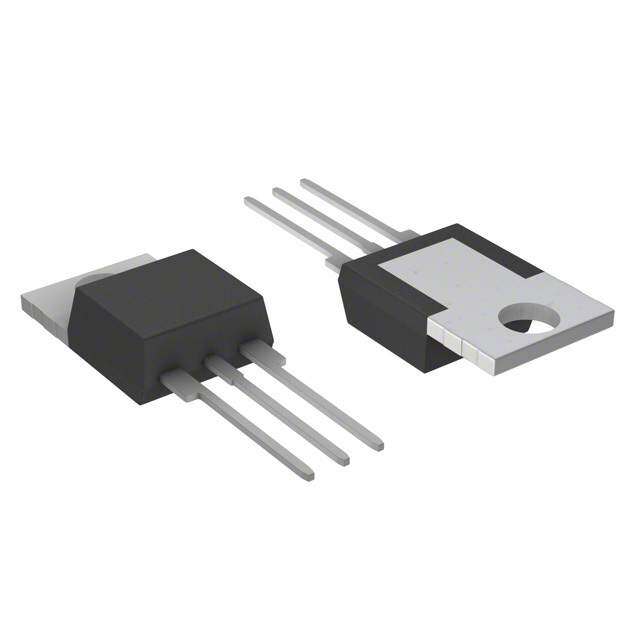
| 描述 | TRIAC ALTERNISTOR 800V 6A TO220 |
| 产品分类 | 双向可控硅 |
| 品牌 | Littelfuse Inc |
| 数据手册 | |
| 产品图片 |
|
| 产品型号 | Q8006LH4TP |
| rohs | 无铅 / 符合限制有害物质指令(RoHS)规范要求 |
| 产品系列 | - |
| 三端双向可控硅类型 | 可控硅 - 无缓冲器 |
| 供应商器件封装 | TO-220 隔离的标片 |
| 其它名称 | F5451 |
| 包装 | 管件 |
| 安装类型 | 通孔 |
| 封装/外壳 | TO-220-3 隔离片 |
| 标准包装 | 500 |
| 电压-断态 | 800V |
| 电压-栅极触发(Vgt)(最大值) | 1.3V |
| 电流-不重复浪涌50、60Hz(Itsm) | 80A,85A |
| 电流-保持(Ih)(最大值) | 35mA |
| 电流-栅极触发(Igt)(最大值) | 35mA |
| 电流-通态(It(RMS))(最大值) | 6A |
| 配置 | 单一 |


PDF Datasheet 数据手册内容提取
Thyristors 6 Amp Sensitive, Standard & Alternistor (High Commutation) Triacs Lxx06xx & Qxx06xx & Qxx06xHx Series RoHS Description This 6 Amp bidirectional solid state switch series is designed for AC switching and phase control applications such as motor speed and temperature modulation controls, lighting controls, and static switching relays. Sensitive type components guarantee gate control in Quadrants I & IV as needed for digital control circuitry. Standard type components normally operate in Quadrants I & III triggered from AC line. Alternistor type components only operate in quadrants I, II, & III and are used in circuits requiring high dv/dt capability. Features & Benefits • RoHS compliant • No contacts to wear out Agency Approval from reaction of switching • Glass – passivated events junctions Agency Agency File Number • Restricted (or limited) RFI • Voltage capability up generation, depending on E71639* to 1000 V activation point of * - L Package Only • Surge capability up sine wave to 85 A • Only requires a short gate Main Features • The L-package has activation pulse during an isolation rating of each half-cycle 2500V Symbol Value Unit RMS • UL Recognized as an • Solid-state switching Electrically Isolated I 6 A T(RMS) eliminates arcing or Semiconductor Device to VDRM/VRRM 400, 600, 800 or 1000 V contact bounce that UL 1557. I 5 to 50 mA create voltage transients GT (Q1) Applications Excellent for AC switching and phase control applications Schematic Symbol such as heating, lighting, and motor speed controls. Typical applications are AC solid-state switches, light dimmers, power tools, home/brown goods and white MT2 MT1 goods appliances. Alternistor Triacs (no snubber required) are used in applications with extremely inductive loads requiring the highest commutation performance. G Internally constructed isolated packages are offered for ease of heat sinking with highest isolation voltage. Absolute Maximum Ratings — Sensitive Triac (4 Quadrants) Symbol Parameter Value Unit I RMS on-state current (full sine wave) Lxx06Ly/Lxx06Vy/Lxx06Dy TC = 80°C 6 A T(RMS) Lxx06Ry/Lxx06Ny TC = 85°C Non repetitive surge peak on-state current f = 50 Hz t = 20 ms 50 I A TSM (full cycle, T initial = 25°C) f = 60 Hz t = 16.7 ms 60 J I2t I2t Value for fusing t = 8.3 ms 15 A2s p Critical rate of rise of on-state current di/dt f = 120 Hz T = 110°C 70 A/μs I = 50mA with 0.1µs rise time J G I Peak gate trigger current t=20μs T = 110°C 4 A GTM p J P Average gate power dissipation T = 110°C 0.4 W G(AV) J T Storage temperature range -40 to 150 °C stg T Operating junction temperature range -40 to 110 °C J Note: xx = voltage/10, y = sensitivity © 2020 Littelfuse, Inc. Specifications are subject to change without notice. Revised: 02/24/20
Thyristors 6 Amp Sensitive, Standard & Alternistor (High Commutation) Triacs Absolute Maximum Ratings — Standard Triac Symbol Parameter Value Unit Qxx06Ry / Qxx06Ny T = 95°C I RMS on-state current (full sine wave) C 6 A T(RMS) Qxx06Ly T = 90°C C Non repetitive surge peak on-state current f = 50 Hz t = 20 ms 65 I A TSM (full cycle, T initial = 25°C) f = 60 Hz t = 16.7 ms 80 J I2t I2t Value for fusing t = 8.3 ms 26.5 A2s p Critical rate of rise of on-state current di/dt f = 120 Hz T = 125°C 70 A/μs I = 200mA with 0.1µs rise time J G I Peak gate trigger current t=20μs T = 125°C 4 A GTM p J P Average gate power dissipation T = 125°C 0.5 W G(AV) J T Storage temperature range -40 to 150 °C stg T Operating junction temperature range -40 to 125 °C J Note: xx = voltage/10, y = sensitivity Absolute Maximum Ratings — Alternistor Triac (3 Quadrants) Symbol Parameter Value Unit Qxx06LHy/Qxx06VHy/Qxx06DHy T = 95°C I RMS on-state current (full sine wave) C 6 A T(RMS) Qxx06RHy/Qxx06NHy T = 100°C C Qxx06VHy 55 Qxx06DHy f = 50 Hz t = 20 ms Qxx06LHy Qxx06RHy 80 Non repetitive surge peak on-state current Qxx06NHy I A TSM (full cycle, T initial = 25°C) Qxx06VHy J 65 Qxx06DHy f = 60 Hz t = 16.7 ms Qxx06LHy Qxx06RHy 85 Qxx06NHy Qxx06VHy 17.5 Qxx06DHy I2t I2t Value for fusing t = 8.3 ms Qxx06LHy A2s p Qxx06RHy 30 Qxx06NHy di/dt Critical rate of rise of on-state current f = 120 Hz T = 125°C 70 A/μs J I Peak gate trigger current t ≤ 10 μs; I ≤ I T = 125°C 1.6 A GTM p GT GTM J P Average gate power dissipation T = 125°C 0.5 W G(AV) J T Storage temperature range -40 to 150 °C stg T Operating junction temperature range -40 to 125 °C J Note: xx = voltage/10, y = sensitivity Additional Information Datasheet Resources Samples © 2020 Littelfuse, Inc. Specifications are subject to change without notice. Revised: 02/24/20
Thyristors 6 Amp Sensitive, Standard & Alternistor (High Commutation) Triacs Electrical Characteristics (T = 25°C, unless otherwise specified) — Sensitive Triac (4 Quadrants) J Value Symbol Test Conditions Quadrant Unit Lxx06x5 Lxx06x6 Lxx06x8 I – II – III 5 5 10 I V = 12V R = 60 Ω MAX. mA GT D L IV 5 10 20 V V = 12V R = 60 Ω ALL MAX. 1.3 V GT D L V V = V R = 3.3 kΩ T = 110°C ALL MIN. 0.2 V GD D DRM L J I I = 100mA MAX. 10 10 20 mA H T 400V 30 30 40 dv/dt V = V Gate Open T = 100°C TYP. V/μs D DRM J 600V 20 20 30 (dv/dt)c (di/dt)c = 3.2 A/ms T = 110°C TYP. 1 2 2 V/μs J t I = 2 x I PW = 15µs I = 8.5 A(pk) TYP. 3.0 3.0 3.2 μs gt G GT T Electrical Characteristics (T = 25°C, unless otherwise specified) — Standard Triac J Value Symbol Test Conditions Quadrant Unit Qxx06x4 Qxx06x5 I – II – III MAX. 25 50 I V = 12V R = 60 Ω mA GT D L IV TYP. 50 75 V V = 12V R = 60 Ω I – II – III MAX. 1.3 V GT D L V V = V R = 3.3 kΩ T = 125°C ALL MIN. 0.2 V GD D DRM L J I I = 200mA MAX. 50 50 mA H T 400V 120 V = V Gate Open T = 125°C 600V 100 dv/dt D DRM J 800V MIN. 85 V/μs V = V Gate Open T = 100°C 1000V 100 D DRM J (dv/dt)c (di/dt)c = 3.2 A/ms T = 125°C TYP. 4 4 V/μs J t I = 2 x I PW = 15µs I = 8.5 A(pk) TYP. 3.0 3.0 μs gt G GT T Electrical Characteristics (T = 25°C, unless otherwise specified) — Alternistor Triac (3 Quadrants) J Value Symbol Test Conditions Quadrant Unit Qxx06xH3 Qxx06xH4 I V = 12V R = 60 Ω I – II – III MAX. 10 35 mA GT D L V V = 12V R = 60 Ω I – II – III MAX. 1.3 V GT D L V V = V R = 3.3 kΩ T = 125°C I – II – III MIN. 0.2 V GD D DRM L J I I = 100mA MAX. 15 35 mA H T 400V 75 400 Qxx06VHy / 600V 50 300 Qxx06DHy 800V 200 V = V Gate Open T = 125°C dv/dt D DRM J Qxx06LHy / MIN. 400V 75 450 V/μs Qxx06RHy / 600V 50 350 Qxx06NHy 800V 250 V = V Gate Open T = 100°C ALL 1000V 150 D DRM J (dv/dt)c (di/dt)c = 3.2 A/ms T = 125°C MIN. 20 25 V/μs J t I = 2 x I PW = 15µs I = 8.5 A(pk) TYP. 4.0 4.0 μs gt G GT T Note: xx = voltage/10, x = package, y = sensitivity © 2020 Littelfuse, Inc. Specifications are subject to change without notice. Revised: 02/24/20
Thyristors 6 Amp Sensitive, Standard & Alternistor (High Commutation) Triacs Static Characteristics Symbol Test Conditions Value Unit V I = 11.3A t = 380 µs MAX. 1.60 V TM TM p T = 25°C 400 - 600V 20 μA Lxx06xy J T = 110°C 400 - 600V 0.5 mA J T = 25°C 400 - 1000V 50 μA J Qxx06xy T = 125°C 400 - 800V 2 J mA I / I V = V T = 100°C 1000V MAX. 3 DRM RRM DRM RRM J 400 - 800V 10 T = 25°C μA J 1000V 20 Qxx06xHy T = 125°C 400 - 800V 3 J mA T = 100°C 1000V 2 J Thermal Resistances Symbol Parameter Value Unit L/Qxx06Ryy / L/Qxx06Nyy 1.8 R Junction to case (AC) L/Qxx06Lyy 3.3 °C/W Ɵ(J-C) L/Qxx06Vyy / L/Qxx06Dyy 3.2 L/Qxx06Ryy 45 R Junction to ambient L/Qxx06Lyy 50 °C/W Ɵ(J-A) L/Qxx06Vyy 70 Note: xx = voltage, x = package, y = sensitivity, yy = type & sensitivity Figure 2: Normalized DC Gate Trigger Current for Figure 1: Definition of Quadrants All Quadrants vs. Junction Temperature ALL POLARITIES ARE REFERENCED TO MT1 4.0 MT2 POSITIVE MT2 (Positive +Half Cycle) MT2 (-)GIGATTE (+)IGGATTE 5°C) 3.0 2 MT1 MT1 IGT T = J IGT - RMETF2 QQIIIII QQIIV RMETF2 + IGT Ratio ofI(GT 21..00 (-)IGT (+)IGT GATE GATE MT1 MT1 0.0 - -65 -40 -15 10 35 60 85 110 125 REF MT2 NEGATIVE REF (Negative Half Cycle) Junction Temperature (TJ)- °C NOTE: Alternistors will not operate in QIV Note: Alternistors will not operate in QIV © 2020 Littelfuse, Inc. Specifications are subject to change without notice. Revised: 02/24/20
Thyristors 6 Amp Sensitive, Standard & Alternistor (High Commutation) Triacs Figure 3: Normalized DC Holding Current Figure 4: Normalized DC Gate Trigger Voltage for vs. Junction Temperature All Quadrants vs. Junction Temperature 4.0 2.0 C) 3.0 5°C) 1.5 IH I(T = 25°H J 2.0 VGT V(T = 2GT J 1.0 Ratio of 1.0 Ratio of 0.5 0.0 0.0 -65 -40 -15 10 35 60 85 110 125 -65 -40 -40 10 35 60 85 110 125 Junction Temperature (T)- °C Junction Temperature (T)- ºC J J Figure 5: Power Dissipation (Typical) Figure 6: Maximum Allowable Case Temperature vs. RMS On-State Current vs. On-State Current (Sensitive Triac) 18 e 120 n ur atio 16 erat 110 sip 14 mp Average On-State Power Dis(P) - WattsD(AV)11246802 CCLOUOARNDRD:EU NRCTeTs WIiOsAtNiVv AEeN FoOGr RLInMEd: :u 3 cS6tii0nv°uesoidal aximum Allowable Case Te(T) - °CC109870000 CLCCOUOAASRNDERD :TEU RENCeMTTs WPiIsOEt ALNLLiRvVxxxA eAxxxET 000NoFU666OrG LRVDIRLnyEyyMEd: :uM :3 cS6etii0anv°sueusroeidd aals shown Lxx06Ry M on Dimensional Drawings 0 60 0 2 4 6 8 10 12 14 16 0 1 2 3 4 5 6 7 RMS On-State Current (IT(RMS)) - Amps RMS On-State Current (IT(RMS)) - Amps Figure 7: Maximum Allowable Case Temperature Figure 8: Maximum Allowable Case Temperature vs. On-State Current (Standard Triac) vs. On-State Current (Alternistor Triac) 130 130 wable Case Temperature (T) - °CC11102910000 Qxx06Ly QQxxxx0066NRyy wable Case Temperature(T) - °CC11102910000 QQQxxxxxx000666LVDHHHyyy QQxxxx0066RNHHyy Maximum Allo 8700 CLCCoOnUOA ASRNDDERDim :TEU RENeCeMnTTss WPiIisOoEtAnNiRvVaA eAlET DNoFUOrrG aRIRLnwEMEd:i :nuM :3 gcS6etsii0anv°sueusroeidd aals shown Maximum Allo 8700 CLCCoOnUOA ASRNDDERiDm :TEU RENeCeMnTTss WPiIisOoEtAnNiRvVaA eAlET DNoFUOrrG aRIRLnwEMEd:i :nuM :3 gcS6etsii0anv°sueusroeidd aals shown 60 60 0 1 2 3 4 5 6 7 0 1 2 3 4 5 6 7 RMS On-State Current (I ) - Amps RMS On-State Current (I ) - Amps T(RMS) T(RMS) © 2020 Littelfuse, Inc. Specifications are subject to change without notice. Revised: 02/24/20
Thyristors 6 Amp Sensitive, Standard & Alternistor (High Commutation) Triacs Figure 9: Maximum Allowable Ambient Temperature Figure 10: Maximum Allowable Ambient Temperature vs. On-State Current (Sensitive / Standard Triac) vs. On-State Current (Alternistor Triac) 120 120 Maximum Allowable Ambient Temperature (T) - °CA108640000 CLCOUOARNDRD:EU RNCeTTs WiILsOt/ANiQvV eAxE xNoF0OrG 6IRLnVMEdy:u :3 cS6tii0nv°uesoidal LLxxxx0066RLyy QQQxxxxxx000666NRLyyy Maximum Allowable ) - °CAmbient Temperature (TA108640000 CLCCOUOAASRNDERD :TEU RENCeMTTs WPiIsOEQtANiRvxVA exAET 0NoF6UOrGV RIRHLnEMEdy: :uM :3 cS6etii0anv°sueusroeidd aals shown QQQxxxxxx000666NRLHHHyyy FREE AIR RATING – NO HEATSINK on Dimensional Drawing 20 20 0.0 0.2 0.4 0.6 0.8 1.0 1.2 1.4 1.6 1.8 2.0 0.0 0.2 0.4 0.6 0.8 1.0 1.2 1.4 1.6 1.8 2.0 RMS On-State Current (IT(RMS)) - Amps RMS On-State Current [IT(RMS)] - Amps Figure 11: On-State Current vs. On-State Voltage (Typical) 20 us 18 TC = 25°C o neps 16 am ntA 14 Negative Instae Current (i) - T 11208 ostitive or On-Stat 642 P 0 0.7 0.8 0.9 1.0 1.1 1.2 1.3 1.4 1.5 1.6 Postitive or Negative Instantaneous On-State Voltage (v) - Volts T © 2020 Littelfuse, Inc. Specifications are subject to change without notice. Revised: 02/24/20
Thyristors 6 Amp Sensitive, Standard & Alternistor (High Commutation) Triacs Figure 12: Surge Peak On-State Current vs. Number of Cycles (Sensitive / Standard Triac) 100 SUPPLY FREQUENCY: 60 Hz Sinusoidal LOAD: Resistive Qxx06Ly Qxx06Ry RMS On-State Current: [I ]: Maximum Rated ve) mps Qxx06Ny Value at Specified Case TTe(RmMSp)erature Surge (Non-Repetitiate Current (I) - ATSM10 LLLLxxxxxxxx00006666VDRLyyyy N12..o Gf Otrtoeaeavtlmsleteo:edprw l ecoviornaaandgltut umrserou.ealr ymgh eana soyc t urb erberteeu l nrornets eptind edt aetuotrrev insdatg le.u aanndtidyl - jsiumtnamctetei o dnia tely eak n-St PO 1 1 10 100 1000 Surge Current Duration- Full Cycles Figure 13: Surge Peak On-State Current vs. Number of Cycles (Alternistor Triac) 100 SUPPLY FREQUENCY: 60 Hz Sinusoidal Qxx06LHy Qxx06RHy LOAD: Resistive Qxx06NHy RMS On-State Current: [I ]: Maximum Rated T(RMS) ve) mps Value at Specified Case Temperature Surge (Non-Repetitiate Current (I) - ATSM10 QQxxxx0066VDHHyy N12..o Gf Otrtoeaeavtlmsleteo:edprw l ecoviornaaandgltut umrserou.ealr ymgh eana soyc t urb erberteeu l nrornets eptind edt aetuotrrev insdatg le.u aanndtidyl - jsiumtnamctetei o dnia tely eak n-St PO 1 1 10 100 1000 Surge Current Duration- Full Cycles Note: xx = voltage/10, x = package, y = sensitivity, © 2020 Littelfuse, Inc. Specifications are subject to change without notice. Revised: 02/24/20
Thyristors 6 Amp Sensitive, Standard & Alternistor (High Commutation) Triacs Soldering Parameters Reflow Condition Pb – Free assembly t - Temperature Min (T ) 150°C P s(min) TP Pre Heat - Temperature Max (T ) 200°C s(max) RRaammpp--uupp e Average ramp- u Tpim raet e(m (Liniq tuoi dmuasx T)e m(tsp)) (TL) to peak 650°C –/ s1e8c0o nsde cmsax rutare TS(mTaxL) tL TS(max) to TL - Ramp-up Rate 5°C/second max pm PPrreehheeaatt RRaammpp--ddoown Reflow - Temperature (TL) (Liquidus) 217°C eT TS(min) - Temperature (tL) 60 – 150 seconds tS Peak Temperature (T) 260+0/-5 °C P Time within 5°C of actual peak Temperature (t) 20 – 40 seconds 25 p time to peak temperature Ramp-down Rate 5°C/second max Time Time 25°C to peak Temperature (T) 8 minutes Max. P Do not exceed 280°C Physical Specifications Environmental Specifications Terminal Finish 100% Matte Tin-plated Test Specifications and Conditions UL Recognized compound meeting flammability Body Material rating V-0 MIL-STD-750, M-1040, Cond A Applied Peak AC AC Blocking (V ) Terminal Material Copper Alloy DRM voltage @ 125°C for 1008 hours MIL-STD-750, M-1051, Temperature Cycling 100 cycles; -40°C to +150°C; 15-min dwell-time EIA / JEDEC, JESD22-A101 Temperature/Humidity Design Considerations 1008 hours; 320V - DC: 85°C; 85% rel humidity High Temp Storage MIL-STD-750, M-1031, 1008 hours; 150°C Careful selection of the correct components for the application’s operating Low-Temp Storage 1008 hours; -40°C parameters and environment will go a long way toward extending the operating life of the Thyristor. Good design practice should limit the Resistance to Solder Heat MIL-STD-750 Method 2031 maximum continuous current through the main terminals to 75% of the Solderability ANSI/J-STD-002, category 3, Test A components rating. Other ways to ensure long life for a power discrete Lead Bend MIL-STD-750, M-2036 Cond E semiconductor are proper heat sinking and selection of voltage ratings for worst case conditions. Overheating, overvoltage (including dv/dt), and surge currents are the main killers of semiconductors. Correct mounting, soldering, and forming of the leads also help protect against component damage. © 2020 Littelfuse, Inc. Specifications are subject to change without notice. Revised: 02/24/20
Thyristors 6 Amp Sensitive, Standard & Alternistor (High Commutation) Triacs Dimensions — TO-220AB (R-Package) — Non-Isolated Mounting Tab Common with Center Lead T MEASURING POINT AREA (REF.) 0.17 IN2 Inches Millimeters C Dimension O Min Max Min Max ØE A P .83.2103 A 0.380 0.420 9.65 10.67 MT2 B 0.105 0.115 2.67 2.92 B C 0.230 0.250 5.84 6.35 C D 0.590 0.620 14.99 15.75 13.36 E 0.142 0.147 3.61 3.73 D .526 F 0.110 0.130 2.79 3.30 7.01 G 0.540 0.575 13.72 14.61 .276 H 0.025 0.035 0.64 0.89 J 0.195 0.205 4.95 5.21 K 0.095 0.105 2.41 2.67 F NGAOTTEC HLE IAND L 0.060 0.075 1.52 1.91 TO ID. M 0.085 0.095 2.16 2.41 NON-ISOLATED N 0.018 0.024 0.46 0.61 R TAB G O 0.178 0.188 4.52 4.78 L P 0.045 0.060 1.14 1.52 H R 0.038 0.048 0.97 1.22 K N J M Note: Maximum torque to MT1 MT2 GATE be applied to mounting tab is 8 in-lbs, (0.904 Nm). Dimensions — TO-220AB (L-Package) — Isolated Mounting Tab T MEASURING POINT AREA (REF.) 0.17 IN2 Inches Millimeters C Dimension O Min Max Min Max ØE A P .83.2130 A 0.380 0.420 9.65 10.67 B 0.105 0.115 2.67 2.92 B C 0.230 0.250 5.84 6.35 C D 0.590 0.620 14.99 15.75 13.36 E 0.142 0.147 3.61 3.73 D .526 F 0.110 0.130 2.79 3.30 7.01 G 0.540 0.575 13.72 14.61 .276 H 0.025 0.035 0.64 0.89 J 0.195 0.205 4.95 5.21 K 0.095 0.105 2.41 2.67 F L 0.060 0.075 1.52 1.91 M 0.085 0.095 2.16 2.41 N 0.018 0.024 0.46 0.61 R G O 0.178 0.188 4.52 4.78 L P 0.045 0.060 1.14 1.52 H R 0.038 0.048 0.97 1.22 K N Note: Maximum torque to J M be applied to mounting tab MT1 MT2GATE is 8 in-lbs, (0.904 Nm). © 2020 Littelfuse, Inc. Specifications are subject to change without notice. Revised: 02/24/20
Thyristors 6 Amp Sensitive, Standard & Alternistor (High Commutation) Triacs Dimensions — TO-263AB (N-Package) — D2-PAK Surface Mount Inches Millimeters TC MEASURING POINT AREA: 0.11 IN2 Dimension Min Max Min Max B V C MT2 E A 0.360 0.370 9.14 9.40 B 0.380 0.420 9.65 10.67 C 0.178 0.188 4.52 4.78 8.41 7.01 .331 D 0.025 0.035 0.64 0.89 A .276 E 0.045 0.060 1.14 1.52 S F 0.060 0.075 1.52 1.91 G 0.095 0.105 2.41 2.67 W U H 0.092 0.102 2.34 2.59 MT1 GATE K J J 0.018 0.024 0.46 0.61 K 0.090 0.110 2.29 2.79 G D H .83.2103 S 0.590 0.625 14.99 15.88 F V 0.035 0.045 0.89 1.14 U 0.002 0.010 0.05 0.25 11.68 2.16 .460 .085 W 0.040 0.070 1.02 1.78 7.01 7.01 .276 .276 16.89 .665 8.89 1.40 .350 .055 3.81 .150 2.03 .080 6.60 .260 Dimensions — TO-251AA (V-Package) — V-PAK Through Hole T MEASURING POINT AREA: 0.040 IN2 Inches Millimeters C Dimension Min Typ Max Min Typ Max MT2 E H 5.28 A 0.037 0.040 0.043 0.94 1.01 1.09 D J .208 B 0.235 0.242 0.245 5.97 6.15 6.22 C 0.350 0.361 0.375 8.89 9.18 9.53 D 0.205 0.208 0.213 5.21 5.29 5.41 A E 0.255 0.262 0.265 6.48 6.66 6.73 5.34 F 0.027 0.031 0.033 0.69 0.80 0.84 .210 G 0.087 0.090 0.093 2.21 2.28 2.36 B H 0.085 0.092 0.095 2.16 2.34 2.41 I 0.176 0.180 0.184 4.47 4.57 4.67 J 0.018 0.020 0.023 0.46 0.51 0.58 P R S K 0.035 0.037 0.039 0.90 0.95 1.00 Q L 0.018 0.020 0.023 0.46 0.52 0.58 K P 0.042 0.047 0.052 1.06 1.20 1.32 Q 0.034 0.039 0.044 0.86 1.00 1.11 C R 0.034 0.039 0.044 0.86 1.00 1.11 S 0.074 0.079 0.084 1.86 2.00 2.11 MT1 L F MT2 G GATE I © 2020 Littelfuse, Inc. Specifications are subject to change without notice. Revised: 02/24/20
Thyristors 6 Amp Sensitive, Standard & Alternistor (High Commutation) Triacs Dimensions — TO-252AA (D-Package) — D-PAK Surface mount MT2 DE TC MEASURING POINT .52.0288 .62.6741 Dimension Min InTcyhpes Max Min MilliTmypeters Max A 0.037 0.040 0.043 0.94 1.01 1.09 A B 0.235 0.243 0.245 5.97 6.16 6.22 .52.1304 .62.6741 C 0.106 0.108 0.113 2.69 2.74 2.87 B D 0.205 0.208 0.213 5.21 5.29 5.41 E 0.255 0.262 0.265 6.48 6.65 6.73 1.60 F 0.027 0.031 0.033 0.69 0.80 0.84 P .063 G 0.087 0.090 0.093 2.21 2.28 2.36 C Q 1.80 H 0.085 0.092 0.095 2.16 2.33 2.41 MT1 GATEF AREA: 0.040 IN2 .071 I 0.176 0.179 0.184 4.47 4.55 4.67 MT2 G .1138 .41.8610 KJ 00..001385 00..002307 00..002339 00..4960 00..5915 01..0508 I L 0.018 0.020 0.023 0.46 0.51 0.58 M 0.000 0.000 0.004 0.00 0.00 0.10 O L N 0.021 0.026 0.027 0.53 0.67 0.69 K J H O 0° 0° 5° 0° 0° 5° M P 0.042 0.047 0.052 1.06 1.20 1.32 N Q 0.034 0.039 0.044 0.86 1.00 1.11 © 2020 Littelfuse, Inc. Specifications are subject to change without notice. Revised: 02/24/20
Thyristors 6 Amp Sensitive, Standard & Alternistor (High Commutation) Triacs Product Selector Voltage Gate Sensitivity Quadrants Part Number Type Package 400V 600V 800V 1000V I - II - III IV Lxx06L5 X X - - 5 mA 5 mA Sensitive Triac TO-220L Lxx06D5 X X - - 5 mA 5 mA Sensitive Triac TO-252 D-PAK Lxx06R5 X X - - 5mA 5mA Sensitive Triac TO-220R Lxx06V5 X X - - 5 mA 5 mA Sensitive Triac TO-251 V-PAK Lxx06L6 X X - - 5 mA 10 mA Sensitive Triac TO-220L Lxx06D6 X X - - 5 mA 10 mA Sensitive Triac TO-252 D-PAK Lxx06R6 X X - - 5mA 10mA Sensitive Triac TO-220R Lxx06V6 X X - - 5 mA 10 mA Sensitive Triac TO-251 V-PAK Lxx06L8 X X - - 10 mA 20 mA Sensitive Triac TO-220L Lxx06D8 X X - - 10 mA 20 mA Sensitive Triac TO-252 D-PAK Lxx06R8 X X - - 10mA 20mA Sensitive Triac TO-220R Lxx06V8 X X - - 10 mA 20 mA Sensitive Triac TO-251 V-PAK Qxx06VH3 X X - - 10 mA - Alternistor Triac TO-251 V-PAK Qxx06DH3 X X - - 10 mA - Alternistor Triac TO-252 D-PAK Qxx06L4 X - - - 25 mA - Standard Triac TO-220L Qxx06R4 X - - - 25 mA - Standard Triac TO-220R Qxx06N4 X - - - 25 mA - Standard Triac TO-263 D²-PAK Qxx06LH3 X X - - 10mA - Alternistor Triac TO-220L Qxx06RH3 X X - - 10mA - Alternistor Triac TO-220R Qxx06LH4 X X X X 35 mA - Alternistor Triac TO-220L Qxx06RH4 X X X X 35 mA - Alternistor Triac TO-220R Qxx06VH4 X X X X 35 mA - Alternistor Triac TO-251 V-PAK Qxx06DH4 X X X X 35 mA - Alternistor Triac TO-252 D-PAK Qxx06NH4 X X X X 35 mA - Alternistor Triac TO-263 D²-PAK Qxx06L5 - X X X 50 mA - Standard Triac TO-220L Qxx06R5 - X X X 50 mA - Standard Triac TO-220R Qxx06N5 - X X X 50 mA - Standard Triac TO-263 D²-PAK Packing Options Part Number Marking Weight Packing Mode Base Quantity Lxx06L/RyTP Lxx06L/Ry 2.2 g Tube Pack 500 (50 per tube) Lxx06DyTP Lxx06Dy 0.3 g Tube 750 (75 per tube) Lxx06DyRP Lxx06Dy 0.3 g Embossed Carrier 2500 Lxx06VyTP Lxx06Vy 0.4 g Tube 750 (75 per tube) Qxx06L/RyyTP Qxx06L/Ryy 2.2 g Tube Pack 500 (50 per tube) Qxx06NyyTP Qxx06Nyy 1.6 g Tube 500 (50 per tube) Qxx06NyyRP Qxx06Nyy 1.6 g Embossed Carrier 500 Qxx06DyyTP Qxx06Dyy 0.3 g Tube 750 (75 per tube) Qxx06DyyRP Qxx06Dyy 0.3 g Embossed Carrier 2500 Qxx06VyyTP Qxx06Vyy 0.4 g Tube 750 (75 per tube) Note: xx = voltage/10; yy = sensitivity © 2020 Littelfuse, Inc. Specifications are subject to change without notice. Revised: 02/24/20
Thyristors 6 Amp Sensitive, Standard & Alternistor (High Commutation) Triacs TO-252 Embossed Carrier Reel Pack (RP) Specifications Meets all EIA-481-2 Standards 0.157 (4.0) 0.059 DIA (1.5) Gate MT1 (01.66.30) (01.532.34)* XXXXXX XXDC XXXXXX XXDC XXXXXX XXDC XXXXXX * Cover tape 0.315 MT2 (8.0) 12.99 0.512 (13.0) Arbor (330.0) Dimensions Hole Dia. are in inches (and millimeters). 0.64 (16.3) Direction of Feed TO-263 Embossed Carrier Reel Pack (RP) Specifications Meets all EIA-481-2 Standards 0.63 0.157 (16.0) (4.0) Gate 0.059 DIA (1.5) MT1 0.945 0.827 * (24.0) (21.0) * Cover tape MT2 12.99 0.512 (13.0) Arbor (330.0) Hole Dia. Dimensions are in inches (and millimeters). 1.01 (25.7) Direction of Feed © 2020 Littelfuse, Inc. Specifications are subject to change without notice. Revised: 02/24/20
Thyristors 6 Amp Sensitive, Standard & Alternistor (High Commutation) Triacs Part Numbering System Part Marking System Q 60 06 L H4 56 TO-251AA- (V Package) TO-252AA- (D Package) Component Type Lead from Dimensions L : Sensitive Triac xx : Lead Form Option L6006V5 L6006V5 Q : Triac or Alternistor Voltage Rating Sensitivity & Type 40 : 400V Sensitive Triac: 60 : 600V 3 : 3 mA (QI, II, III, IV) 80 : 800V 5 : 5 mA (QI, II, III, IV) YMLDD ® YMLDD ® K0 : 1000V 6 : 5 mA (QI, II, III) 10 mA (QIV) Date Code Marking Current 8 : 10 mA (QI, II, III) Y:Year Code 06: 6A 20 mA (QIV) M: Month Code L: Location Code Standard Triac: DD: Calendar Code 4 : 25 mA (QI, II, III) Package Type 5 : 50 mA (QI, II, III) L : TO-220 Isolated Alternistor Triac: R : TO-220 Non-Isolated H3 : 10 mA (QI, II, III) TO-220 AB - (L and R Package) N : TO-263 (D2PAK) H4 : 35 mA (QI, II, III) TO-263 AB - (N Package) V : TO-251 (VPAK) D : TO-252 (DPAK) ® Q6006R5 YM ® Date Code Marking Y:Year Code M: Month Code XXX: Lot Trace Code ® Disclaimer Notice - Information furnished is believed to be accurate and reliable. However, users should independently evaluate the suitability of and test each product selected for their own applications. Littelfuse products are not designed for, and may not be used in, all applications. Read complete Disclaimer Notice at www.littelfuse.com/disclaimer-electronics. © 2020 Littelfuse, Inc. Specifications are subject to change without notice. Revised: 02/24/20