ICGOO在线商城 > 集成电路(IC) > PMIC - 稳压器 - 线性 > PQ1R28J0000H
 Datasheet下载
- 型号: PQ1R28J0000H
- 制造商: Sharp Microelectronics
- 库位|库存: xxxx|xxxx
- 要求:
| 数量阶梯 | 香港交货 | 国内含税 |
| +xxxx | $xxxx | ¥xxxx |
查看当月历史价格
查看今年历史价格
PQ1R28J0000H产品简介:
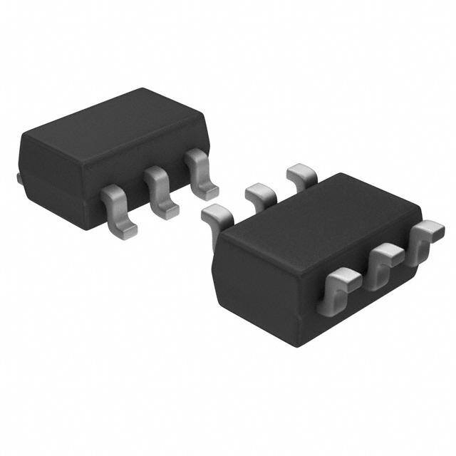
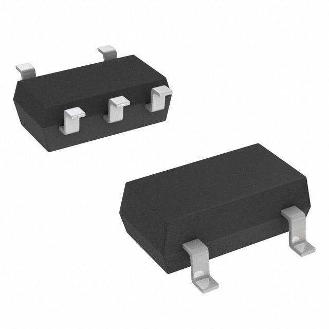
ICGOO电子元器件商城为您提供PQ1R28J0000H由Sharp Microelectronics设计生产,在icgoo商城现货销售,并且可以通过原厂、代理商等渠道进行代购。 PQ1R28J0000H价格参考。Sharp MicroelectronicsPQ1R28J0000H封装/规格:PMIC - 稳压器 - 线性, Linear Voltage Regulator IC Positive Fixed 1 Output 2.8V 150mA SOT-23L-6。您可以下载PQ1R28J0000H参考资料、Datasheet数据手册功能说明书,资料中有PQ1R28J0000H 详细功能的应用电路图电压和使用方法及教程。
Sharp Microelectronics品牌的PQ1R28J0000H属于线性稳压器类的电源管理集成电路(PMIC),主要用于需要稳定电压输出的电子设备中。该器件具备较高的电压精度和良好的负载/线路调整率,适合用于对电源稳定性要求较高的场景。

其主要应用场景包括:

1. 便携式电子产品:如智能手机、平板电脑、数码相机等,用于为处理器、传感器或其他低电压电路提供稳定电源。
2. 消费类电子设备:如机顶盒、DVD播放器、音响设备等,作为系统内部的多路电源管理组件。
3. 工业控制设备:如PLC、工业仪表、自动化设备,用于为敏感的模拟或数字电路提供干净稳定的电压。
4. 通信模块:如无线通信模块(Wi-Fi、蓝牙、蜂窝模块)的电源管理部分,确保射频性能稳定。
5. 汽车电子系统:例如车载导航、娱乐系统、仪表盘控制模块等,适用于对电源噪声敏感的环境。

该线性稳压器具有低静态电流、高纹波抑制比(PSRR)等特性,适合用于电池供电系统中,有助于延长设备的续航时间并提升整体能效。
| 参数 | 数值 |
| 产品目录 | 集成电路 (IC) |
| 描述 | IC REG LDO 2.8V 0.15A SOT23L-6 |
| 产品分类 | |
| 品牌 | Sharp Microelectronics |
| 数据手册 | |
| 产品图片 |
|
| 产品型号 | PQ1R28J0000H |
| rohs | 无铅 / 符合限制有害物质指令(RoHS)规范要求 |
| 产品系列 | - |
| 产品目录页面 | |
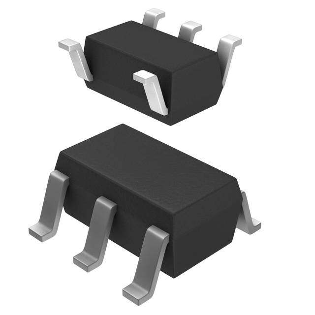
| 供应商器件封装 | SOT-23L-6 |
| 其它名称 | 425-2316-1 |
| 包装 | 剪切带 (CT) |
| 安装类型 | 表面贴装 |
| 封装/外壳 | SOT-23-6 |
| 工作温度 | -30°C ~ 80°C |
| 标准包装 | 1 |
| 电压-跌落(典型值) | 0.29V @ 150mA |
| 电压-输入 | 最高 16V |
| 电压-输出 | 2.8V |
| 电流-输出 | 150mA |
| 电流-限制(最小值) | - |
| 稳压器拓扑 | 正,固定式 |
| 稳压器数 | 1 |


- 商务部:美国ITC正式对集成电路等产品启动337调查
- 曝三星4nm工艺存在良率问题 高通将骁龙8 Gen1或转产台积电
- 太阳诱电将投资9.5亿元在常州建新厂生产MLCC 预计2023年完工
- 英特尔发布欧洲新工厂建设计划 深化IDM 2.0 战略
- 台积电先进制程称霸业界 有大客户加持明年业绩稳了
- 达到5530亿美元!SIA预计今年全球半导体销售额将创下新高
- 英特尔拟将自动驾驶子公司Mobileye上市 估值或超500亿美元
- 三星加码芯片和SET,合并消费电子和移动部门,撤换高东真等 CEO
- 三星电子宣布重大人事变动 还合并消费电子和移动部门
- 海关总署:前11个月进口集成电路产品价值2.52万亿元 增长14.8%


PDF Datasheet 数据手册内容提取
Low Power-Loss Voltage Regulators PQ1R30 Series PQ1R30 Series Low Output Current, Compact Surface Mount Type Low Power-Loss Voltage Regulators (cid:1) Features (cid:1) Outline Dimensions (Unit : mm) (cid:3) Compact surface mount package(3.4 x 2.2 x 1.2mm) 6 5 4 (cid:3) Low power-loss (Dropout voltage: TYP.0.16V/MAX. 0.26V at Io=60mA) 1 R 3 0 (cid:3) High ripple rejection(TYP.55dB) (cid:3) Low current operation type (Dissipation current at no load: TYP. 170µA) 1 2 3 6–0.32±0.1 ( ) :Typical dimensions (cid:3) Built-in ON/OFF control function (0.95)(0.95) (Dissipation current at OFF-state: MAX. 0.1µA) (cid:3) Overcurrent, overheat protection functions 3.8MAX (cid:1) Applications (3.4) (0.3) 2.2±0.2 (cid:3)(cid:3)(cid:3)(cid:3) CPCCeoaermlrlsduoellenraasrass lp /iphnChofaoonmrnemescsoadtieorns tools(PDA) 1.4MAX ±1.20.20~0.1±0.150.1 0.2M3I.N3±00..23MIN 15 MAX˚ (cid:3) PCMCIA cards for notebook PCs (cid:1) Model Line-ups Internal connection diagram Output Voltage Model No. Output Voltage Model No. 6 4 2.2V PQ1R22 3.4V PQ1R34 1 ON/OFF control terminal(Vc) 2.5V PQ1R25 3.6V PQ1R36 2 5 GND 2.7V PQ1R27 3.8V PQ1R38 Specific IC 34 DNCoi soeu rtpeudtu (cVtioo)n (Nr) 2.8V PQ1R28 4.0V PQ1R40 1 3 6 DC input (VIN) 2.9V PQ1R29 4.7V PQ1R47 2 5 3.0V PQ1R30 4.9V PQ1R49 3.1V PQ1R31 5.0V PQ1R50 3.3V PQ1R33 5.2V PQ1R52 ❇ It is available for every 0.1V(1.8V to 5.5V) (cid:1) Absolute Maximum Ratings (Ta=25˚C) Parameter Symbol Rating Unit ❇1Input voltage VIN 16 V ❇1ON/OFF control terminal voltage Vc 16 V Output current Io 240 mA ❇2Power dissipation PD 400 mW ❇3Junction temperature Tj 150 ˚C Operating temperature Topr –30 to +80 ˚C Storage temperature Tstg –55 to +150 ˚C Soldering temperature Tsol 260 (For 10s) ˚C ❇1 All are open except GND and applicable terminals. ❇2 At mounted on PCB ❇3 Overheat protection may operate at 125<=Tj<=150˚C. • Please refer to the chapter " Handling Precautions ". Notice In the absence of confirmation by device specification sheets,SHARP takes no responsibility for any defects that may occur in equipment using any SHARP devices shown in catalogs,data books,etc.Contact SHARP in order to obtain the latest device specification sheets before using any SHARP device. Internet Internet address for Electronic Components Group http://sharp-world.com/ecg/
Low Power-Loss Voltage Regulators PQ1R30 Series (cid:1) Electrical Characteristics (Unless otherwise specified, ❇4 Io=30mA, Vc=1.8V, Ta=25˚C) Parameter Symbol Conditions MIN. TYP. MAX. Unit Output voltage VO –– Refer to the following table. V Output current IO ❇5 180 240 –– mA Recommended output current –– –– –– –– 150 mA IO=5mA to 60mA –– 10 50 Load regulation RegL IO=5mA to 100mA –– 20 100 mV IO=5mA to 150mA –– 40 160 Line regulation RegI Vi=VO(TYP)+1V to VO(TYP)+6V –– 3.0 20 mV Temperature coefficient of output voltage TCVO IO=10mA, Tj=–25 to +75˚C –– 0.05 –– mV/˚C Ripple rejection RR –– –– 55 –– dB Output noise voltage Vno(rms) 10Hz<f<100kHz, Cn=0.1µF, IO=30mA Refer to the following table. µV Dropout voltage Vi-O(1) IO=60mA, ❇6 –– 0.16 0.26 V Vi-O(2) IO=150mA, ❇6 –– 0.29 0.4 ❇7ON-state voltage for control VC(ON) –– 1.8 –– –– V ON-state current for control IC(ON) VC=1.8V –– 12 30 µA OFF-state voltage for control VC(OFF) –– –– –– 0.6 V Quiescent current Iq IO=0mA –– 170 350 µA Output OFF-state dissipation current Iqs VIN=8V, VC=0.4V –– –– 0.1 µA Response time(Rise time) Tr IO=30mA, VC=0➝1.8V –– 0.3 –– ms Noise control terminal voltage –– –– –– 1.25 –– V ❇4 VIN=Vo (TYP)+1.0V ❇5 Output current shall be the value when output voltage lowers 0.3V from the voltage at Io=30mA. ❇6 Dropout voltage when output voltage lowers 5% from the voltage at VIN=Vo+1V. ❇7 In case that the control terminal 1 is non-connection, output voltage should be OFF-state. ❇8 In case of PQ1R13, PQ1R15, PQ1R18, VIN minimum=2.3V (cid:1) Output Voltage Line-ups (cid:1) Output Noise Voltage Line-ups (VIN=Vo(TYP)+1.0V, Io=30mA, Vc=1.8V, Ta=25˚C) (VIN=Vo(TYP)+1.0V, Io=30mA, Vc=1.8V, Cn=0.1µF, 10Hz<f<100kHz, Ta=25˚C) Model No. Symbol MIN. TYP. MAX. Unit Model No. Symbol MIN. TYP. MAX. Unit PQ1R13 1.220 1.3 1.380 PQ1R13 –– 15 –– PQ1R15 1.420 1.5 1.580 PQ1R15 –– 30 –– PQ1R18 1.720 1.8 1.800 PQ1R18 –– 15 –– PQ1R22 2.120 2.2 2.280 PQ1R22 –– 20 –– PQ1R25 2.420 2.5 2.580 PQ1R25 –– 25 –– PQ1R27 2.620 2.7 2.780 PQ1R27 –– 25 –– PQ1R28 2.720 2.8 2.880 PQ1R28 –– 25 –– PQ1R29 2.820 2.9 2.980 PQ1R29 –– 25 –– PQ1R30 2.920 3.0 3.080 PQ1R30 –– 30 –– PQ1R31 3.020 3.1 3.180 PQ1R31 –– 30 –– PQ1R32 3.120 3.2 3.280 PQ1R32 –– 30 –– PQ1R33 VO 3.215 3.3 3.385 V PQ1R33 Vno(rms) –– 30 –– µV PQ1R34 3.315 3.4 3.485 PQ1R34 –– 30 –– PQ1R35 3.410 3.5 3.590 PQ1R35 –– 40 –– PQ1R36 3.510 3.6 3.690 PQ1R36 –– 35 –– PQ1R37 3.605 3.7 3.795 PQ1R37 –– 30 –– PQ1R38 3.705 3.8 3.895 PQ1R38 –– 35 –– PQ1R40 3.900 4.0 4.100 PQ1R40 –– 40 –– PQ1R42 4.095 4.2 4.305 PQ1R42 –– 30 –– PQ1R47 4.580 4.7 4.820 PQ1R47 –– 45 –– PQ1R49 4.775 4.9 5.025 PQ1R49 –– 45 –– PQ1R50 4.875 5.0 5.125 PQ1R50 –– 50 –– PQ1R52 5.070 5.2 5.330 PQ1R52 –– 50 ––
Low Power-Loss Voltage Regulators PQ1R30 Series Fig. 1 Test Circuit Fig. 2 Test Circuit of Ripple Rejection + 6 4 6 4 AIVqI,N Iqs 1+µF AIc(1ON) 2 5 3 0.1µF 1+0µFARLIOVVO VINei 1+µF V1c 2 5 3 0.1µF 1+0µF RL V eo Vc f=400Hz(sine wave) ei(rms)=100mV VIN=Vo(TYP)+1.0V Io=10mA RR=20 log(ei(rms)/eo(rms)) Fig. 3 Power Dissipation vs. Ambient Fig. 4 Overcurrent Protection Characteristics Temperature (Typical Value) 500 100 W)400 PD %) 80 m e ( (D ag ssipation P320000 output volt 4600 di e Power 100 Relativ 20 0 0 –20 0 50 80 100 150 0 0.1 0.2 0.3 0.4 Ambient temperature Ta (˚C) Output current IO (A) Note)Oblique line portion : Overheat protection may operate in this area. Note)Oblique line portion : Overheat protection may operate in this area. Fig. 5 Output Voltage Deviation vs. Junction Fig. 6 Output Voltage vs. Input Voltage Temperature (PQ1R30) (Typical Value) (PQ1R30) (Typical Value) 80 4.0 (mV)O 60 ICVVOICO=N==1=1104.0m8.0µVVAF CCION==110µµFF ∆n V 40 o(V) 3.0 RL=∞ ut voltage deviatio––2420000 Output voltage V 21..00 RL=R2L0=Ω40Ω utp–60 O –80 0 –40–20 0 20 40 60 80 100120140 0 1.0 2.0 3.0 4.0 5.0 6.0 Junction temperature Tj (˚C) Input voltage VIN(V)
Low Power-Loss Voltage Regulators PQ1R30 Series Fig. 7 Circuit Operating Current vs. Input Fig. 8 Dropout Voltage vs. Junction Voltage (PQ1R30) (Typical Value) Temperature (PQ1R30) (Typical Value) 10.0 0.4 mA) 9.0 CCION==110µµFF 0.35 VIN : Voltage when output voltage is 95% ( rent Ibias 786...000 RL=20Ω e Vi-o (V)0.02.53 Vi-o(2) : Io=150mA r g g cu 5.0 olta 0.2 eratin 43..00 pout v0.15 Vi-o(1) : Io=60mA uit op 2.0 RL=40Ω Dro0.00.51 Circ 1.0 RL=∞ 0 0 0 5.0 10.0 15.0 –40–20 0 20 40 60 80 100120140 Input voltage VIN (V) Junction temperature Tj (˚C) Fig. 9 Quiescent Current vs. Junction Fig.10 Ripple Rejection vs. Input Ripple Temperature Frequency 250 80 VIN=Vo(TYP)+1.0V, IToa==1205m˚CA, (V3IN0=04Ω.0),V C,o=10µF Vc=1.8V, Io=0A 70 µent Iq (A) 210500 n RR (dB) 5600 Cn=0.1µF cent curr 100 e rejectio 3400 Cn : No Quies 50 Rippl 20 10 0 0 –40–20 0 20 40 60 80 100120140 0.1 1 10 100 Junction temperature Tj (˚C) Input ripple frequency f (kHz) Fig.11 Dropout Voltage vs. Output Current Fig.12 Output Peak Current vs. Junction Temperature 300 0.3 Ta=25˚C, VC=1.8V, VIN : Voltage when VIN : Vo(TYP)+1.0V, Vc=1.8V, Iop : output voltage is 95%. Output current when output voltage lowers V) 250 A) 0.3V in comparison with the value at Io=30mA m p(0.25 ( o Vi-o 200 ent I age 150 curr 0.2 Dropout volt 15000 Output peak 0.15 0 0.1 0 20 40 60 80 100 120 140 160 –40–20 0 20 40 60 80 100120140 Output current Io (mA) Junction temperature Tj (˚C)
Low Power-Loss Voltage Regulators PQ1R30 Series (cid:1) ON/OFF Operation Vo 6 4 VIN +CIN 1 3 + ad CO Lo 2 5 0.1µF ON/OFF signal High : Output ON Low or Open : Output OFF
NOTICE (cid:1)The circuit application examples in this publication are provided to explain representative applications of SHARP devices and are not intended to guarantee any circuit design or license any intellectual property rights. SHARP takes no responsibility for any problems related to any intellectual property right of a third party resulting from the use of SHARP's devices. (cid:1)Contact SHARP in order to obtain the latest device specification sheets before using any SHARP device. SHARP reserves the right to make changes in the specifications, characteristics, data, materials, structure, and other contents described herein at any time without notice in order to improve design or reliability. Manufacturing locations are also subject to change without notice. (cid:1)Observe the following points when using any devices in this publication. SHARP takes no responsibility for damage caused by improper use of the devices which does not meet the conditions and absolute maximum ratings to be used specified in the relevant specification sheet nor meet the following conditions: (i) The devices in this publication are designed for use in general electronic equipment designs such as: --- Personal computers --- Office automation equipment --- Telecommunication equipment [terminal] --- Test and measurement equipment --- Industrial control --- Audio visual equipment --- Consumer electronics (ii)Measures such as fail-safe function and redundant design should be taken to ensure reliability and safety when SHARP devices are used for or in connection with equipment that requires higher reliability such as: --- Transportation control and safety equipment (i.e., aircraft, trains, automobiles, etc.) --- Traffic signals --- Gas leakage sensor breakers --- Alarm equipment --- Various safety devices, etc. (iii)SHARP devices shall not be used for or in connection with equipment that requires an extremely high level of reliability and safety such as: --- Space applications --- Telecommunication equipment [trunk lines] --- Nuclear power control equipment --- Medical and other life support equipment (e.g., scuba). (cid:1)If the SHARP devices listed in this publication fall within the scope of strategic products described in the Foreign Exchange and Foreign Trade Law of Japan, it is necessary to obtain approval to export such SHARP devices. (cid:1)This publication is the proprietary product of SHARP and is copyrighted, with all rights reserved. Under the copyright laws, no part of this publication may be reproduced or transmitted in any form or by any means, electronic or mechanical, for any purpose, in whole or in part, without the express written permission of SHARP. Express written permission is also required before any use of this publication may be made by a third party. (cid:1)Contact and consult with a SHARP representative if there are any questions about the contents of this publication.