
 Datasheet下载
- 型号: P6SMB10CA
- 制造商: Littelfuse
- 库位|库存: xxxx|xxxx
- 要求:
| 数量阶梯 | 香港交货 | 国内含税 |
| +xxxx | $xxxx | ¥xxxx |
查看当月历史价格
查看今年历史价格
P6SMB10CA产品简介:
ICGOO电子元器件商城为您提供P6SMB10CA由Littelfuse设计生产,在icgoo商城现货销售,并且可以通过原厂、代理商等渠道进行代购。 P6SMB10CA价格参考¥2.26-¥2.26。LittelfuseP6SMB10CA封装/规格:TVS - 二极管, 14.5V Clamp 42.1A Ipp Tvs Diode Surface Mount DO-214AA (SMBJ)。您可以下载P6SMB10CA参考资料、Datasheet数据手册功能说明书,资料中有P6SMB10CA 详细功能的应用电路图电压和使用方法及教程。
Littelfuse Inc. 的 P6SMB10CA 是一款瞬态电压抑制二极管(TVS),属于P6SMB系列,采用SMB封装,双方向设计,主要用于电路中的过压保护。其击穿电压约为11.1V,钳位电压较低,响应速度快(皮秒级),能有效吸收瞬态能量,保护敏感电子元件。

该器件的典型应用场景包括:

1. 电源线路保护:用于直流电源输入端,防止因雷击感应、电源波动或开关噪声引起的瞬态过压损坏后级电路。
2. 通信接口防护:广泛应用于RS-232、RS-485、CAN总线等工业通信接口,抑制静电放电(ESD)和电快速瞬变脉冲群(EFT)干扰。
3. 消费类电子产品:如机顶盒、路由器、智能家电等设备中,保护控制芯片和数据线路免受日常使用中的电压浪涌影响。
4. 汽车电子系统:适用于车载信息娱乐系统、传感器模块和车身控制单元,满足汽车行业对可靠性和抗干扰能力的要求。
5. 工业控制设备:在PLC、继电器、传感器信号线等场合,提供稳定可靠的过压保护。

P6SMB10CA具有高可靠性、小型化封装和优异的能量吸收能力,适合空间受限但需高性能保护的应用。其工作温度范围宽(-55°C至+150°C),符合RoHS环保要求,是各类电子系统中理想的瞬态电压保护解决方案。
| 参数 | 数值 |
| 产品目录 | |
| 描述 | TVS DIODE 8.55VWM 14.5VC SMDTVS 二极管 - 瞬态电压抑制器 TVS SURF MT DO214AA |
| 产品分类 | |
| 品牌 | Littelfuse |
| 产品手册 | |
| 产品图片 |
|
| rohs | 符合RoHS不受无铅要求限制 / 符合限制有害物质指令(RoHS)规范要求 |
| 产品系列 | 二极管与整流器,TVS二极管,TVS 二极管 - 瞬态电压抑制器,Littelfuse P6SMB10CAP6SMB |
| 数据手册 | |
| 产品型号 | P6SMB10CA |
| 不同频率时的电容 | - |
| 产品培训模块 | http://www.digikey.cn/PTM/IndividualPTM.page?site=cn&lang=zhs&ptm=22970 |
| 产品目录绘图 |
|
| 产品目录页面 | |
| 产品种类 | TVS 二极管 - 瞬态电压抑制器 |
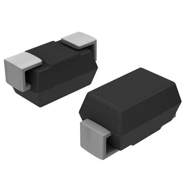
| 供应商器件封装 | DO-214AA (SMBJ) |
| 其它名称 | F2781CT |
| 击穿电压 | 9.5 V |
| 功率-峰值脉冲 | 600W |
| 包装 | 剪切带 (CT) |
| 单向通道 | - |
| 双向通道 | 1 |
| 商标 | Littelfuse |
| 安装类型 | 表面贴装 |
| 安装风格 | SMD/SMT |
| 封装 | Reel |
| 封装/外壳 | DO-214AA,SMB |
| 封装/箱体 | DO-214AA |
| 尺寸 | 3.94 mm W x 4.57 mm L x 2.44 mm H |
| 峰值浪涌电流 | 41 A |
| 峰值脉冲功率耗散 | 600 W |
| 工作温度 | -55°C ~ 150°C (TJ) |
| 工作电压 | 8.55 V |
| 工具箱 | /product-detail/zh/4879287/P6SMB-CA-KIT-ND/2184687 |
| 工厂包装数量 | 3000 |
| 应用 | 通用 |
| 最大工作温度 | + 150 C |
| 最小工作温度 | - 65 C |
| 极性 | Bidirectional |
| 标准包装 | 1 |
| 特色产品 | http://www.digikey.com/product-highlights/ch/zh/littelfuse-tvs-smd-diode-kits/123 |
| 电压-击穿(最小值) | 9.5V |
| 电压-反向关态(典型值) | 8.55V |
| 电压-箝位(最大值)@Ipp | 14.5V |
| 电流-峰值脉冲(10/1000µs) | 42.1A |
| 电源线路保护 | 无 |
| 端接类型 | SMD/SMT |
| 类型 | 齐纳 |
| 系列 | P6SMB |
| 钳位电压 | 14.5 V |


- 商务部:美国ITC正式对集成电路等产品启动337调查
- 曝三星4nm工艺存在良率问题 高通将骁龙8 Gen1或转产台积电
- 太阳诱电将投资9.5亿元在常州建新厂生产MLCC 预计2023年完工
- 英特尔发布欧洲新工厂建设计划 深化IDM 2.0 战略
- 台积电先进制程称霸业界 有大客户加持明年业绩稳了
- 达到5530亿美元!SIA预计今年全球半导体销售额将创下新高
- 英特尔拟将自动驾驶子公司Mobileye上市 估值或超500亿美元
- 三星加码芯片和SET,合并消费电子和移动部门,撤换高东真等 CEO
- 三星电子宣布重大人事变动 还合并消费电子和移动部门
- 海关总署:前11个月进口集成电路产品价值2.52万亿元 增长14.8%


PDF Datasheet 数据手册内容提取
Features Applications n RoHS compliant* and halogen free** n IEC 61000-4-2 ESD (Min. Level 4) n Surface Mount SMB package n IEC 61000-4-4 EFT n Breakdown Voltage: 6.8 to 550 volts n IEC 61000-4-5 Surge n Peak Pulse Power: 600 watts n Typical temperature coefficient: ∆VBR = 0.1 % x VBR @ 25 °C x ∆T P6SMB Transient Voltage Suppressor Diode Series General Information The markets of portable communications, computing and video equipment are challenging the semiconductor industry to develop increasingly smaller electronic components. Bourns offers Transient Voltage Suppressor Diodes for surge and ESD protection applications, in compact chip package DO-214AA (SMB) size format. The Transient Voltage Suppressor series offers a choice of Breakdown Voltages from 6.8 V up to 550 V. Typical fast response times are less than 1.0 picosecond for unidirectional devices and less than 5.0 picoseconds for bidirectional devices from 0 V to Minimum Breakdown Voltage. Bourns® Chip Diodes conform to JEDEC standards, are easy to handle with standard pick and place equipment and the flat configuration minimizes roll away. Maximum Characteristics (@ TA = 25 °C Unless Otherwise Noted) Parameter Symbol Value Unit Peak Pulse Power Dissipation (TP = 1 ms) (Note 1,2) PPK 600 Watts Peak Forward Surge Current 8.3 ms Single Half Sine Wave Superimposed on Rated Load IFSM 100 Amps (JEDEC Method) (Note 3) (MFaoxr iUmnuimdi rIencsttiaonntaal nUenoiutss OFnolryw)ard Voltage @ IPP = 50 A PP66SSMMBB62.280AA ~ ~ P P66SSMMBB250500AA VF 35..50 Volts Operating Temperature Range TJ -55 to +150 °C Storage Temperature Range TSTG -55 to +150 °C 1. Non-repetitive current pulse, per Pulse Waveform graph and derated above TA = 25 °C per Pulse Derating Curve. 2. Thermal Resistance Junction to Lead. 3. 8.3 ms Single Half-Sine Wave duty cycle = 4 pulses maximum per minute (unidirectional units only). How to Order P6SMB 6.8 CA - H Asia-Pacific: Tel: +886-2 2562-4117 Series Email: asiacus@bourns.com P6SMB= SMB/DO-214AA Breakdown Voltage Europe: 6.8 to 550 = 6.8 to 550 VBD (Volts) Tel: +36 88 885 877 Suffix Email: eurocus@bourns.com A = 5 % Tolerance Unidirectional Device The Americas: CA = 5 % Tolerance Bidirectional Device Tel: +1-951 781-5500 Reel Email: americus@bourns.com (blank) = 13 inch reel -H = 7 inch reel www.bourns.com * RoHS Directive 2015/863, Mar 31, 2015 and Annex. **Bourns considers a product to be “halogen free” if (a) the Bromine (Br) content is 900 ppm or less; (b) the Chlorine (Cl) content is 900 ppm or less; and (c) the total Bromine (Br) and Chlorine (Cl) content is 1500 ppm or less. Specifications are subject to change without notice. Users should verify actual device performance in their specific applications. The products described herein and this document are subject to specific legal disclaimers as set forth on the last page of this document, and at www.bourns.com/docs/legal/disclaimer.pdf.
P6SMB Transient Voltage Suppressor Diode Series Electrical Characteristics (@ TA = 25 °C Unless Otherwise Noted) Maximum Maximum Maximum Maximum Working Maximum Clamping Peak Clamping Peak Breakdown Voltage Peak Reverse Unidirectional Device Bidirectional Device Voltage Pulse Voltage Pulse VBR (Volts) RVeovlteargsee @Le VakRaWgMe (10@/10 I0p0p µ s) (1C0/u1r0r0e0n µts) (8@/2 0Ip µps ) C(8u/2r0r eµns)t Part No. Marking Part No. Marking Min. Max. @ IT VRWM IR Vc Ipp Vc Ipp (mA) (V) (μA) (V) (A) (V) (A) P6SMB6.8A 6V8A P6SMB6.8CA 6V8C 6.45 7.14 10 5.8 1000 10.5 58.1 13.7 290.5 P6SMB7.5A 7V5A P6SMB7.5CA 7V5C 7.13 7.88 10 6.4 500 11.3 54 15 270 P6SMB8.2A 8V2A P6SMB8.2CA 8V2C 7.79 8.61 10 7.02 200 12.1 50.4 15.7 252.0 P6SMB9.1A 9V1A P6SMB9.1CA 9V1C 8.65 9.55 1 7.78 50 13.4 45.5 17.4 227.5 P6SMB10A 10A P6SMB10CA 10C 9.5 10.5 1 8.55 10 14.5 42.1 18.9 210.5 P6SMB11A 11A P6SMB11CA 11C 10.5 11.6 1 9.4 5 15.6 39.1 20.3 195.5 P6SMB12A 12A P6SMB12CA 12C 11.4 12.6 1 10.2 5 16.7 36.5 21.7 182.5 P6SMB13A 13A P6SMB13CA 13C 12.4 13.7 1 11.1 1 18.2 33.5 23.7 167.5 P6SMB15A 15A P6SMB15CA 15C 14.3 15.8 1 12.8 1 21.2 28.8 27.6 144.0 P6SMB16A 16A P6SMB16CA 16C 15.2 16.8 1 13.6 1 22.5 27.1 29.3 135.5 P6SMB18A 18A P6SMB18CA 18C 17.1 18.9 1 15.3 1 25.5 24.2 33.2 121.0 P6SMB20A 20A P6SMB20CA 20C 19 21 1 17.1 1 27.7 22 36 110 P6SMB22A 22A P6SMB22CA 22C 20.9 23.1 1 18.8 1 30.6 19.9 39.8 99.5 P6SMB24A 24A P6SMB24CA 24C 22.8 25.2 1 20.5 1 33.2 18.4 43.2 92.0 P6SMB27A 27A P6SMB27CA 27C 25.7 28.4 1 23.1 1 37.5 16.3 48.8 81.5 P6SMB30A 30A P6SMB30CA 30C 28.5 31.5 1 25.6 1 41.4 14.7 53.8 73.5 P6SMB33A 33A P6SMB33CA 33C 31.4 34.7 1 28.2 1 45.7 13.3 59.4 66.5 P6SMB36A 36A P6SMB36CA 36C 34.2 37.8 1 30.8 1 49.9 12.2 64.9 61.0 P6SMB39A 39A P6SMB39CA 39C 37.1 41 1 33.3 1 53.9 11.3 70.1 56.5 P6SMB43A 43A P6SMB43CA 43C 40.9 45.2 1 36.8 1 59.3 10.3 77.1 51.5 P6SMB47A 47A P6SMB47CA 47C 44.7 49.4 1 40.2 1 64.8 9.4 84.2 47.0 P6SMB51A 51A P6SMB51CA 51C 48.5 53.6 1 43.6 1 70.1 8.7 91.1 43.5 P6SMB56A 56A P6SMB56CA 56C 53.2 58.8 1 47.8 1 77 7.9 100.1 39.5 P6SMB62A 62A P6SMB62CA 62C 58.9 65.1 1 53 1 85 7.2 110.5 36.0 P6SMB68A 68A P6SMB68CA 68C 64.6 71.4 1 58.1 1 92 6.6 119.6 33.0 P6SMB75A 75A P6SMB75CA 75C 71.3 78.8 1 64.1 1 103 5.9 133.9 29.5 P6SMB82A 82A P6SMB82CA 82C 77.9 86.1 1 70.1 1 113 5.4 146.9 27.0 P6SMB91A 91A P6SMB91CA 91C 86.5 95.5 1 77.8 1 125 4.9 162.5 24.5 P6SMB100A 100A P6SMB100CA 100C 95 105 1 85.5 1 137 4.5 178.1 22.5 P6SMB110A 110A P6SMB110CA 110C 105 116 1 94 1 152 4 198 20 P6SMB120A 120A P6SMB120CA 120C 114 126 1 102 1 165 3.7 214.5 18.5 P6SMB130A 130A P6SMB130CA 130C 124 137 1 111 1 179 3.4 232.7 17.0 P6SMB150A 150A P6SMB150CA 150C 143 158 1 128 1 207 2.9 269.1 14.5 P6SMB160A 160A P6SMB160CA 160C 152 168 1 136 1 219 2.8 284.7 14.0 P6SMB170A 170A P6SMB170CA 170C 162 179 1 145 1 234 2.6 304.2 13.0 P6SMB180A 180A P6SMB180CA 180C 171 189 1 154 1 246 2.5 319.8 12.5 P6SMB200A 200A P6SMB200CA 200C 190 210 1 171 1 274 2.2 356.2 11.0 P6SMB220A 220A P6SMB220CA 220C 209 231 1 185 1 328 1.9 426.4 9.5 P6SMB250A 250A P6SMB250CA 250C 237 263 1 214 1 344 1.8 447.2 9.0 P6SMB300A 300A P6SMB300CA 300C 285 315 1 256 1 414 1.5 538.2 7.5 P6SMB350A 350A P6SMB350CA 350C 332 368 1 300 1 482 1.3 626.6 6.5 P6SMB400A 400A P6SMB400CA 400C 380 420 1 342 1 548 1.1 712.4 5.5 P6SMB440A 440A P6SMB440CA 440C 418 462 1 376 1 602 1 783 5 P6SMB480A 480A P6SMB480CA 480C 456 504 1 408 1 658 0.9 855.4 4.6 P6SMB510A 510A P6SMB510CA 510C 485 535 1 434 1 698 0.9 907.4 4.3 P6SMB530A 530A P6SMB530CA 530C 503.5 556.5 1 477 1 725 0.8 942.5 4.1 P6SMB540A 540A P6SMB540CA 540C 513 567 1 486 1 740 0.8 962.0 4.1 P6SMB550A 550A P6SMB550CA 550C 522.5 577.5 1 495 1 760 0.8 988.0 3.9 Notes: 1. Suffix ‘A’ denotes a 5 % tolerance unidirectional device. 2. Suffix ‘CA’ denotes a 5 % tolerance bidirectional device. 3. For bidirectional devices with a VR of 10 volts or less, the IR limit is double. Specifications are subject to change without notice. Users should verify actual device performance in their specific applications. The products described herein and this document are subject to specific legal disclaimers as set forth on the last page of this document, and at www.bourns.com/docs/legal/disclaimer.pdf.
3P36S1M2 B- 2Tr manmsi eSnMt VDo Tltraimgem Siunpgp Preostseonrt iDoimodeet eSreries Rating & Characteristic Curves Pulse 1D100e00rat11i0n000g Curve Ma112x200imu11m2200 Non-Repetitive Surge Current Peak Pulse Derating in Percent ofPeak Pulse Derating in Percent ofPeak Pulse Derating in Percent ofPeak Power or CurrentPeak Power or CurrentPeak Pulse Derating in Percent ofPeak Power or Current1Peak Power or Current7527520Peak Pulse Derating in Percent of752Peak Pulse Derating in Percent of505050505050100752Peak Power or Current0Peak Power or Current5050 75275250505050002255 52250550 75755050 1170705050 111010202055 111125255050 111157570505 121270705050 220000 Peak Forward Surge Current (Amps)Peak Forward Surge Current (Amps)Peak Forward Surge Current (Amps)1Peak Forward Surge Current (Amps)111864286420208642000000000000000000011Peak Forward Surge Current (Amps)1Peak Forward Surge Current (Amps)86422010000001186420864200000000000001SS21S2iPiPnniPnuugguSgllllssliePelsneee ueHgH HWSW l2Sl2WsaaeiPaiPellnii nfflddiuH f gudWgSS ttlallShthslesiih5elinen if5 edn88 H eeH8 StWe..W--ha33.ai-WW3nl i Wlfi8dmm fde ma aS.tS-at3hvsvshWiv5si e5ne n me88eae.-.vs31-3W1We 0 m0maavsvsee 11200200 2200 5500 5500110000 110000 0000 2525 50AAm5m0bbi7eien5nAtA t7Tm mT5eebmb1mii0eepnp0ne1tetr 0rTaTa0teeutmumr1rep2ep e(5 e(°r1r°Caa2Ct)t5u)ur1ree5 (0(°1°CC5))0175175200200 0101 2 2 5NNu5ummbbeerNrN o u1oufm0 fmC Cbyb1yece0crlre l eososf f2 a CaC0t tyy6 c62c0l00le eH ssH z azatt 66005 H0Hzz50 100100 AmbAimenbti eTnetm Tpeemrapteurraet u(°rCe )(°C) NumNbuemr boef rC oyfc Cleysc alets 6 a0t H6z0 Hz Pulse Waveform Typical Junction Capacitance 11000000001100000000 TTRR==1100 µ TµTsRsR==1100 µµss 110000 110000TRP=PTe1eaR0ak=k µv1 vsa0aPlP ulµueeesaea (k k(I RIvvRaSaSllMuuMee) ) ((IIRRSSMM)) 1000100000 UUnnididirierecctitoUiUonnnnaiiadld liV irVre e= cc= t0t iio0 oVn nVaall VV == 00 VV I, Peak Pulse Current (%)I, Peak Pulse Current (%)PI, Peak Pulse Current (%)PPI, Peak Pulse Current (%)P150550000I, Peak Pulse Current (%)00I, Peak Pulse Current (%)1PP0500TT5T5AA00A00===TTT22T2PPA55P5=P T°° 2Te°TCCP5CAaAPk ==°T HHeT2Cv2HPaP5aaa5aklll ffu°l H° f vCevv Caav aall(alfluIuul HRHueveea aeSa==(ll=lIMfufR II veRvIR)SRa=a22SSMl2lSuuIMMRMe)ed=d2S=diiwwesesiwMesI11ca caI hhR1ddca Rh00asasdPdPee0a2sSeiePw2ey y S esreruudxdxy ffMrs1seuedcax Mifihl l seeednni s 0s 11asl ePntetd tftfs 1eedeeeoty o i0hti0hfiwreiueesdnwxon0hfidd es s e 0e0en1idww ca l 51e5e he0en ca whs d1 500e0ada asttfdPpd00p0 asei0eiaPeoee0hidp0ds ds y ien y re e duwwds d xrf ub0e db%x %es tftewwsia5aeettb %l hteihn l aa y0aeysh tah1nh kkds p01taiytfh tevk tvf eds oaa0hie( o( o e o Re Rv0h iwnaccde( eo Tb Tn%Rttt d0e ffcaew tT0e t5h ue.uf.wf f a5PyPehp p E0Euk.ofoaII P0dp0a r prEiv odPpI0Pa)i)o( oo.ds .rrrrRrPds e) coAew A .Tr ret mmeSweSb i%iftA b % amtun.efnSti h.aP.ntnpaEyhnMohMIa.kynhrttkM P t)tv o. tr arv( otRaA( o ..cRmeeSTitceT.ftn fu..fn Pu.Mfp EPoIptEorItPr )o.Prr)o..rrA meAS imeSin.nn.MnMttt t .. C Junction Capacitance (pF) C Junction Capacitance (pF) - -JJC Junction Capacitance (pF) -JC Junction Capacitance (pF) -J111001101000011C Junction Capacitance (pF) 001C Junction Capacitance (pF) -J00000 -01J0000100100011Tf 01Tf0=1 0=01 001U=U1 000U=01 00.nn20 .nii205d diM5d iiUM°rr i H°eerCn Tf HeCccTfi z d=cttz=ii ti oo U= ri1U=o1enn .n 2n.nc0aa20i5taid ll5di M l oMi@@ °ir°@ rn HeC HeVCVaczVczRlRt tiR@ioonnVaaRll @@VVRRUnidUirencidtiiorencBatBlii doiVdinr i=eraec l0 ctVi toV io=nBBn a0BBiaidlBd iilV@idd iir@driierreViceerBVcRetccitRidciottoiitinoorinoeannBaBnclaal it ai@dll@di loiVV irVVrnVe eR==a cRc= lt0 0t iVio0 oVV n n=Vaa l0l V VV == 00 VV 00 00 11.0.0 11..00 22.0.0 22..00 33.0.0 33..00 44.0.0 44..00 VTVss ig=ig T=2 =5 5 =5°0 0C 2VmV 5mssV i°igVg p C p -==p- p 5500 mmVVpp--pp 0000 1.01.0 TT,2 ,T .T0imim2e.e0 TT( (,m, m TTsisim)m)ee ((m3m.s0s))3.0 4.04.0 1111 fV =si g111 .fV=0 1=s1 5Mi g10 H. =0mz 5MV0pH m-zpVp-p 1100 1100 BidirBeci1dt1i0ior0e0n0catli o@nVa11lR 0@00V0R 11000000 11000000 1 1 T, TTim, Tei m(mes ()ms) 1 1 VVBB1RR0 - - 1R VR0VeeBvBveRRer rs -s-e ReR B eBervvreeeeararksskdeedo BoBwwr1rnee0na a0V kVk1oddo0lootl0atwwagngne e VV( (VooVl)lt)taaggee ((VV))10010000 VBRV B- RR e-v Reresvee rBsree aBkrdeoakwdno Vwonl tVaoglet a(gVe) (V) Pulse Rating Curve Steady State Power Derating Curve 110000 110000 55.0.0 55..00 100100 TTAA = = 2 255T T° A°ACC == 2255 °°CC W)W) 5.W)0W)5.0 P, Peak Power (KW)P, Peak Power (KW)PP, Peak Power (KW)PPP, Peak Power (KW)P10101110....1001001..00010P, Peak Power (KW)0P, Peak Power (KW)10P..P111...1001 0µµ µ.10ss1011s1.... 001001µ00s..11 µ11µ1s..s00.0 1µµ µ.ss0s µ11s..00 µµs11s1000 µµ 1µssSST0sSThhP µhPoo,11so ,SwwP0 0wPh unn µuonµl ssilwiS sT11SnsnTiPPe1nhPP00en h PNN uu0PP NWo 00u, oP,Wlol0o iTuu1 wss nlPowPuPµsµn niAlel0edµ niNunssulesus-nP-d s0ts-eelrWr= W loTl htsueirWs ees1 i hn 1µPneAneWW lPe2ppeaa0Ws 0Nps- au NP 5eveuvW0Per=WaWa0evlotetee aulo s vuvitie°s Wµnfi2fptvtaiµlenieedColfeoitisd11s-es5evvvo is-ff1t arerrvWt.of.eorteWeeh rmmeh00v.o i°ee mrfr0tWpWeCa orpimma1mm vmfevmreva.oeat me 0tsesvGGi rvisftG ftmeoimer1roiv1frvaarf.or ea.omse0ppGm0rpr hhm rmmhma p s11GsG1h00r0ra amm p1mph0sshs m11s00 mmssRM(AV) Steady State Power Dissipation (RM(AV) Steady State Power Dissipation (W)RM(AV) Steady State Power Dissipation (RM(AV) Steady State Power Dissipation (W)342103421034210.....RM(AV) Steady State Power Dissipation (.....RM(AV) Steady State Power Dissipation (0000000000.....0000000342100.....0000003421034210..........00000000000022255525 225555500660600II05TnIn TnHH 0L6ddHLdzz,0uuI z,u 5nL ccR5R LH77cR0dett760ee6ieti55zauvevi50ssa0Iv dIesecTRn iiTdne7 ssH i tLHdsTLLeL di5ttTLvz,uitiszeo,ou vvi e eoL icvmRaLaceeRs7 m11a7eteLddet 1 tei5pde00oioa 5ivoapvs0ovse0d0rredaeiee0rir1s sd r TLatTL0oatiteoiveo0rutvmauemare11dr ed p0oep0o1 1e0(r1 e0r22(°r2r°C5a5aC51t)tu)u2rr5ee1 1 ((2°112°1C555C55)00)0150115115107707555175112277200550000200220000 Specifications are subject to change without notice. Users should verify actual device performTaPn, cTPePu i,ln sP etuh Wlesieird Wsthpiedcthific applications. TL, TLLe,a dL eTaedm Tpeemrapteurraet u(°reC )(°C) The products described herein and this document are subject to specific legal disclaimers as set forth on the last page of this document, and at www.bourns.com/docs/legal/disclaimer.pdf.
P6S3M31B2 T r-a 2n smiemnt SVMoltDa gTeri mSumppinrges Psootre Dnitoidoem Seeterires Product Dimensions Recommended Footprint CATHODE A A a A BAND (FOR UNIDIRECTIONAL PRODUCTS ONLY) B C B b B c C F D Dimension SMB (DO-214AA) 2.69 a (Max.) G E (0.106) C D 2.10 b (Min.) (0.083) 1.27 c (Min.) DIMENSIONS: MM F (0.050) Dimension SMB (D(OINC-H2E1S)4AA) 4.06 - 4.57 MM A DIMENSIONS: (0.160 - 0.180) (INCHES) B E 3.30 - 3.94 (0.130 - 0.155) 1.95 - 2.20 Physical Specifications C (0.077 - 0.0M8M7) DIMENSIONS: Case ...........................................Molded plastic per UL Class 94V-0 5.21 - 5(I.N5C9H ES) D Polarity.......................Cathode band indicates unidirectional device (0.205 - 0.220) No cathode band indicates bidirectional device 0.05 - 0.203 E (0.002 - 0.008) 2.13 - 2.44 F Environmental Specifications (0.084 - 0.096) 0.76 - 1.52 Moisture Sensitivity Level ................................................................1 G (0.030 - 0.060) ESD Classification (HBM).............................................................3B MM DIMENSIONS: (INCHES) Specifications are subject to change without notice. Users should verify actual device performance in their specific applications. The products described herein and this document are subject to specific legal disclaimers as set forth on the last page of this document, and at www.bourns.com/docs/legal/disclaimer.pdf.
CPD6SDMFNB5 T-r0a5n0s4ieNn -t TVVoSlt/aSgtee eSruinpgp rDeisosdoer ADriroadye Series Packaging Information The product will be dispensed in tape and reel format (see diagram below). P 0 P1 E T d Index Hole 120 ° F D2 W B D1 D P A C Unidirectional Trailer Product Device Leader Orientation ....... ....... ....... ....... W1 End ....... ....... ....... ....... Start MM DIMENSIONS: (INCHES) 10 pitches (min.) 10 pitches (min.) Devices are packed in accordance with EIA standard RS-481-A and specifications shown here. Direction of Feed SMB (DO-214AA) Item Symbol 7 Inch Reel 13 Inch Reel 3.67 ± 0.20 Carrier Width A (0.144 ± 0.008) 5.60 ± 0.20 Carrier Length B (0.220 ± 0.008) 2.57 ± 0.20 Carrier Depth C (0.101 ± 0.008) 1.50 ± 0.10 Sprocket Hole d (0.059 ± 0.004) 178 330 Reel Outside Diameter D (7.008) (12.992) 50.0 Reel Inner Diameter D1 (1.969) MIN. 13.0 ± 0.20 Feed Hole Diameter D2 (0.512 ± 0.008) 1.75 ± 0.10 Sprocket Hole Position E (0.069 ± 0.004) 5.50 ± 0.05 Punch Hole Position F (0.217 ± 0.002) 8.00 ± 0.10 Punch Hole Pitch P (0.315 ± 0.004) 4.00 ± 0.10 Sprocket Hole Pitch P0 (0.157 ± 0.004) 2.00 ± 0.05 Embossment Center P1 (0.079 ± 0.002) 0.30 ± 0.10 Overall Tape Thickness T (0.012 ± 0.004) 12.00 ± 0.30 Tape Width W (0.472 ± 0.012) 18.4 Reel Width W1 (0.724) MAX. Quantity per Reel -- 500 3,000 REV. 03/20 Specifications are subject to change without notice. Users should verify actual device performance in their specific applications. The products described herein and this document are subject to specific legal disclaimers as set forth on the last page of this document, and at www.bourns.com/docs/legal/disclaimer.pdf.
Legal Disclaimer Notice This legal disclaimer applies to purchasers and users of Bourns® products manufactured by or on behalf of Bourns, Inc. and its affiliates (collectively, “Bourns”). Unless otherwise expressly indicated in writing, Bourns® products and data sheets relating thereto are subject to change without notice. Users should check for and obtain the latest relevant information and verify that such information is current and complete before placing orders for Bourns® products. The characteristics and parameters of a Bourns® product set forth in its data sheet are based on laboratory conditions, and statements regarding the suitability of products for certain types of applications are based on Bourns’ knowledge of typical requirements in generic applications. The characteristics and parameters of a Bourns® product in a user application may vary from the data sheet characteristics and parameters due to (i) the combination of the Bourns® product with other components in the user’s application, or (ii) the environment of the user application itself. The characteristics and parameters of a Bourns® product also can and do vary in different applications and actual performance may vary over time. Users should always verify the actual performance of the Bourns® product in their specific devices and applications, and make their own independent judgments regarding the amount of additional test margin to design into their device or application to compensate for differences between laboratory and real world conditions. Unless Bourns has explicitly designated an individual Bourns® product as meeting the requirements of a particular industry standard (e.g., ISO/TS 16949) or a particular qualification (e.g., UL listed or recognized), Bourns is not responsible for any failure of an individual Bourns® product to meet the requirements of such industry standard or particular qualification. Users of Bourns® products are responsible for ensuring compliance with safety-related requirements and standards applicable to their devices or applications. Bourns® products are not recommended, authorized or intended for use in nuclear, lifesaving, life-critical or life-sustaining ap- plications, nor in any other applications where failure or malfunction may result in personal injury, death, or severe property or environmental damage. Unless expressly and specifically approved in writing by two authorized Bourns representatives on a case-by-case basis, use of any Bourns® products in such unauthorized applications might not be safe and thus is at the user’s sole risk. Life-critical applications include devices identified by the U.S. Food and Drug Administration as Class III devices and generally equivalent classifications outside of the United States. Bourns expressly identifies those Bourns® standard products that are suitable for use in automotive applications on such products’ data sheets in the section entitled “Applications.” Unless expressly and specifically approved in writing by two authorized Bourns representatives on a case-by-case basis, use of any other Bourns® standard products in an automotive application might not be safe and thus is not recommended, authorized or intended and is at the user’s sole risk. If Bourns expressly identifies a sub-category of automotive application in the data sheet for its standard products (such as infotainment or lighting), such identification means that Bourns has reviewed its standard product and has determined that if such Bourns® standard product is considered for potential use in automotive applications, it should only be used in such sub-category of automotive applications. Any reference to Bourns® standard product in the data sheet as compliant with the AEC-Q standard or “automotive grade” does not by itself mean that Bourns has approved such product for use in an automotive application. Bourns® standard products are not tested to comply with United States Federal Aviation Administration standards generally or any other generally equivalent governmental organization standard applicable to products designed or manufactured for use in aircraft or space applications. Bourns expressly identifies Bourns® standard products that are suitable for use in aircraft or space applications on such products’ data sheets in the section entitled “Applications.” Unless expressly and specifically approved in writing by two authorized Bourns representatives on a case-by-case basis, use of any other Bourns® standard product in an aircraft or space application might not be safe and thus is not recommended, authorized or intended and is at the user’s sole risk. The use and level of testing applicable to Bourns® custom products shall be negotiated on a case-by-case basis by Bourns and the user for which such Bourns® custom products are specially designed. Absent a written agreement between Bourns and the user regarding the use and level of such testing, the above provisions applicable to Bourns® standard products shall also apply to such Bourns® custom products. Users shall not sell, transfer, export or re-export any Bourns® products or technology for use in activities which involve the design, development, production, use or stockpiling of nuclear, chemical or biological weapons or missiles, nor shall they use Bourns® products or technology in any facility which engages in activities relating to such devices. The foregoing restrictions apply to all uses and applications that violate national or international prohibitions, including embargos or international regulations. Further, Bourns® products and Bourns technology and technical data may not under any circumstance be exported or re-exported to countries subject to international sanctions or embargoes. Bourns® products may not, without prior authorization from Bourns and/or the U.S. Government, be resold, transferred, or re-exported to any party not eligible to receive U.S. commodities, software, and technical data. To the maximum extent permitted by applicable law, Bourns disclaims (i) any and all liability for special, punitive, consequential, incidental or indirect damages or lost revenues or lost profits, and (ii) any and all implied warranties, including implied warranties of fitness for particular purpose, non-infringement and merchantability. For your convenience, copies of this Legal Disclaimer Notice with German, Spanish, Japanese, Traditional Chinese and Simplified Chinese bilingual versions are available at: Web Page: http://www.bourns.com/legal/disclaimers-terms-and-policies PDF: http://www.bourns.com/docs/Legal/disclaimer.pdf C1753 05/17/18R