 Datasheet下载
- 型号: P6KE550A
- 制造商: Littelfuse
- 库位|库存: xxxx|xxxx
- 要求:
| 数量阶梯 | 香港交货 | 国内含税 |
| +xxxx | $xxxx | ¥xxxx |
查看当月历史价格
查看今年历史价格
P6KE550A产品简介:
ICGOO电子元器件商城为您提供P6KE550A由Littelfuse设计生产,在icgoo商城现货销售,并且可以通过原厂、代理商等渠道进行代购。 P6KE550A价格参考。LittelfuseP6KE550A封装/规格:TVS - 二极管, 。您可以下载P6KE550A参考资料、Datasheet数据手册功能说明书,资料中有P6KE550A 详细功能的应用电路图电压和使用方法及教程。
Littelfuse Inc.的P6KE550A是一款瞬态电压抑制(TVS)二极管,广泛应用于各种电子设备中,以保护电路免受瞬态过电压事件的影响。这类器件在通信、消费电子、工业控制等领域有广泛应用。

应用场景:

1. 通信设备:
   - P6KE550A可以用于保护通信接口,如RS-232、RS-485、USB等,防止雷击、静电放电(ESD)和电源波动对敏感电路造成损害。
   - 在无线通信模块中,它可以保护天线和射频前端电路,确保信号传输的稳定性和可靠性。

2. 消费电子产品:
   - 在智能手机、平板电脑、笔记本电脑等便携式设备中,P6KE550A可用于保护充电接口、耳机插孔和其他外部连接器,避免因不当操作或外界干扰导致的损坏。
   - 它还可以用于保护内部电路,如摄像头模块、显示屏驱动电路等,提高产品的整体可靠性。

3. 工业控制系统:
   - 在工业自动化设备中,P6KE550A可用于保护传感器、执行器、PLC(可编程逻辑控制器)等关键组件,确保这些设备在恶劣环境下正常工作。
   - 它也可以用于保护电机驱动器、电源模块等,防止电力波动或短路对系统造成影响。

4. 汽车电子:
   - 在汽车电子系统中,P6KE550A可用于保护车载娱乐系统、导航系统、车身控制系统等,确保这些系统的稳定运行。
   - 它还可以用于保护电池管理系统(BMS),防止电池充放电过程中可能出现的电压异常情况。

5. 家用电器:
   - 在家用电器如洗衣机、空调、冰箱等中,P6KE550A可用于保护控制板上的微处理器、传感器等关键部件,延长设备的使用寿命。

总之,P6KE550A作为一种高性能的TVS二极管,能够有效抑制瞬态过电压,保护各种电子设备中的敏感电路,确保其在不同环境下的可靠性和稳定性。
| 参数 | 数值 |
| 产品目录 | |
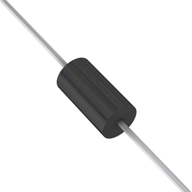
| 描述 | TVS DIODE 495VWM 760VC AXIALTVS 二极管 - 瞬态电压抑制器 P6KE550A |
| 产品分类 | |
| 品牌 | Littelfuse Inc |
| 产品手册 | |
| 产品图片 |
|
| rohs | 符合RoHS不受无铅要求限制 / 符合限制有害物质指令(RoHS)规范要求 |
| 产品系列 | 二极管与整流器,TVS二极管,TVS 二极管 - 瞬态电压抑制器,Littelfuse P6KE550AP6KE |
| 数据手册 | |
| 产品型号 | P6KE550A |
| 不同频率时的电容 | - |
| 产品培训模块 | http://www.digikey.cn/PTM/IndividualPTM.page?site=cn&lang=zhs&ptm=22970 |
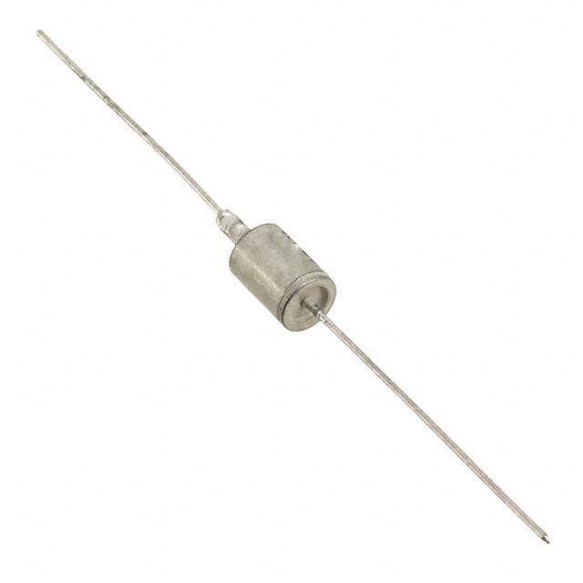
| 产品目录绘图 |
|
| 产品种类 | TVS 二极管 - 瞬态电压抑制器 |
| 供应商器件封装 | DO-204AC(DO-15) |
| 其它名称 | F5657TR |
| 击穿电压 | 522.5 V |
| 功率-峰值脉冲 | 600W |
| 包装 | 带卷 (TR) |
| 单位重量 | 400 mg |
| 单向通道 | 1 |
| 双向通道 | - |
| 商标 | Littelfuse |
| 安装类型 | 通孔 |
| 安装风格 | Through Hole |
| 封装 | Reel |
| 封装/外壳 | DO-204AC,DO-15,轴向 |
| 封装/箱体 | DO-204AC |
| 尺寸 | 3.6 mm Dia. x 3.6 (Max) mm W x 7.6 mm L |
| 峰值浪涌电流 | 800 mA |
| 峰值脉冲功率耗散 | 600 W |
| 工作温度 | -55°C ~ 150°C (TJ) |
| 工作电压 | 495 V |
| 工厂包装数量 | 4000 |
| 应用 | 通用 |
| 最大工作温度 | + 175 C |
| 最小工作温度 | - 55 C |
| 极性 | Unidirectional |
| 标准包装 | 4,000 |
| 电压-击穿(最小值) | 522.5V |
| 电压-反向关态(典型值) | 495V |
| 电压-箝位(最大值)@Ipp | 760V |
| 电流-峰值脉冲(10/1000µs) | 800mA |
| 电源线路保护 | 无 |
| 端接类型 | Axial |
| 类型 | 齐纳 |
| 系列 | P6KE |
| 钳位电压 | 760 V |


- 商务部:美国ITC正式对集成电路等产品启动337调查
- 曝三星4nm工艺存在良率问题 高通将骁龙8 Gen1或转产台积电
- 太阳诱电将投资9.5亿元在常州建新厂生产MLCC 预计2023年完工
- 英特尔发布欧洲新工厂建设计划 深化IDM 2.0 战略
- 台积电先进制程称霸业界 有大客户加持明年业绩稳了
- 达到5530亿美元!SIA预计今年全球半导体销售额将创下新高
- 英特尔拟将自动驾驶子公司Mobileye上市 估值或超500亿美元
- 三星加码芯片和SET,合并消费电子和移动部门,撤换高东真等 CEO
- 三星电子宣布重大人事变动 还合并消费电子和移动部门
- 海关总署:前11个月进口集成电路产品价值2.52万亿元 增长14.8%


PDF Datasheet 数据手册内容提取
Transient Voltage Suppression Diodes Axial Leaded – 600W > P6KE series P6KE Series RoHS Pb e3 Description Bi-directional The P6KE Series is designed specifically to protect sensitive electronic equipment from voltage transients induced by lightning and other transient voltage events. Features Uni-directional • 600W peak pulse • Compatible with high capability at 10/1000μs temperature reflow waveform, repetition rate soldering (260°C/40 s) (duty cycles):0.01% • V @ T= V @25°C BR J BR • Glass passivated chip x (1+αT x (T - 25)) Agency Approvals J junction in DO-15 Package (αT:Temperature • Fast response time: Coefficient, typical value AGENCY AGENCY FILE NUMBER typically less than 1.0ps is 0.1%) E230531 from 0 Volts to BV min • IL Recognized epoxy • Excellent clamping meeting flammability Maximum Ratings and Thermal Characteristics capability classification V-0 (T =25OC unless otherwise noted) • Typical failure mode is • Matte tin lead–free plated A short from over-specified • Halogen free and RoHS Parameter Symbol Value Unit voltage or current compliant Peak Pulse Power Dissipation by • Whisker test conducted • Pb-free E3 means 2nd 10/1000μs Test Waveform (Fig.2) P 600 W based on Table 4a and 4c level interconnect is PPM (Note 1), (Note 4) of JEDEC JESD201A Pb-free and the terminal Steady State Power Dissipation on P 5.0 W • IEC-61000-4-2 ESD finish material is tin(Sn) Infinite Heat Sink at TL=75ºC D 30kV(Air), 30kV (Contact) (IPC/JEDEC J-STD- Peak Forward Surge Current, 8.3ms 609A.01) • EFT protection of data Single Half Sine Wave Unidirectional I 100 A Only (Note 2) FSM lines in accordance with Maximum Instantaneous Forward IEC 61000-4-4 Voltage at 50A for Unidirectional V 3.5/5.0 V F • Low incremental surge Only (Note 3) resistance Operating Junction and Storage Temperature Range TJ, TSTG -55 to 175 °C • Typical IR less than 1μA when V min>12V Typical Thermal Resistance BR R 20 °C/W Junction to Lead θJL Applications Typical Thermal Resistance R 75 °C/W Junction to Ambient θJA TVS components are ideal for the protection of I/O Notes: interfaces, V bus and other vulnerable circuits used in 1. Non-repetitive current pulse , per Fig. 4 and derated above T (initial) = 25OC per Fig. 3. CC J telecom, computer, industrial and consumer electronic 2. Measured on 8.3ms single half sine wave or equivalent square wave, duty cycle=4 per applications. minute maximum. 3. V < 3.5V for single die parts and V< 5.0V for stacked-die parts. F F 4. The P of stacked-die parts is 800W and please contact littelfuse for the detail PPM stacked-die parts. Functional Diagram Additional Infomarion Bi-directional Datasheet Resources Samples Cathode Anode Uni-directional © 2017 Littelfuse, Inc. Specifications are subject to change without notice. Revised: 05/22/17
Transient Voltage Suppression Diodes Axial Leaded – 600W > P6KE series Electrical Characteristics (T=25°C unless otherwise noted) A Reverse Breakdown Test Maximum Maximum Maximum Agency NuPmarbt e r NuPmarbt e r VSotlatangde o Vff V(Vooltlatsg)e @ V BIR CurIre nt CVlaomltapgineg PulseP eCaukr rent LReeavkeargsee Approval (Uni) (Bi) R T T I @ V (Volts) (mA) V @ I (V) I (A) R R MIN MAX C pp pp (µA) P6KE6.8A P6KE6.8CA 5.80 6.45 7.14 10 10.5 58.1 1000 X P6KE7.5A P6KE7.5CA 6.40 7.13 7.88 10 11.3 54.0 500 X P6KE8.2A P6KE8.2CA 7.02 7.79 8.61 10 12.1 50.4 200 X P6KE9.1A P6KE9.1CA 7.78 8.65 9.55 1 13.4 45.5 50 X P6KE10A P6KE10CA 8.55 9.50 10.50 1 14.5 42.1 10 X P6KE11A P6KE11CA 9.40 10.50 11.60 1 15.6 39.1 5 X P6KE12A P6KE12CA 10.20 11.40 12.60 1 16.7 36.5 5 X P6KE13A P6KE13CA 11.10 12.40 13.70 1 18.2 33.5 1 X P6KE15A P6KE15CA 12.80 14.30 15.80 1 21.2 28.8 1 X P6KE16A P6KE16CA 13.60 15.20 16.80 1 22.5 27.1 1 X P6KE18A P6KE18CA 15.30 17.10 18.90 1 25.2 24.2 1 X P6KE20A P6KE20CA 17.10 19.00 21.00 1 27.7 22.0 1 X P6KE22A P6KE22CA 18.80 20.90 23.10 1 30.6 19.9 1 X P6KE24A P6KE24CA 20.50 22.80 25.20 1 33.2 18.4 1 X P6KE27A P6KE27CA 23.10 25.70 28.40 1 37.5 16.3 1 X P6KE30A P6KE30CA 25.60 28.50 31.50 1 41.4 14.7 1 X P6KE33A P6KE33CA 28.20 31.40 34.70 1 45.7 13.3 1 X P6KE36A P6KE36CA 30.80 34.20 37.80 1 49.9 12.2 1 X P6KE39A P6KE39CA 33.30 37.10 41.00 1 53.9 11.3 1 X P6KE43A P6KE43CA 36.80 40.90 45.20 1 59.3 10.3 1 X P6KE47A P6KE47CA 40.20 44.70 49.40 1 64.8 9.4 1 X P6KE51A P6KE51CA 43.60 48.50 53.60 1 70.1 8.7 1 X P6KE56A P6KE56CA 47.80 53.20 58.80 1 77.0 7.9 1 X P6KE62A P6KE62CA 53.00 58.90 65.10 1 85.0 7.2 1 X P6KE68A P6KE68CA 58.10 64.60 71.40 1 92.0 6.6 1 X P6KE75A P6KE75CA 64.10 71.30 78.80 1 103.0 5.9 1 X P6KE82A P6KE82CA 70.10 77.90 86.10 1 113.0 5.4 1 X P6KE91A P6KE91CA 77.80 86.50 95.50 1 125.0 4.9 1 X P6KE100A P6KE100CA 85.50 95.00 105.00 1 137.0 4.5 1 X P6KE110A P6KE110CA 94.00 105.00 116.00 1 152.0 4.0 1 X P6KE120A P6KE120CA 102.00 114.00 126.00 1 165.0 3.7 1 X P6KE130A P6KE130CA 111.00 124.00 137.00 1 179.0 3.4 1 X P6KE150A P6KE150CA 128.00 143.00 158.00 1 207.0 2.9 1 X P6KE160A P6KE160CA 136.00 152.00 168.00 1 219.0 2.8 1 X P6KE170A P6KE170CA 145.00 162.00 179.00 1 234.0 2.6 1 X P6KE180A P6KE180CA 154.00 171.00 189.00 1 246.0 2.5 1 X P6KE200A P6KE200CA 171.00 190.00 210.00 1 274.0 2.2 1 X P6KE220A P6KE220CA 185.00 209.00 231.00 1 328.0 1.9 1 X P6KE250A P6KE250CA 214.00 237.00 263.00 1 344.0 1.8 1 X P6KE300A P6KE300CA 256.00 285.00 315.00 1 414.0 1.5 1 X P6KE350A P6KE350CA 300.00 332.00 368.00 1 482.0 1.3 1 P6KE400A P6KE400CA 342.00 380.00 420.00 1 548.0 1.1 1 P6KE440A P6KE440CA 376.00 418.00 462.00 1 602.0 1.0 1 P6KE480A P6KE480CA 408.00 456.00 504.00 1 658.0 0.9 1 P6KE510A P6KE510CA 434.00 485.00 535.00 1 698.0 0.9 1 P6KE530A P6KE530CA 451.00 503.50 556.50 1 725.0 0.8 1 P6KE540A P6KE540CA 460.00 513.00 567.00 1 740.0 0.8 1 P6KE550A P6KE550CA 468.00 522.50 577.50 1 760.0 0.8 1 P6KE600A P6KE600CA 512.00 570.00 630.00 1 828.0 0.75 1 For bidirectional type having V of 10 volts and less, the I limit is double. R R For parts without A , the V is ± 10% and V is 5% higher than with A parts BR C © 2017 Littelfuse, Inc. Specifications are subject to change without notice. Revised: 05/22/17
Transient Voltage Suppression Diodes Axial Leaded – 600W > P6KE series I-V Curve Characteristics Uni-directional Bi-directional Ipp IT Vc VBRVR V Vc VBRVR IR V IRVF IR VRVBRVc IT IT Ipp Ipp P Peak Pulse Power Dissipation -- Max power dissipation PPM V Stand-off Voltage -- Maximum voltage that can be applied to the TVS without operation R V Breakdown Voltage -- Maximum voltage that flows though the TVS at a specified test current (I) BR T V Clamping Voltage -- Peak voltage measured across the TVS at a specified Ippm (peak impulse current) C I Reverse Leakage Current -- Current measured at V R R V Forward Voltage Drop for Uni-directional F Ratings and Characteristic Curves (T=25°C unless otherwise noted) A Figure 1 - TVS Transients Clamping Waveform Figure 2 - Peak Pulse Power Rating Voltage Transients 100 W) TJ initial = Tamb k Voltage Across TVS er ( 10 stacked-die, 800W w at 10/1000µs, 25°C nt o oltage or Curre Current Through TVS ak Pulse P 1 Sati n1g0l/e1 0d0ie0,µ6s0,0 2W5° C V e P -M P P P 0.1 0.001 0.01 0.1 1 10 t-Pulse Width (ms) Time d continues on next page. © 2017 Littelfuse, Inc. Specifications are subject to change without notice. Revised: 05/22/17
Transient Voltage Suppression Diodes Axial Leaded – 600W > P6KE series Ratings and Characteristic Curves (T=25°C unless otherwise noted) (Continued) A Figure 3 - Peak Pulse Power Derating Curve Figure 4 - Pulse Waveform 150 k Pulse Power (P) or Current (I)PPPPDerating in Percentage %125705050 I- Peak Pulse Current, % IPPMRSM 15000 tr=1PI0PeµPasMke cVaHIlPuaPelMf Va(lI Pu P1a2eTPac0sM usuJ / rd1=)ltrsh02eeee50nfi W °0tpnC dµioedeisdtnceh tabc( wyt.yds hW ) R teiosar. E ev5d .0eteAh%ffieon orpemfde IaPkP M a Pe 0 td 0 25 50 75 100 125 150 175 200 0 0 1.0 2.0 3.0 4.0 T - Initial Junction Temperature (ºC) J t-Time (ms) Figure 5 - Typical Junction Capacitance Figure 6 - Typical Transient Thermal Impedance 100000 100 W) 10000 Uni-direc(cid:23)onal V=0V °e (C/ Bi-direc(cid:23)onal V=0V anc pF) 1000 mped 10 Cj ( mal I er h 100 Uni-direc(cid:23)onal ent T 1 Bi-direc(cid:23)onal nsi 10 V=VR Tra 1 0.1 1 10 100 1000 0.01 0.1 1 10 100 1000 V - Reverse Breakdown Voltage (V) TP-Pulse Duration (s) BR Figure 7 - Maximum Non-Repetitive Peak Forward Figure 8 - Peak Forward Voltage Drop vs Peak Forward Surge Current Uni-Directional Only Current (Typical Values) 120 100.0 Single die A) nt(100 e urve Curr 80 urrent(A) 10.0 Stacked-die S C ard 60 ard w w M -Peak For 2400 -IPeak ForF 1.0 S F I 0 1 10 100 0.1 Number of Cycles at 60 Hz 0.0 1.0 2.0 3.0 4.0 5.0 6.0 7.0 8.0 9.0 VF-Peak Forward Voltage(V) © 2017 Littelfuse, Inc. Specifications are subject to change without notice. Revised: 05/22/17
Transient Voltage Suppression Diodes Axial Leaded – 600W > P6KE series Soldering Parameters Lead–free Reflow Condition assembly TP tp - Temperature Min (T ) 150°C Ramp-up Critical Zone Pre Heat - Temperature Max (Tss(m(mina)x)) 200°C T) TL tL TL to TP - Time (min to max) (ts) 60 – 180 secs (ure Ts(max) Atov epreaagke ramp up rate (Liquidus Temp (TA) 3°C/second max TemperatTs(min) Prethseat Ramp-down T to T - Ramp-up Rate 3°C/second max S(max) A Reflow - Temperature (TA) (Liquidus) 217°C 25˚C t 25˚C to Peak Time (t) - Time (min to max) (t) 60 – 150 seconds s Peak Temperature (T) 260+0/-5 °C P Time within 5°C of actual peak Flow/Wave Soldering (Solder Dipping) 20 – 40 seconds Temperature (t) p Ramp-down Rate 6°C/second max Peak Temperature : 265OC Time 25°C to peak Temperature (T) 8 minutes Max. Dipping Time : 10 seconds P Do not exceed 260°C Soldering : 1 time Physical Specificationst C Environmental Specifications Weight 0.015oz., 0.4g High Temp. Storage JESD22-A103 JEDEC DO-204AC (DO-15) molded Case plastic body over passivated junction. HTRB JESD22-A108 Color band denotes the cathode except Polarity Temperature Cycling JESD22-A104 Bipolar. Matte Tin axial leads, solderable per H3TRB JESD22-A101 Terminal JESD22-B102. RSH JESD22-B106 Dimensions Cathode Band D (for uni-directional products only) Inches Millimeters Dimensions Min Max Min Max C A 1.000 - 25.40 - A B A B 0.230 0.300 5.80 7.60 C 0.028 0.034 0.71 0.86 DO-204AC (DO-15) D 0.104 0.140 2.60 3.60 © 2017 Littelfuse, Inc. Specifications are subject to change without notice. Revised: 05/22/17
Transient Voltage Suppression Diodes Axial Leaded – 600W > P6KE series Part Numbering System Part Marking System P6KExxxXXX Cathode Band OPTION CODE: (for uni-directional BLANK Reel Tape products only) F -B Bulk Packaging YYWW TYPE CODE: Littelfuse Logo Trace Code Marking A Uni-Directional (5% V Voltage Tolerance) YY:Year Code CA Bi-Directional (5% V B VRoltage Tolerance) WW: Week Code BR P6KEXXX VBR VOLTAGE CODE Product Type (Refer to the Electrical Characteristics table) SERIES CODE Packaging Component Packaging Part Number Quantity Packaging Specification Package Option P6KExxxXX DO-204AC 4000 Tape & Reel EIA STD RS-296 P6KExxxXX-B DO-204AC 1000 BULK Littelfuse Spec. Tape and Reel Specification Off Center (625.5.06) either side 2.0(5633.+00+.20.709//--10..00)39 0.028(0.7) 0.047 0.236 (1.2) (6.0) 0.197+/-0.020 (5.0+/- 0.5) Dimensions are in 13.0 inches/mm (330.2) 3.0 (76.2) 0.68 (17.27) 2.75 (69.85) Direction of Feed Recess Depth Max. 0.75 (19.05) © 2017 Littelfuse, Inc. Specifications are subject to change without notice. Revised: 05/22/17