 Datasheet下载
- 型号: P4SMA75CA
- 制造商: Littelfuse
- 库位|库存: xxxx|xxxx
- 要求:
| 数量阶梯 | 香港交货 | 国内含税 |
| +xxxx | $xxxx | ¥xxxx |
查看当月历史价格
查看今年历史价格
P4SMA75CA产品简介:
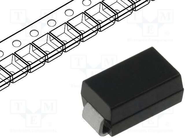
ICGOO电子元器件商城为您提供P4SMA75CA由Littelfuse设计生产,在icgoo商城现货销售,并且可以通过原厂、代理商等渠道进行代购。 P4SMA75CA价格参考¥0.56-¥0.77。LittelfuseP4SMA75CA封装/规格:TVS - 二极管, 103V Clamp 4A Ipp Tvs Diode Surface Mount DO-214AC (SMA)。您可以下载P4SMA75CA参考资料、Datasheet数据手册功能说明书,资料中有P4SMA75CA 详细功能的应用电路图电压和使用方法及教程。
Bourns Inc. 的 P4SMA75CA 是一款瞬态电压抑制二极管(TVS),属于P4SMA系列,采用SMA封装,双向击穿电压为75V。该器件主要用于保护敏感电子元件免受瞬态高压脉冲的损害,如静电放电(ESD)、雷击感应、电感负载切换等引起的浪涌电压。

典型应用场景包括:

1. 电源电路保护:适用于直流电源输入端口,防止因电源波动或反接导致的过压损坏。
2. 通信接口防护:广泛用于RS-485、CAN总线、以太网等工业通信接口,提升系统抗干扰能力。
3. 消费类电子产品:应用于电视、机顶盒、智能家居设备中,保护内部电路免受ESD冲击。
4. 工业控制设备:在PLC、传感器、继电器驱动电路中提供可靠的过压保护。
5. 汽车电子系统:用于车载电子模块(如照明控制、ECU接口)中,应对负载突降(Load Dump)等瞬态事件。

P4SMA75CA具有响应速度快、钳位性能优异、可靠性高等特点,符合RoHS和无卤要求,适合自动化贴装,广泛应用于需要高稳定性和紧凑设计的中低功率电子系统中。
| 参数 | 数值 |
| 产品目录 | |
| 描述 | TVS DIODE 64.1VWM 103VC SMDTVS 二极管 - 瞬态电压抑制器 64.1Vso 71.3Vbr |
| 产品分类 | |
| 品牌 | Littelfuse |
| 产品手册 | |
| 产品图片 |
|
| rohs | 符合RoHS不受无铅要求限制 / 符合限制有害物质指令(RoHS)规范要求 |
| 产品系列 | 二极管与整流器,TVS二极管,TVS 二极管 - 瞬态电压抑制器,Littelfuse P4SMA75CAP4SMA |
| 数据手册 | |
| 产品型号 | P4SMA75CA |
| 不同频率时的电容 | - |
| 产品培训模块 | http://www.digikey.cn/PTM/IndividualPTM.page?site=cn&lang=zhs&ptm=22970 |
| 产品种类 | TVS 二极管 - 瞬态电压抑制器 |
| 供应商器件封装 | DO-214AC(SMA) |
| 其它名称 | P4SMA75CADKR |
| 击穿电压 | 71.3 V |
| 功率-峰值脉冲 | 400W |
| 包装 | Digi-Reel® |
| 单向通道 | - |
| 双向通道 | 1 |
| 商标 | Littelfuse |
| 安装类型 | 表面贴装 |
| 安装风格 | SMD/SMT |
| 封装 | Reel |
| 封装/外壳 | DO-214AC,SMA |
| 封装/箱体 | DO-214AC |
| 尺寸 | 2.79 mm W x 4.5 mm L x 2.29 mm H |
| 峰值浪涌电流 | 4 A |
| 峰值脉冲功率耗散 | 400 W |
| 工作温度 | -55°C ~ 150°C (TJ) |
| 工作电压 | 64.1 V |
| 工厂包装数量 | 5000 |
| 应用 | 通用 |
| 最大工作温度 | + 150 C |
| 最小工作温度 | - 65 C |
| 极性 | Bidirectional |
| 标准包装 | 1 |
| 电压-击穿(最小值) | 71.3V |
| 电压-反向关态(典型值) | 64.1V |
| 电压-箝位(最大值)@Ipp | 103V |
| 电流-峰值脉冲(10/1000µs) | 4A |
| 电源线路保护 | 无 |
| 端接类型 | SMD/SMT |
| 类型 | 齐纳 |
| 系列 | P4SMA |
| 钳位电压 | 103 V |


- 商务部:美国ITC正式对集成电路等产品启动337调查
- 曝三星4nm工艺存在良率问题 高通将骁龙8 Gen1或转产台积电
- 太阳诱电将投资9.5亿元在常州建新厂生产MLCC 预计2023年完工
- 英特尔发布欧洲新工厂建设计划 深化IDM 2.0 战略
- 台积电先进制程称霸业界 有大客户加持明年业绩稳了
- 达到5530亿美元!SIA预计今年全球半导体销售额将创下新高
- 英特尔拟将自动驾驶子公司Mobileye上市 估值或超500亿美元
- 三星加码芯片和SET,合并消费电子和移动部门,撤换高东真等 CEO
- 三星电子宣布重大人事变动 还合并消费电子和移动部门
- 海关总署:前11个月进口集成电路产品价值2.52万亿元 增长14.8%


PDF Datasheet 数据手册内容提取
Features Applications n RoHS compliant* and halogen free** n IEC 61000-4-2 ESD (Min. Level 4) n Surface Mount SMA package n IEC 61000-4-4 EFT n Breakdown Voltage: 6.8 to 550 volts n IEC 61000-4-5 Surge n Peak Pulse Power: 400 watts n Typical temperature coefficient: ∆VBR = 0.1 % x VBR @ 25 °C x ∆T P4SMA Transient Voltage Suppressor Diode Series General Information The markets of portable communications, computing and video equipment are challenging the semiconductor industry to develop increasingly smaller electronic components. Bourns offers Transient Voltage Suppressor Diodes for surge and ESD protection applications, in compact chip package DO-214AC (SMA) size format. The Transient Voltage Suppressor series offers a choice of Breakdown Voltages from 6.8 V up to 550 V. Typical fast response times are less than 1.0 picosecond for unidirectional devices and less than 5.0 picoseconds for bidirectional devices. Bourns® Chip Diodes conform to JEDEC standards, are easy to handle with standard pick and place equipment and the flat configuration minimizes roll away. Maximum Ratings (@ TA = 25 °C Unless Otherwise Noted) Parameter Symbol Value Unit Peak Pulse Power Dissipation (TP = 1 ms) (Note 1,2) PPK 400 Watts Peak Forward Surge Current 8.3 ms Single Half Sine Wave Superimposed on Rated Load IFSM 40 Amps (JEDEC Method) (Note 3) Instantaneous Forward Voltage @ 25 A P4SMA6.8A ~ P4SMA200A 3.5 (For Unidirectional Units Only) P4SMA220A ~ P4SMA550A VF 5.0 Volts Operating Temperature Range TJ -55 to +150 °C Storage Temperature Range TSTG -55 to +150 °C 1. Non-repetitive current pulse, per Pulse Waveform graph and derated above TA = 25 °C per Pulse Derating Curve. 2. Mounted on 5.0 mm x 5.0 mm copper pad to each terminal. 3. 8.3 ms Single Half-Sine Wave duty cycle = 4 pulses maximum per minute (unidirectional units only). How to Order P4SMA 6.8 CA - H Series Asia-Pacific: P4SMA = SMA/DO-214AC Tel: +886-2 2562-4117 Breakdown Voltage Email: asiacus@bourns.com 6.8 to 550 = 6.8 to 550 VBD (Volts) Europe: Suffix Tel: +36 88 885 877 A = 5 % Tolerance Unidirectional Device CA = 5 % Tolerance Bidirectional Device Email: eurocus@bourns.com Reel The Americas: (blank) = 13-inch reel Tel: +1-951 781-5500 -H = 7-inch reel Email: americus@bourns.com www.bourns.com WARNING Cancer and Reproductive Harm - www.P65Warnings.ca.gov * RoHS Directive 2002/95/EC Jan. 27, 2003 including annex and RoHS Recast 2011/65/EU June 8, 2011. **Bourns considers a product to be “halogen free” if (a) the Bromine (Br) content is 900 ppm or less; (b) the Chlorine (Cl) content is 900 ppm or less; and (c) the total Bromine (Br) and Chlorine (Cl) content is 1500 ppm or less. Specifications are subject to change without notice. Users should verify actual device performance in their specific applications. The products described herein and this document are subject to specific legal disclaimers as set forth on the last page of this document, and at www.bourns.com/docs/legal/disclaimer.pdf.
P4SMA Transient Voltage Suppressor Diode Series Electrical Characteristics (@ TA = 25 °C Unless Otherwise Noted) Maximum Maximum Maximum Maximum Working Maximum Clamping Peak Clamping Peak Breakdown Voltage Peak Reverse Unidirectional Device Bidirectional Device Voltage Pulse Voltage Pulse VBR (Volts) RVeovlteargsee @Le VakRaWgMe (10@/10 I0p0p µ s) (1C0/u1r0r0e0n µts) (8@/2 0Ip µps ) C(8u/2r0r eµns)t Part No. Marking Part No. Marking Min. Max. @ IT VRWM IR Vc Ipp Vc Ipp (mA) (V) (μA) (V) (A) (V) (A) P4SMA6.8A 6V8A P4SMA6.8CA 6V8C 6.45 7.14 10 5.8 1000 10.5 39 14 195 P4SMA7.5A 7V5A P4SMA7.5CA 7V5C 7.13 7.88 10 6.4 500 11.3 36.3 14.7 181.5 P4SMA8.2A 8V2A P4SMA8.2CA 8V2C 7.79 8.61 10 7.02 200 12.1 33.9 15.7 169.5 P4SMA9.1A 9V1A P4SMA9.1CA 9V1C 8.65 9.55 1 7.78 50 13.4 30.6 17.4 153.0 P4SMA10A 10A P4SMA10CA 10C 9.5 10.5 1 8.55 10 14.5 28.3 18.9 141.5 P4SMA11A 11A P4SMA11CA 11C 10.5 11.6 1 9.4 5 15.6 26.3 20.3 131.5 P4SMA12A 12A P4SMA12CA 12C 11.4 12.6 1 10.2 5 16.7 24.6 21.7 123.0 P4SMA13A 13A P4SMA13CA 13C 12.4 13.7 1 11.1 1 18.2 22.5 23.7 112.5 P4SMA15A 15A P4SMA15CA 15C 14.3 15.8 1 12.8 1 21.2 19.3 27.6 96.5 P4SMA16A 16A P4SMA16CA 16C 15.2 16.8 1 13.6 1 22.5 18.2 29.3 91.0 P4SMA18A 18A P4SMA18CA 18C 17.1 18.9 1 15.3 1 25.5 16.1 33.2 80.5 P4SMA20A 20A P4SMA20CA 20C 19 21 1 17.1 1 27.7 14.8 36.0 74.0 P4SMA22A 22A P4SMA22CA 22C 20.9 23.1 1 18.8 1 30.6 13.4 39.8 67.0 P4SMA24A 24A P4SMA24CA 24C 22.8 25.2 1 20.5 1 33.2 12.3 43.2 61.5 P4SMA27A 27A P4SMA27CA 27C 25.7 28.4 1 23.1 1 37.5 10.9 48.8 54.5 P4SMA30A 30A P4SMA30CA 30C 28.5 31.5 1 25.6 1 41.4 9.9 53.8 49.5 P4SMA33A 33A P4SMA33CA 33C 31.4 34.7 1 28.2 1 45.7 9 59 45 P4SMA36A 36A P4SMA36CA 36C 34.2 37.8 1 30.8 1 49.9 8.2 64.9 41.0 P4SMA39A 39A P4SMA39CA 39C 37.1 41 1 33.3 1 53.9 7.6 70.1 38.0 P4SMA43A 43A P4SMA43CA 43C 40.9 45.2 1 36.8 1 59.3 6.9 77.1 34.5 P4SMA47A 47A P4SMA47CA 47C 44.7 49.4 1 40.2 1 64.8 6.3 84.2 31.5 P4SMA51A 51A P4SMA51CA 51C 48.5 53.6 1 43.6 1 70.1 5.8 91.1 29.0 P4SMA56A 56A P4SMA56CA 56C 53.2 58.8 1 47.8 1 77 5.3 100.1 26.5 P4SMA62A 62A P4SMA62CA 62C 58.9 65.1 1 53 1 85 4.8 110.5 24.0 P4SMA68A 68A P4SMA68CA 68C 64.6 71.4 1 58.1 1 92 4.5 119.6 22.5 P4SMA75A 75A P4SMA75CA 75C 71.3 78.8 1 64.1 1 103 4 134 20 P4SMA82A 82A P4SMA82CA 82C 77.9 86.1 1 70.1 1 113 3.6 146.9 18.0 P4SMA91A 91A P4SMA91CA 91C 86.5 95.5 1 77.8 1 125 3.3 162.5 16.5 P4SMA100A 100A P4SMA100CA 100C 95 105 1 85.5 1 137 3 178 15 P4SMA110A 110A P4SMA110CA 110C 105 116 1 94 1 152 2.7 197.6 13.5 P4SMA120A 120A P4SMA120CA 120C 114 126 1 102 1 165 2.5 214.5 12.5 P4SMA130A 130A P4SMA130CA 130C 124 137 1 111 1 179 2.3 232.7 11.5 P4SMA150A 150A P4SMA150CA 150C 143 158 1 128 1 207 2 269 10 P4SMA160A 160A P4SMA160CA 160C 152 168 1 136 1 219 1.9 284.7 9.5 P4SMA170A 170A P4SMA170CA 170C 162 179 1 145 1 234 1.8 304.2 9.0 P4SMA180A 180A P4SMA180CA 180C 171 189 1 154 1 246 1.7 319.8 8.5 P4SMA200A 200A P4SMA200CA 200C 190 210 1 171 1 274 1.5 356.2 7.5 P4SMA220A 220A P4SMA220CA 220C 209 231 1 185 1 328 1.3 426.4 6.5 P4SMA250A 250A P4SMA250CA 250C 237 263 1 214 1 344 1.2 447.2 6.0 P4SMA300A 300A P4SMA300CA 300C 285 315 1 256 1 414 1 538 5 P4SMA350A 350A P4SMA350CA 350C 332 368 1 300 1 482 0.9 626.6 4.3 P4SMA400A 400A P4SMA400CA 400C 380 420 1 342 1 548 0.8 712.4 3.8 P4SMA440A 440A P4SMA440CA 440C 418 462 1 376 1 602 0.7 782.6 3.4 P4SMA480A 480A P4SMA480CA 480C 456 504 1 408 1 658 0.6 855.4 3.1 P4SMA510A 510A P4SMA510CA 510C 485 535 1 434 1 698 0.6 907.4 2.9 P4SMA530A 530A P4SMA530CA 530C 503.5 556.5 1 477 1 725 0.6 942.5 2.8 P4SMA540A 540A P4SMA540CA 540C 513 567 1 486 1 740 0.5 962.0 2.7 P4SMA550A 550A P4SMA550CA 550C 522.5 577.5 1 495 1 760 0.5 988.0 2.6 Notes: 1. Suffix ‘A’ denotes a 5 % tolerance unidirectional device. 3. For bidirectional devices with a VR of 10 volts or less, the IR limit is double. 2. Suffix ‘CA’ denotes a 5 % tolerance bidirectional device. Specifications are subject to change without notice. Users should verify actual device performance in their specific applications. The products described herein and this document are subject to specific legal disclaimers as set forth on the last page of this document, and at www.bourns.com/docs/legal/disclaimer.pdf.
3P34S1M2 A- 2Tr manmsi eSnMt VDo Tltraimgem Siunpgp Preostseonrt iDoimodeet eSreries Rating & Characteristic Curves PulPeak Pulse Derating in Percent ofsPeak Pulse Derating in Percent ofePeak Pulse Derating in Percent ofPeak Pulse Derating in Percent ofPeak Power or Current Peak Power or CurrentDPeak Power or CurrentPeak Pulse Derating in Percent ofPeak Power or Current1Peak Pulse Derating in Percent of1e7520752011Peak Power or Currentr5050050575200Peak Power or Current7520a05050505001t107520i7520n50500505000g0 C25u25rv225e55050550075757751501000110001021525112251551050115501071575117752502000220000 MPeak Forward Surge Current (Amps)aPeak Forward Surge Current (Amps)xPeak Forward Surge Current (Amps)Peak Forward Surge Current (Amps)im432165Peak Forward Surge Current (Amps)4321650Peak Forward Surge Current (Amps)000000000043210043216565u01000000000000m432165143210650000000 000000N11oS2SniPinPSS2n-uguiPiPgRnlnllsuSulesg2geeSel2 leiPlls Hs neeiPH WpeuneW g auHa H lgllWeisWllfeidalasf dee tStllieHi Stf hfdidWHhi 5tinaS WtStn 8hiahle8iiifv5ed.ln ni - .f3d88-St3W eeeWh St..-i m-53h3nm WaiW58an S evsm8m.vsea-ae3.ueW-v3svs Wmee ram1gavs0vsee1e0 C110u02r0r2e0n220t0 50505500 101000110000 00 00 00 2525 505A0mAbmiAeb7Anmi57met5 bnTbitee iTemn1netp0 1mtT e00Tepr0emaemtrpuapert1eeur2a1 rr(aet52°ut C5u(r°)erCe ( )1°(°C51C0)5)0 171575 202000 11 22 5N5uNmubmNNeubrum eomrbf 1 boeC01efry r0Coc oylfe fcC slCey ay2sctc l0 2ea6le0st0 s 6 a H0at t z6 H60z0 H Hzz5050 101000 AAmmbibeinetn Tt eTmempepreartautruer e( °(C°C)) NNumumbebre or fo Cf yCcylcelse sa ta 6t 06 0H Hzz Pulse Waveform Typical Junction Capacitance 151050115500 10010000010100000000 I - Peak Pulse Current, % II - Peak Pulse Current, % IPPMRSMPPMRSMI - Peak Pulse Current, % II - Peak Pulse Current, % IPPMRSMPPMRSM1I - Peak Pulse Current, % I115I - Peak Pulse Current, % IPPMRSM05050110PPMRSM010050050500000000001051000500000000ttddtttddtrr = tt=rt r1 d t1=0=P d0 IP 1t PeI1µ PerP0at1P µ0PP MsaIr1kI=M sPe.ek Pe µ P.µ=0eaVP1c a110MsVck Ms.ak01.eP . .ea l0IVHc00uVP clPeHuIµ.aP.eaaa Pe1eaMsµllkPHlauH1ful.eMs fk0eaVVcea .e Vl0.lVacaff a.l laVHuuVlltuHaeauea ell-eal-ufu- lIt e fVeIPT2 -V-PaP2- PMIliaI uMPm22PtT2lP2euP .tM-Mei-.0 e2 m20-I -1a P.T2.I1a s0(0P0PT2es0M im/P1ad 1am12/ Mdis10es(00m2Pap5T.e fs0/ Pap5Tm/d00se0i1edfu.J10nse0iu) e00aJ 0e1aenl Pap5Tt0 0e%Pap5Tas =flk htfss0(0es1a%se0i=µ0ud skeJhe0iu nJe µnd sm0/e(a0c2 ) 0 sl daet l1 oe %stc2 bW= e sk %ushm/5=pekohe dbWµd01efu5Pap5Tµ dy peerec o fsfec2 ey s i0 c20 rsrIc e0i sPap5T o ou .dJbW°oRi iun fs rPbeWI5pe u ) 050n.da pse ° Re0i ifl u Pet WtJyPC f n ren%n scy . =o rkh ) ch 0tt Wao PCiM En rlI .iµt d r Ihet.det%°sR iM=.dE Peke°hRwi a Pe .tn c2 ( sµ n d t e Wd3PCw Aa o n .t WP.CbWve(nthu.t5d3c2 ApehMhE ts evdMEt f.toe .ybhW t ruc ewd5o a epe ..ecw.0a )(.if rfId3(Ayed.d3crA0v°rc)o R tio faPevth in i rehdI reo .a eed.t W.dPCsyr°.Rnei.i.Peee hc t0 n e)sry MmfEc 0s ) t WfPCt tn r.o mad hsr o twhaa tM. Eie(di tde3Asthyr e svyrtwea . othm(e s edd3mAfet.s e.otvdtihdefh c0h)ed nf.e.itetro eenaeoc0e)eofieffsyrro eaidi iemns ndstyrd he ms etteddeh odfteeionfiende4d4..0440..0044.0.0 C Junction Capacitance (pF) - C Junction Capacitance (pF) J - JC Junction Capacitance (pF) C Junction Capacitance (pF) - J - JC Junction Capacitance (pF) - JC Junction Capacitance (pF) 11 - J10011001011010010000000101001000100101000000100110110011000100010fVT001fVT 1=s J1=sJ ifVT fVT=g i1 =g=1s=sJ J.2 = Ui0 .i =2g=U=1g015 fVTn 55 M . .n 2fVT=5U2M0==siU0J° 0 d i C°5 0=Hi5s dJ n n =C5gMiH51M mi riizi=°g 0m °10r.de dz 2C= UCH0He V .c ii2=5mU V0rm crnzzt5pMe5e itpni5°o0MV-icVdc CoH-ip°0n tdpti pp CmHniriz aoi-o-emarpzlpnVnce l@ Vatc1pa@iltlop-0 V ip@Vo@n-1RpBnaR0BVVlai diRRl@BdB1 i@rii1i0rVdede0VciRirBcrtReeiBtioicdcointdtiniriaoioeralnnce lV tacaViB ltloB = iiVo=Vndi BdB0n a i0==rii ilarded V elVV00ci iBrcUVr 1t Uee=VVitBi no0idcc=n oiUiU0ntd10tid inrii0d nanoio0eiVarr liiinnce rV0dledU@ e1tacac@iiiUrcn1rltlo0tV ieeitn@iVo@0no0idcRcoinaR0ndtitVVnriliaaio oeRRral@l ncen l@V tcaaVVi tlolVR = i Vo=VnR 0n a 0==l a V lVV00 V =VV = 10 00 V 10V000101000000 t t- -T iTmime e( m(ms)s) 1111 VBVRB VR-V BR -BR e1RRv0 1-e e0 -vrR sReeerevs vBeeerr sBreseare ekB adBrkoerdweaoaknwkd dVon1oow0 1Vw0l0ntoan0 lVg tVaeogo l(telVat ag()gVee )( V(V)) 10100000 VVBRBR - -R Reveevresres eB rBeraekadkodwown nV oVlotaltgaeg e(V ()V) Pulse Rating Curve Steady State Power Derating Curve 1 0 10 1 100 1.01.011.0.0 P - Peak Pulse Power (kW)P - Peak Pulse Power (kW)PPMPPMP - Peak Pulse Power (kW)P - Peak Pulse Power (kW)PPMPPM10 P - Peak Pulse Power (kW)10 PPM..1 P - Peak Pulse Power (kW)..1001 PPM1001010....010.011010 10...µS101..S0s01 hS0µhS.o1.sohh1w woµoS nµwSswnh sh ni1oninPon P.w iN0iu1w nPNPnuPPn lo.T Nuµ nlsouNT0Pu usPnAi1les nloA TnlolseuTPis1u-µss .n-nPAe r=WnNl0Aeu.leser=PWse sN0- u - eP l oWTe r=W2puµears=WW 2lpoTaeunµ Aes 5 elves W5e2ansvpWAa2pl-esaate stvee r=Wi5-°ev 5evvfit°a1eer=Wae fCtote i tee CWeoviv2i °p0vaf i°fvrtWfft2ope1Cerao5eieCv mooievamµvf5rev0ftre rraoevmoi°esmte mfmt1vi°reCµorift1mv eC0omfisr Gvo0efG mro eµ rr mGrGµamrsamrpsrpa ahG1 hppG0rhha1r0ap0 pµh01hs1 0µ00s0 µ µss1.01 .m01 s1m.0.0s m mss101 m0 1sm100s m mss RM(AV) Steady State Power Dissipation (W)M(AV) Steady State Power Dissipation (W)M(AV) Steady State Power Dissipation (W)RM(AV) Steady State Power Dissipation (W)RM(AV) Steady State Power Dissipation (W)RM(AV) Steady State Power Dissipation (W)00000100000......1.....684200000000000068420......00.....684206842000000000000.....68420.....6842000 25252255506560I0066In n H050dIHId5nn 0 zu6HzHu0d d6c 0RIcz7zRuu0tn I tei5HcncRe Rivd7sHvttsdezeueiii5ezvis v usscsR L et7eLciRitti7oss e iiv5toLvLvetit5asevai1ieeoosdviv eds 0 oiaaeeLos 1t0drdL itoro0voiovaer0r1aed 10od 0o0r0r121525112255151050115500171575117755202000220000 0.01. 1µ sµs 1.10. 0µ sµs TdT1, d01P, T0u µTPd lsµsdu,e s,lP s PWueu lisWldsetei 1hdW 0 W1t(h0i0Sdi 0d(etµSh tcsµh eo(s cnS(oSdenescdc)oosn)n1dd.1s0s.) 0)m mss 101 0m mss RR 00 2525 5050TLT, LL,Te7 TLaL57Led,5 a, L TdLee eaTmade1dp m0T1 eT0e0prema0emtrpuaperteeura rr1(aet°u2t1 Cu(r52°e)r5Ce ( )°(°CC)1)51050 171575 202000 TdT,d P, Pulusles eW Widitdht h( S(Seceocnodnsd)s) TLT,L L, eLaeda dT eTmempepreartautruer e(° (C°)C) Specifications are subject to change without notice. Users should verify actual device performance in their specific applications. The products described herein and this document are subject to specific legal disclaimers as set forth on the last page of this document, and at www.bourns.com/docs/legal/disclaimer.pdf.
P4S3M31A2 T r-a 2n smiemnt SVMoltDa gTeri mSumppinrges Psootre Dnitoidoem Seeterires Product Dimensions Recommended Footprint A A A A B B C B B C C G D Dimension SMA (DO-214AC) 2.70 a (Max.) C (0.106) H F D 2.10 E b (Min.) (0.083) 1.27 c (Min.) F (0.050) Dimension SMA (DO-214AC) MM DIMENSIONS: A (I3NC.9HE9S )- 4.50 DIMENSIONS: MM (0.157 - 0.177) (INCHES) B E 2.54 - 2.79 (0.100 - 0.110) 1.25 - 1.65 Physical Specifications C (0.049 - 0M.0M65) DIMEN0SI.O1N5S: - (I0N.C3H1ES ) Case ...........................................Molded plastic per UL Class 94V-0 D Polarity.......................Cathode band indicates unidirectional device (0.006 - 0.112) No cathode band indicates bidirectional device 4.93 - 5.28 E (0.194 - 0.208) 0.203 F MAX. Environmental Specifications (0.008) 1.98 - 2.29 Moisture Sensitivity Level ................................................................1 G (0.078 - 0.090) ESD Classification (HBM).............................................................3B 0.76 - 1.52 H (0.030 - 0.060) MM DIMENSIONS: (INCHES) Specifications are subject to change without notice. Users should verify actual device performance in their specific applications. The products described herein and this document are subject to specific legal disclaimers as set forth on the last page of this document, and at www.bourns.com/docs/legal/disclaimer.pdf.
CPD4SDMFNA5 T-r0a5n0s4ieNn -t TVVoSlt/aSgtee eSruinpgp rDeisosdoer ADriroadye Series Packaging Information The product will be dispensed in tape and reel format (see diagram below). P 0 P1 E T d Index Hole 120 ° F D2 W B D1 D P A C Unidirectional Trailer Product Device Leader Orientation ....... ....... ....... ....... W1 End ....... ....... ....... ....... Start MM DIMENSIONS: (INCHES) 10 pitches (min.) 10 pitches (min.) Devices are packed in accordance with EIA 481 Direction of Feed standard specifications shown here. Item Symbol SMA (DO-214AC) 7 Inch Reel 13 Inch Reel 2.90 ± 0.20 Carrier Width A (0.114 ± 0.008) 5.50 ± 0.20 Carrier Length B (0.217 ± 0.008) 2.26 ± 0.20 Carrier Depth C (0.089 ± 0.008) 1.50 ± 0.10 Sprocket Hole d (0.061 ± 0.004) 178 330 Reel Outside Diameter D (7.008) (12.992) 50.0 Reel Inner Diameter D1 (1.969) MIN. 13.0 ± 0.20 Feed Hole Diameter D2 (0.512 ± 0.008) 1.75 ± 0.10 Sprocket Hole Position E (0.069 ± 0.004) 5.50 ± 0.05 Punch Hole Position F (0.217 ± 0.002) 4.00 ± 0.10 Punch Hole Pitch P (0.157 ± 0.004) 4.00 ± 0.10 Sprocket Hole Pitch P0 (0.157 ± 0.004) 2.00 ± 0.05 Embossment Center P1 (0.079 ± 0.002) 0.30 ± 0.10 Overall Tape Thickness T (0.012 ± 0.004) 12.00 ± 0.30 Tape Width W (0.472 ± 0.012) 18.4 Reel Width W1 (0.724) MAX. Quantity per Reel -- 1000 5,000 REV. 03/20 Specifications are subject to change without notice. Users should verify actual device performance in their specific applications. The products described herein and this document are subject to specific legal disclaimers as set forth on the last page of this document, and at www.bourns.com/docs/legal/disclaimer.pdf.
Legal Disclaimer Notice This legal disclaimer applies to purchasers and users of Bourns® products manufactured by or on behalf of Bourns, Inc. and its affiliates (collectively, “Bourns”). Unless otherwise expressly indicated in writing, Bourns® products and data sheets relating thereto are subject to change without notice. Users should check for and obtain the latest relevant information and verify that such information is current and complete before placing orders for Bourns® products. The characteristics and parameters of a Bourns® product set forth in its data sheet are based on laboratory conditions, and statements regarding the suitability of products for certain types of applications are based on Bourns’ knowledge of typical requirements in generic applications. The characteristics and parameters of a Bourns® product in a user application may vary from the data sheet characteristics and parameters due to (i) the combination of the Bourns® product with other components in the user’s application, or (ii) the environment of the user application itself. The characteristics and parameters of a Bourns® product also can and do vary in different applications and actual performance may vary over time. Users should always verify the actual performance of the Bourns® product in their specific devices and applications, and make their own independent judgments regarding the amount of additional test margin to design into their device or application to compensate for differences between laboratory and real world conditions. Unless Bourns has explicitly designated an individual Bourns® product as meeting the requirements of a particular industry standard (e.g., ISO/TS 16949) or a particular qualification (e.g., UL listed or recognized), Bourns is not responsible for any failure of an individual Bourns® product to meet the requirements of such industry standard or particular qualification. Users of Bourns® products are responsible for ensuring compliance with safety-related requirements and standards applicable to their devices or applications. Bourns® products are not recommended, authorized or intended for use in nuclear, lifesaving, life-critical or life-sustaining ap- plications, nor in any other applications where failure or malfunction may result in personal injury, death, or severe property or environmental damage. Unless expressly and specifically approved in writing by two authorized Bourns representatives on a case-by-case basis, use of any Bourns® products in such unauthorized applications might not be safe and thus is at the user’s sole risk. Life-critical applications include devices identified by the U.S. Food and Drug Administration as Class III devices and generally equivalent classifications outside of the United States. Bourns expressly identifies those Bourns® standard products that are suitable for use in automotive applications on such products’ data sheets in the section entitled “Applications.” Unless expressly and specifically approved in writing by two authorized Bourns representatives on a case-by-case basis, use of any other Bourns® standard products in an automotive application might not be safe and thus is not recommended, authorized or intended and is at the user’s sole risk. If Bourns expressly identifies a sub-category of automotive application in the data sheet for its standard products (such as infotainment or lighting), such identification means that Bourns has reviewed its standard product and has determined that if such Bourns® standard product is considered for potential use in automotive applications, it should only be used in such sub-category of automotive applications. Any reference to Bourns® standard product in the data sheet as compliant with the AEC-Q standard or “automotive grade” does not by itself mean that Bourns has approved such product for use in an automotive application. Bourns® standard products are not tested to comply with United States Federal Aviation Administration standards generally or any other generally equivalent governmental organization standard applicable to products designed or manufactured for use in aircraft or space applications. Bourns expressly identifies Bourns® standard products that are suitable for use in aircraft or space applications on such products’ data sheets in the section entitled “Applications.” Unless expressly and specifically approved in writing by two authorized Bourns representatives on a case-by-case basis, use of any other Bourns® standard product in an aircraft or space application might not be safe and thus is not recommended, authorized or intended and is at the user’s sole risk. The use and level of testing applicable to Bourns® custom products shall be negotiated on a case-by-case basis by Bourns and the user for which such Bourns® custom products are specially designed. Absent a written agreement between Bourns and the user regarding the use and level of such testing, the above provisions applicable to Bourns® standard products shall also apply to such Bourns® custom products. Users shall not sell, transfer, export or re-export any Bourns® products or technology for use in activities which involve the design, development, production, use or stockpiling of nuclear, chemical or biological weapons or missiles, nor shall they use Bourns® products or technology in any facility which engages in activities relating to such devices. The foregoing restrictions apply to all uses and applications that violate national or international prohibitions, including embargos or international regulations. Further, Bourns® products and Bourns technology and technical data may not under any circumstance be exported or re-exported to countries subject to international sanctions or embargoes. Bourns® products may not, without prior authorization from Bourns and/or the U.S. Government, be resold, transferred, or re-exported to any party not eligible to receive U.S. commodities, software, and technical data. To the maximum extent permitted by applicable law, Bourns disclaims (i) any and all liability for special, punitive, consequential, incidental or indirect damages or lost revenues or lost profits, and (ii) any and all implied warranties, including implied warranties of fitness for particular purpose, non-infringement and merchantability. For your convenience, copies of this Legal Disclaimer Notice with German, Spanish, Japanese, Traditional Chinese and Simplified Chinese bilingual versions are available at: Web Page: http://www.bourns.com/legal/disclaimers-terms-and-policies PDF: http://www.bourns.com/docs/Legal/disclaimer.pdf C1753 05/17/18R