
 Datasheet下载
- 型号: CDDFN6-0504P
- 制造商: Bourns
- 库位|库存: xxxx|xxxx
- 要求:
| 数量阶梯 | 香港交货 | 国内含税 |
| +xxxx | $xxxx | ¥xxxx |
查看当月历史价格
查看今年历史价格
CDDFN6-0504P产品简介:
ICGOO电子元器件商城为您提供CDDFN6-0504P由Bourns设计生产,在icgoo商城现货销售,并且可以通过原厂、代理商等渠道进行代购。 CDDFN6-0504P价格参考¥2.05-¥3.60。BournsCDDFN6-0504P封装/规格:TVS - 二极管, 。您可以下载CDDFN6-0504P参考资料、Datasheet数据手册功能说明书,资料中有CDDFN6-0504P 详细功能的应用电路图电压和使用方法及教程。
Bourns Inc.的CDDFN6-0504P是一款TVS(瞬态电压抑制)二极管,主要用于电路中的过电压保护。该器件采用DFN封装,具备低电容和快速响应时间的特点,适用于对信号完整性要求较高的高速电路。

其典型应用场景包括:

1. 通信接口保护:常用于USB、HDMI、以太网等高速数据接口,防止静电放电(ESD)和瞬态电压对敏感芯片造成损坏。

2. 消费电子产品:广泛应用于智能手机、平板电脑、笔记本电脑等设备中,保护内部电路免受静电和外部电压瞬变的影响。

3. 工业控制系统:用于PLC、传感器、通信模块等工业设备中,提升系统在恶劣电磁环境中的稳定性与可靠性。

4. 汽车电子系统:适用于车载信息娱乐系统、摄像头模块、控制单元等,满足汽车电子对高可靠性和环境适应性的要求。

5. 可穿戴设备:由于其封装小巧、功耗低,也适合用于智能手表、健康监测设备等空间受限的应用中。

总之,CDDFN6-0504P凭借其高性能和小型化优势,广泛应用于需要对高速信号线进行ESD和瞬态电压保护的各种电子系统中。
| 参数 | 数值 |
| 产品目录 | |
| 描述 | TVS DIODE 5VWM 12.5VC DFN6 |
| 产品分类 | |
| 品牌 | Bourns Inc. |
| 数据手册 | |
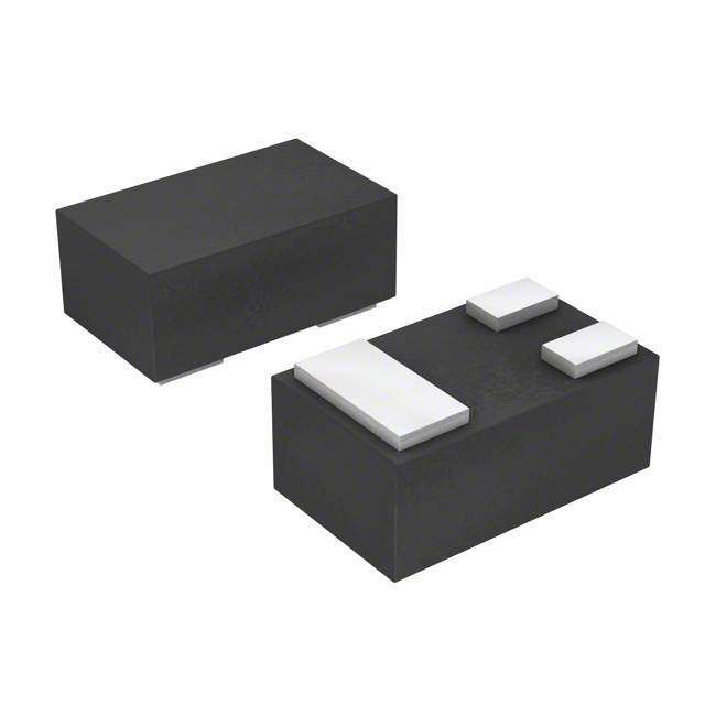
| 产品图片 |
|
| 产品型号 | CDDFN6-0504P |
| PCN组件/产地 | |
| rohs | 无铅 / 符合限制有害物质指令(RoHS)规范要求 |
| 产品系列 | - |
| 不同频率时的电容 | - |
| 供应商器件封装 | 6-DFN (1.6x1.6) |
| 其它名称 | CDDFN6-0504PDKR |
| 功率-峰值脉冲 | 150W |
| 包装 | Digi-Reel® |
| 单向通道 | - |
| 双向通道 | 4 |
| 安装类型 | 表面贴装 |
| 封装/外壳 | 6-PowerUFDFN |
| 工作温度 | -55°C ~ 125°C (TA) |
| 应用 | 以太网 |
| 标准包装 | 1 |
| 电压-击穿(最小值) | 6V |
| 电压-反向关态(典型值) | 5V |
| 电压-箝位(最大值)@Ipp | 12.5V |
| 电流-峰值脉冲(10/1000µs) | 6.5A (8/20µs) |
| 电源线路保护 | 是 |
| 类型 | 转向装置(轨至轨) |


- 商务部:美国ITC正式对集成电路等产品启动337调查
- 曝三星4nm工艺存在良率问题 高通将骁龙8 Gen1或转产台积电
- 太阳诱电将投资9.5亿元在常州建新厂生产MLCC 预计2023年完工
- 英特尔发布欧洲新工厂建设计划 深化IDM 2.0 战略
- 台积电先进制程称霸业界 有大客户加持明年业绩稳了
- 达到5530亿美元!SIA预计今年全球半导体销售额将创下新高
- 英特尔拟将自动驾驶子公司Mobileye上市 估值或超500亿美元
- 三星加码芯片和SET,合并消费电子和移动部门,撤换高东真等 CEO
- 三星电子宣布重大人事变动 还合并消费电子和移动部门
- 海关总署:前11个月进口集成电路产品价值2.52万亿元 增长14.8%


PDF Datasheet 数据手册内容提取
Features Applications NT MPLIA ■ Lead free as standard ■ USB 2.0 & USB OTG HS CO ■ RoHS compliant* ■ Multimedia card interface *Ro ■ Low capacitance - 1.2 pF ■ SD card interface ■ No insertion loss to 2 GHz ■ SIM ports ■ ESD, EFT, surge protection ■ Gigabit Ethernet CDDFN6-0504P - TVS/Steering Diode Array General Information The CDDFN6-0504P device provides ESD, EFT and surge protection for high speed data 5 ports meeting IEC 61000-4-2 (ESD), IEC 61000-4-4 (EFT) and IEC 61000-4-5 (Surge) requirements. The Transient Voltage Suppressor array, protecting up to 4 data lines, offers a Working Peak Reverse Voltage of 5 V and Minimum Breakdown Voltage of 6 V. 1 3 4 6 The molded packaged device will mount directly onto the industry standard DFN6 or QFN6 footprint. Bourns® Chip Diodes are easy to handle with standard pick and place equipment and their fl at confi guration minimizes roll away. GND Absolute Maximum Ratings Parameter Symbol CDDFN6-0504P Unit Peak Pulse Power (tp = 8/20 µs) (NOTE 1) Ppk 150 W Peak Pulse Current (tp = 8/20 µs) (NOTE 1) IPP 6.5 A Storage Temperature TSTG -55 to +150 ºC Operating Temperature TOPR -55 to +125 ºC Operating Supply Voltage VDC 6 V ESD per IEC 61000-4-2 (Air)(I/O to GND) VESD_IO 18 kV ESD per IEC 61000-4-2 (Contact) (I/O to GND) 14 EESSDD ppeerr IIEECC 6611000000--44--22 ((ACior)n(VtaCcCt) (tVoC GCN tDo )GND) VESD_VCC 3300 kV DC Voltage at any I/O Pin VIO (GND-0.5) to (VCC+0.5) V Note 1. See Power Derating Curve. Electrical Characteristics (@ T = 25 °C Unless Otherwise Noted) A Parameter Symbol CDDFN6-0504P Unit Maximum Reverse Standoff Voltage1 VRWM 5.0 V Maximum Leakage Current1 @ VRWM ID 5.0 µA Maximum Channel Leakage Current @ VRWM ICD 1.0 µA Minimum Reverse Breakdown Voltage1 @ IBV=1 mA VBR 6.0 V Maximum Forward Voltage4 @ IF = 15 mA VF 1.0 V Typical Clamping Voltage2 VC 8.1 V Typical ESD Clamping Voltage - I/O per IEC 61000-4-2 +6 kV, Contact2 Vclamp_io 12.5 V Typical ESD Clamping Voltage-VCC1 Vclamp_VCC 9.0 V Maximum Channel Input Capacitance2 @ VPIN5=5 V, VPIN2=0 V, VIN=2.5 V, f=1 MHz CIN 1.6 pF Maximum Channel to Channel Input Capacitance3 @ VPIN5=5 V, VPIN2=0 V, CCROSS 0.14 pF VIN=2.5 V, f=1 MHz Maximum Variation of Channel Input Capacitance @ VPIN5=5 V, VPIN2=0 V, VIN=2.5 ΔCIN 0.06 pF V, f=1 MHz. (I/O Pin to GND) Note 1. Pin 5 to Pin 2 (ground). Note 2. Pin 1, 3, 4 or 6 to Pin 2 (ground). *RoHS Directive 2002/95/EC Jan 27, 2003 including Annex. Note 3. Between any two of pins 1, 3, 4, 6. Specifi cations are subject to change without notice. Note 4. Pin 2 (ground) to Pin 5. Customers should verify actual device performance in their specifi c applications.
CDDFN6-0504P - TVS/Steering Diode Array Product Dimensions Recommended Footprint This is a molded DFN6 package with lead free Nickel-Paladium- 0.50 Gold (Ni/Pd/Au) on the lead frame. It has a fl ammability rating of (.020) 0.35 UL 94V-0. (.014) 1.60 ± 0.05 (0.063 ± 0.002) 2.15 0.45 (.085) (.018) 0.89 1.52 (.035) (.060) DATE CODE 54 1.60 ± 0.05 PIN 1 INDICATOR (0.063 ± 0.002) XX (LASER MARK) 0.63 (.025) 1.30 (.051) 0.25 ± 0.05 0.50 ± 0.05 (.010 ± .002) 5 PLCS. (0.020 ± 0.002) Typical Part Marking CDDFN6-0504P ............................................................................54 0.25 ± 0.05 (.010 ± .002) 5 PLCS. How to Order 0.6 ± 0.05 (0.024 ± 0.002) CD DFN-6 - 05 04P 1.1 ± 0.05 Common Diode (0.043 ± 0.002) Chip Diode Package DFN-6 = DFN-6 Package Working Peak Reverse Voltage 05 = 5 VRWM (Volts) Number of Lines 0.203 ± 0.05 0.55 ± 0.05 04P = 4 Data Lines (0.008 ± 0.002) (0.022 ± 0.002) DIMENSIONS: MM Typical Application (INCHES) TO I/O 1 DATA LINE I/O 1 TO I/O-PORT PROTECTED Pin Out CONNECTOR DATA LINE IC I/O 2 I/O 2 Pin Function 1 6 VDD RAIL 1 I/O GND RAIL 2 GND 2 5 *OPTIONAL 0.1 µF 3 I/O 3 4 CHIP CAP. 4 I/O TO I/O 3 I/O 3 TO 5 V I/O-PORT DATA LINE PROTECTED CC 6 I/O CONNECTOR I/O 4 DATA LINE I/O 4 IC Center Tab GND Specifi cations are subject to change without notice. Customers should verify actual device performance in their specifi c applications.
CDDFN6-0504P - TVS/Steering Diode Array Rating & Characteristic Curves Power Derating Curve Pulse Waveform 110 % of Rated Power 13456789000000000 ak Pulse Current (% of I)PP 114680200000 tt td =e tt|TttItdP e =P=s/ t282 W 0µ saµvseform Parameters 12000 I – PePP 200 0 25 50 75 100 125 150 0 5 10 15 20 25 30 TA - Ambient Temperature (°C) t – Time (µs) Clamping Voltage vs. Peak Pulse Current Forward Voltage vs. Forward Current 12 4.0 11 3.5 10 9 3.0 Clamping Voltage (V) 345678 I/O pin to GND pin WPaarvaemfoertmers: Forward Voltage (V) 2211....5050 I/O pin to GND pin WPaarvaemfoertmers: 2 tr = 8 μs 0.5 tr = 8 μs 1 td = 20 μs td = 20 μs 0 0 4.5 5.0 5.5 6.0 6.5 7.0 7.5 4.5 5.0 5.5 6.0 6.5 7.0 7.5 Peak Pulse Current (A) Peak Pulse Current (A) Capacitance vs. Line Voltage Capacitance vs. Temperature 2.0 1.50 1.8 1.45 1.6 1.40 nput Capacitance (pF) 000111......468024 Input Capacitance (pF) 111111......112233050505 I 0.2 VDD = 5 V, GND = 0 V, f = 1 MHz, T = 25 °C 1.05 VDD = 6 V, GND = 0 V, VIN = 2.5 V, f = 1 MHz 0.0 1.00 0 1 2 3 4 5 20 40 60 80 100 120 Input Voltage (V) Temperature (°C) Specifi cations are subject to change without notice. Customers should verify actual device performance in their specifi c applications.
CDDFN6-0504P - TVS/Steering Diode Array Packaging Information The product will be dispensed in tape and reel format (see diagram below). P 0 P1 E T d Index Hole 120 ° F D2 W B D1 D P A C Trailer Device Leader ....... ....... ....... ....... W1 End ....... ....... ....... ....... Start MM DIMENSIONS: (INCHES) 10 pitches (min.) 10 pitches (min.) Devices are packed in accordance with EIA standard Direction of Feed RS-481-A. Item Symbol DFN-6 1.78 ± 0.05 Carrier Width A (0.070 ± 0.002) 1.78 ± 0.05 Carrier Length B (0.070 ± 0.002) 0.69 ± 0.05 Carrier Depth C (0.027 ± 0.002) 1.55 ± 0.05 Sprocket Hole d (0.061 ± 0.002) 178 Reel Outside Diameter D (7.008) 50.0 Reel Inner Diameter D1 (1.969) MIN. 13.0 ± 0.20 Feed Hole Diameter D2 (0.512 ± 0.008) 1.75 ± 0.10 Sprocket Hole Position E (0.069 ± 0.004) 3.50 ± 0.05 Punch Hole Position F (0.138 ± 0.002) 4.00 ± 0.10 Punch Hole Pitch P (0.157 ± 0.004) 4.00 ± 0.10 Sprocket Hole Pitch P0 (0.157 ± 0.004) 2.00 ± 0.05 Embossment Center P1 (0.079 ± 0.002) 0.20 ± 0.10 Overall Tape Thickness T (0.008 ± 0.004) 8.00 ± 0.20 Tape Width W (0.315 ± 0.008) 14.4 Reel Width W1 (0.567) MAX. REV. 01/11 Quantity per Reel -- 3000 Specifi cations are subject to change without notice. Customers should verify actual device performance in their specifi c applications.