ICGOO在线商城 > 传感器,变送器 > 光学传感器 - 光断续器 - 槽型 - 逻辑输出 > OPB960T51
 Datasheet下载
- 型号: OPB960T51
- 制造商: OPTEK
- 库位|库存: xxxx|xxxx
- 要求:
| 数量阶梯 | 香港交货 | 国内含税 |
| +xxxx | $xxxx | ¥xxxx |
查看当月历史价格
查看今年历史价格
OPB960T51产品简介:
ICGOO电子元器件商城为您提供OPB960T51由OPTEK设计生产,在icgoo商城现货销售,并且可以通过原厂、代理商等渠道进行代购。 OPB960T51价格参考。OPTEKOPB960T51封装/规格:光学传感器 - 光断续器 - 槽型 - 逻辑输出, Optical Sensor Transmissive 0.125" (3.18mm) PCB Mount。您可以下载OPB960T51参考资料、Datasheet数据手册功能说明书,资料中有OPB960T51 详细功能的应用电路图电压和使用方法及教程。
TT Electronics/Optek Technology 的 OPB960T51 是一款光学传感器,属于光断续器(槽型)- 逻辑输出类型。它通过红外发射器和接收器的组合来检测物体的存在或运动,广泛应用于需要精确位置、速度或计数反馈的场景。以下是其主要应用场景:

 1. 自动化设备
   - 物料传输系统:用于检测传送带上物体的位置或数量。
   - 机器人关节控制:监测机械臂或关节的旋转角度或位置。
   - 包装机:检测包装物品是否到位或进行计数。

 2. 消费电子产品
   - 打印机/复印机:检测纸张的存在、对齐状态或卡纸情况。
   - 光驱/磁盘驱动器:监测光盘或磁盘的插入与移除。

 3. 工业控制
   - 电机编码器:作为增量编码器的一部分,用于测量电机转速或旋转角度。
   - 阀门控制:检测阀门的开闭状态或位置。

 4. 家用电器
   - 洗衣机:检测洗衣桶的旋转速度或水位。
   - 吸尘器:监测刷头的旋转状态或障碍物。

 5. 医疗设备
   - 血液分析仪:检测样本管或试剂瓶的位置。
   - 呼吸机:监测气流阀的开关状态。

 6. 汽车电子
   - 雨刷控制系统:检测雨刷的运行位置。
   - 变速箱:监测齿轮切换状态或位置。

 7. 其他应用
   - 电梯门:检测门的开闭状态。
   - 安防系统:监测门窗的开关状态。
   - 玩具:用于互动式玩具中的动作检测或触发功能。

OPB960T51 的特点包括高灵敏度、低功耗和紧凑设计,适合在狭小空间内使用。其逻辑输出特性使其可以直接与微控制器或其他数字电路连接,简化了信号处理流程。因此,该型号适用于需要快速响应和高精度的各类场景。
| 参数 | 数值 |
| 产品目录 | |
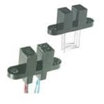
| 描述 | SWITCH SLOTTED OPTICAL WIRE LDS光学开关(透射型,光电IC输出) Slotted Opt Switch Photologic |
| 产品分类 | |
| 品牌 | TT Electronics/Optek Technology |
| 产品手册 | |
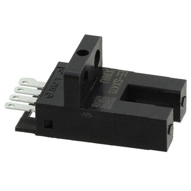
| 产品图片 |
|
| rohs | 符合RoHS无铅 / 符合限制有害物质指令(RoHS)规范要求 |
| 产品系列 | 光学开关(透射型,光电IC输出),Optek / TT Electronics OPB960T51Photologic® |
| 数据手册 | |
| 产品型号 | OPB960T51 |
| 上升时间 | 70 ns |
| 下降时间 | 70 ns |
| 产品种类 | 光学开关(透射型,光电IC输出) |
| 光圈宽度 | 1.27 mm |
| 其它名称 | 365-1790 |
| 反向电压 | 2 V |
| 响应时间 | 70ns |
| 商标 | Optek / TT Electronics |
| 安装类型 | 通孔 |
| 封装 | Bulk |
| 封装/外壳 | PCB 安装 |
| 工厂包装数量 | 25 |
| 感应方式 | Transmissive, Slotted |
| 感应方法 | 可传导的 |
| 感应距离 | 0.125" (3.18mm) |
| 最大工作温度 | + 70 C |
| 最小工作温度 | - 40 C |
| 标准包装 | 25 |
| 槽宽 | 3.18 mm |
| 正向电流 | 40 mA |
| 电压-电源 | 4.75 V ~ 5.25 V |
| 电流-电源 | 15mA |
| 输出设备 | Totem Pole, Buffer |
| 输出配置 | 图腾柱,缓冲器 |


- 商务部:美国ITC正式对集成电路等产品启动337调查
- 曝三星4nm工艺存在良率问题 高通将骁龙8 Gen1或转产台积电
- 太阳诱电将投资9.5亿元在常州建新厂生产MLCC 预计2023年完工
- 英特尔发布欧洲新工厂建设计划 深化IDM 2.0 战略
- 台积电先进制程称霸业界 有大客户加持明年业绩稳了
- 达到5530亿美元!SIA预计今年全球半导体销售额将创下新高
- 英特尔拟将自动驾驶子公司Mobileye上市 估值或超500亿美元
- 三星加码芯片和SET,合并消费电子和移动部门,撤换高东真等 CEO
- 三星电子宣布重大人事变动 还合并消费电子和移动部门
- 海关总署:前11个月进口集成电路产品价值2.52万亿元 增长14.8%


PDF Datasheet 数据手册内容提取
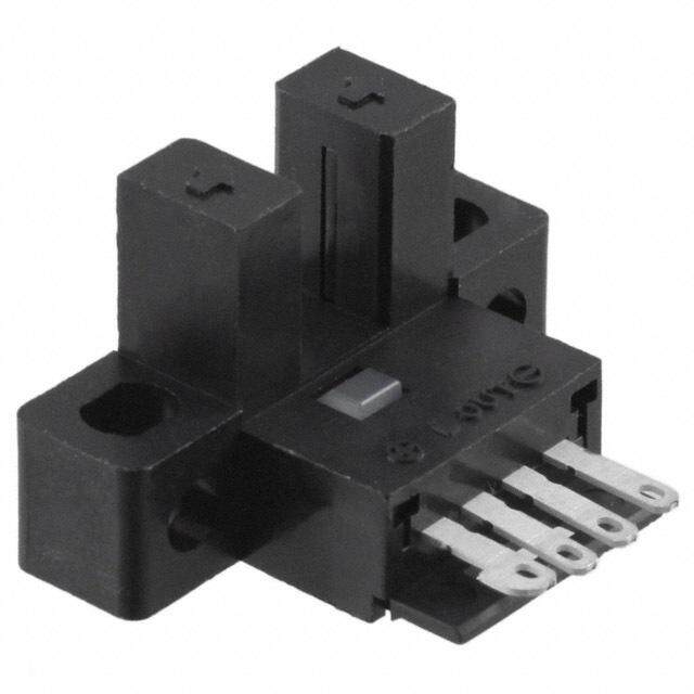
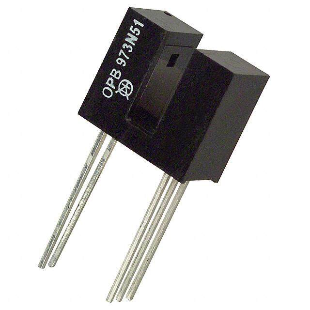
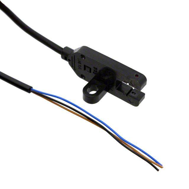
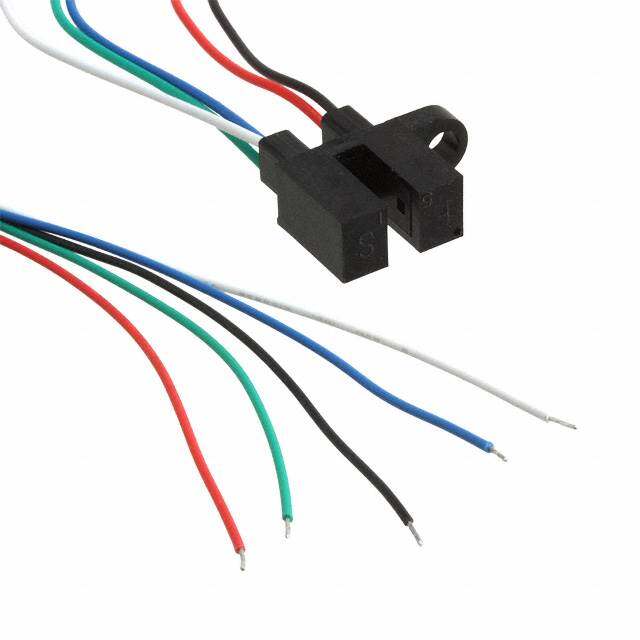
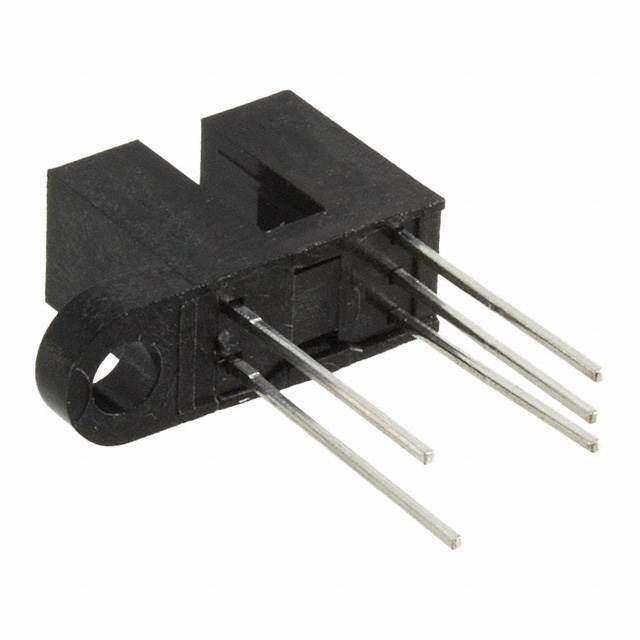
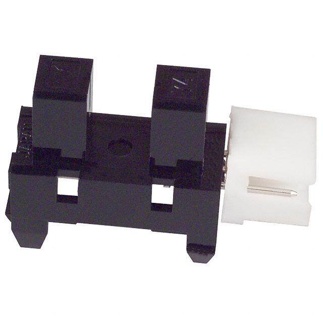
Choice of logic and output driver circuits Choice of aperture size, covered or open Wire or PCB leads Choice of mounting features Direct TTL, LSTTL, CMOS Interface The OPB960/ 970/ 980/ 990 series of non-contact Photologic® slotted optical switches provides flexibility in meeting application specific requirements for the design engineer. Building from a standard housing with a 0.125” (3.18mm) wide slot, the user can specify output logic state, output driver circuit, aperture width, aperture surface and mounting tab locations. Furthermore, an option of wire or PCB leads allows electrical interface flexibility. The device body is an opaque plastic which minimizes sensitivity to both visible and near-infrared external light sources which may impact operation. Aperture width choices provide different optical resolution for motion sensing. A covered aperture provides dust protection, while an open aperture provides maximum protection against external light sources. Electrical operation is over a wide supply voltage range. LED emissions are near-infrared (850—940nm). Detector digital output logic choices of buffer or inverter with totem-pole or open-collector driver circuit simplify interface for various electrical requirements. Custom electrical, wire and cabling services are available. Contact your local representative or OPTEK for more information. Compliant to EU RoHS Directive 2002/95/EC Speed and direction Mechanical switch replacement Printers - Top of form, End of travel, Home position. indication Mechanical limit indication Sliding Door Automotive and Lift gate applications Rotary encoders Part Number Guide OPB 9XX X XX X OPTEK Assembly Z = Wires only, None for PCB leads ® Photologic Sensor Family Aperture Width Guide Options: 55, 51, 11 ( See Aperture Width Guide ) Slot Aperture Surface and Lead Options: 6 — Covered (apertures not visible), PCB leads 7 — Open (apertures visible), PCB leads Mounting Tab Location: 8 — Covered (apertures not visible), Wires L — Emitter 9 — Open (apertures visible), Wires N — None P — Sensor Logic and Output Driver Types: T — Both (two mounting tabs) 0 — Buffer Totem-Pole 1 — Buffer Open-Collector Input Output Log- Logic Type 2 — Inverter Totem-Pole LED ic State 3 — Inverter Open-Collector Buffer OFF LOW = 0 RoHS Inverter OFF HIGH = 1
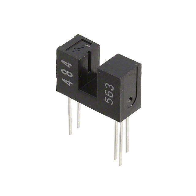
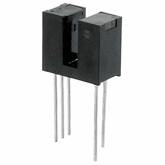
PACKAGE OUTLINE for OPB960 and OPB970 Series APERTURE WIDTH GUIDE TABLE 1 CODE LED SENSOR Lead No. Function 55 .050” [1.27mm] .050” [1.27mm] 51 .050” [1.27mm] .010” [0.25mm] 1 Anode 11 .010” [0.25mm] .010” [0.25mm] 2 Cathode Lengths are .050” [1.27mm] 3 Vcc 4 Output 5 Ground Notes: (1) RMA flux recommended. Duration can be extended to 10 seconds max. (2) Feature controlled at body. (3) Highly activated water soluble fluxes may attack plastic. Recommend trial to verify application. (4) Maximum lead soldering temperature [1.6mm from case for 5 seconds with soldering iron] 260° C. (5) Cathode lead may be shorter. (6) Part number marking may be on any side.
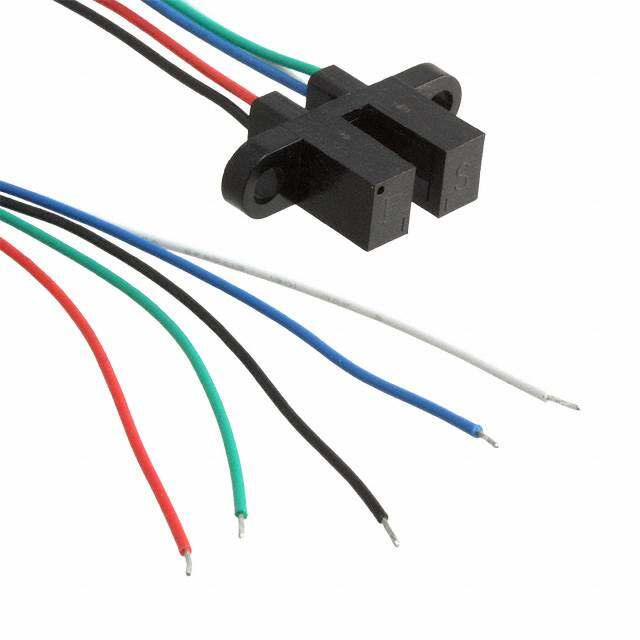
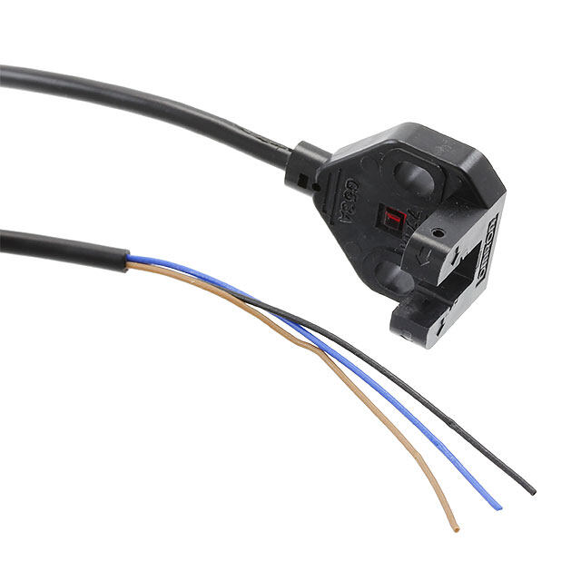
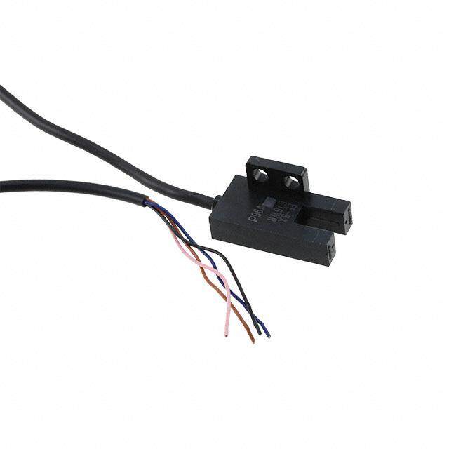
PACKAGE OUTLINE for OPB980 and OPB990 Series APERTURE WIDTH GUIDE CODE LED SENSOR TABLE 2 55 .050” [1.27mm] .050” [1.27mm] Wire Color Function 51 .050” [1.27mm] .010” [0.25mm] Red Anode 11 .010” [0.25mm] .010” [0.25mm] Black Cathode Lengths are .050” [1.27mm] White Vcc Blue Output Green Ground Notes: (7) Wire is 26AWG, UL Rated PVC insulation. (8) Ideal torque for bolt or screw 0,45 to 0,68 Nm ( 4 to 6 Lb-in ). (9) When using a thread lock compound, ND Industries ”ND Vibra-Tite® Formula 3” will avoid stress cracking plastic. (10) Plastic is soluble in chlorinated hydrocarbons and ketones. Methanol or isopropanol are recommended as cleaning agents.
Storage Temperature Range -40°C to +85° C Operating Temperature Range -40°C to +70° C Input Diode (E) Input Diode Power Dissipation 100 mW ( 11) Input Diode Forward D.C. Current, T = 25°C 40 mA( 14) A Input Diode Reverse D.C. Voltage, T = 25°C 2 V A Sensor (S) Supply Voltage (V to Ground) 18 V ( 13) CC Output Photologic® Power Dissipation 200 mW ( 12) Voltage at Output Lead (Open-Collector Output), T = 25°C 35V A Short Circuit Output Current to Ground (I ) 1 sec Max. 30 mA OS Notes: (11) Derate linearly 2.22 mW / °C above 25° C. (12) Derate linearly 4.44 mW / °C above 25° C. (13) Prior to 2004 Vcc was limited to 5.5V maximum. (14) Do not connect input diode directly to a voltage source without an external current limiting resistor. Block Diagram Buffer Totem-Pole Buffer Open-Collector OPB960/ OPB970/ OPB980/ OPB990 OPB961/ OPB971/ OPB981/ OPB991 Inverter Open-Collector Inverter Totem-Pole OPB962/ OPB972/ OPB982/ OPB992 OPB963/ OPB973/ OPB983/ OPB993
Input Diode (See OP140 / OP240 LED for additional information) V Forward Voltage - - 1.70 V I = 20 mA, T = 25° C F F A I Reverse Current - - 100 µA V = 2.0 V, T = 25° C R R A Coupled (See OPL560 Detector for additional information) V Operating D.C. Supply Voltage 4.5 - 16 V CC I Supply Current - - 12 mA V = 4.5V to 16V CC CC Low Level Output Voltage: Buffer Totem-Pole OPB960,OPB970 V = 4.5V, I = 12.8mA OPB980,OPB990 CC OL I = 0 mA (14) Buffer Open-Collector OPB961,OPB971 F OPB981,OPB991 V - - 0.4 V OL Inverter Totem-Pole OPB962,OPB972 OPB982,OPB992 V = 4.5V, I = 12.8mA CC OL Inverter Open-Collector OPB963,OPB973 I = 15 mA F OPB983,OPB993 High Level Output Voltage: V = 4.5V to 16V, I = 800µA Buffer Totem-Pole OPB960,OPB970 CC OH I = 15 mA OPB980,OPB990 F V V -2.1 - - V OH CC Inverter Totem-Pole OPB962,OPB972 V = 4.5V to 16V, I = 800µA CC OH OPB982,OPB992 I = 0 mA (14) F High Level Output Current: V = 4.5V to 16V, V = 30V Buffer Open-Collector OPB961,OPB971 CC OH I = 15 mA F OPB981,OPB991 I - - 100 µA OH Inverter Open-Collector OPB963,OPB973 V = 4.5V to 16V, V = 30V CC OH OPB981,OPB991 IF = 0 mA (14) I (+) LED Positive-Going Threshold Current(16) - - 15 mA V = 5.0V, T = 25° C F CC A I (+) / I (-) Hysteresis Ratio - 1.5 - - V = 5.0V F F CC tR, tF Output Rise Time, Output Fall Time - 70 - ns VCC = 5.0V, IF peak= 15 mA, TA = 25° C 100 kHz square wave, C = 10pF max. Propagation Delay Time R = 360 Ω to GND (Totem-Pole) t , t - 5.0 - µs L PLH PHL Low to High, High to Low R = 1KΩ pull-up (Open-Collector) L Notes: 14) Normal application would be with light source blocked, simulated by I = 0 mA. F 15) All parameters are tested using pulse techniques. 16) An increasing current applied to the LED which causes the output logic state to change. For proper application IF(+), LED current, should be more than the stated maximum.
Logic Output vs Left to Right Bocking Distance (X-Axis Blocked) 5.0 VCC = 5 Volts IF = 20mA Buffer Totem-Pole 4.0 ) V ( ut 3.0 Aperture Width 11 p ut O Aperture Width 51 c gi Aperture Width 55 o 2.0 L 1.0 0.0 0.000 0.025 0.050 0.075 0.100 0.125 0.150 0.175 0.200 0.225 0.250 Distance (inches) Logic Output vs Top to Bottom Bocking Distance (Y-Axis Blocked) 5.0 VCC = 5 Volts IF = 20mA 4.0 Buffer Totem-Pole ) V ( ut 3.0 p ut O c gi 2.0 o L 1.0 0.0 0.000 0.025 0.050 0.075 0.100 0.125 0.150 0.175 0.200 0.225 0.250 Distance (inches)
Mouser Electronics Authorized Distributor Click to View Pricing, Inventory, Delivery & Lifecycle Information: T T Electronics: OPB990L11 OPB972T51 OPB972N51 OPB982L51 OPB982L55 OPB982N11 OPB982N51 OPB982N55 OPB982P11 OPB982P51 OPB982P55 OPB982T11 OPB982T55 OPB983L11 OPB983L51 OPB983L55 OPB983N11 OPB983N51 OPB983N55 OPB983P11 OPB983P51 OPB983P55 OPB983T11 OPB983T51 OPB983T55 OPB990L51 OPB990L55 OPB990N11 OPB990N51 OPB990N55 OPB990P11 OPB990P51 OPB990P55 OPB990T11 OPB990T51 OPB990T55 OPB991L11 OPB991L51 OPB991L55 OPB991N11 OPB991N51 OPB992L11 OPB992L51 OPB992L55 OPB992N11 OPB992N51 OPB992N55 OPB993N11 OPB993N51 OPB993N55 OPB993P11 OPB993P51 OPB993P55 OPB993T11 OPB993T51 OPB980L11Z OPB980L51Z OPB980L55Z OPB980N11Z OPB980N51Z OPB980N55Z OPB980P11Z OPB980P51Z OPB980P55Z OPB980T11Z OPB980T51Z OPB980T55Z OPB981L11Z OPB981L51Z OPB981L55Z OPB981N11Z OPB981N51Z OPB981N55Z OPB981P11Z OPB981P51Z OPB981P55Z OPB981T11Z OPB981T51Z OPB981T55Z OPB982L11Z OPB982L51Z OPB982L55Z OPB982N11Z OPB982N51Z OPB982N55Z OPB982P11Z OPB982P51Z OPB982P55Z OPB982T11Z OPB982T51Z OPB982T55Z OPB983L11Z OPB983L51Z OPB983L55Z OPB983N11Z OPB983N51Z OPB983N55Z OPB983P11Z OPB983P51Z OPB983P55Z