ICGOO在线商城 > NRS6010T100MMGFV
 Datasheet下载
- 型号: NRS6010T100MMGFV
- 制造商: TAIYO YUDEN-XENTEK
- 库位|库存: xxxx|xxxx
- 要求:
| 数量阶梯 | 香港交货 | 国内含税 |
| +xxxx | $xxxx | ¥xxxx |
查看当月历史价格
查看今年历史价格
NRS6010T100MMGFV产品简介:
ICGOO电子元器件商城为您提供NRS6010T100MMGFV由TAIYO YUDEN-XENTEK设计生产,在icgoo商城现货销售,并且可以通过原厂、代理商等渠道进行代购。 提供NRS6010T100MMGFV价格参考¥1.31-¥1.31以及TAIYO YUDEN-XENTEKNRS6010T100MMGFV封装/规格参数等产品信息。 你可以下载NRS6010T100MMGFV参考资料、Datasheet数据手册功能说明书, 资料中有NRS6010T100MMGFV详细功能的应用电路图电压和使用方法及教程。
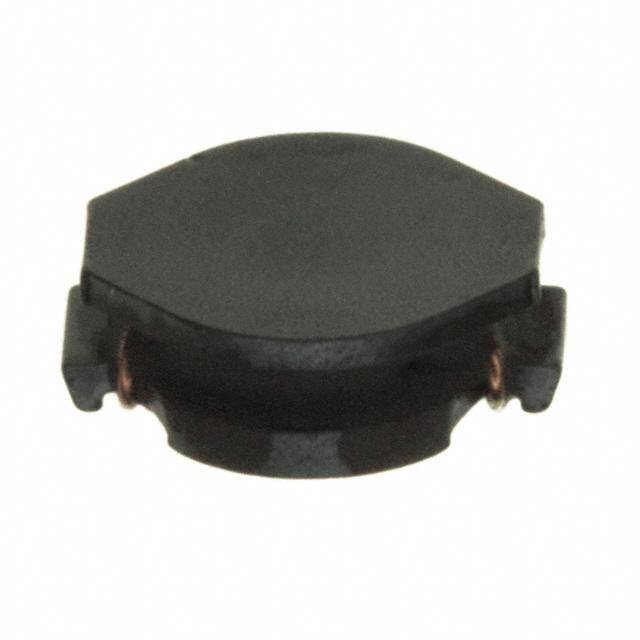
Taiyo Yuden(太阳诱电)NRS6010T100MMGFV是一款高性能功率型固定电感器,属于NRS系列屏蔽式绕线电感,电感值为10μH(±20%),额定电流达4.5A(Isat),直流电阻低至28mΩ(典型值),采用6.0×6.0×1.0mm超薄SMD封装。

其主要应用场景包括:
✅ DC-DC降压转换器(Buck Converter):广泛用于智能手机、平板电脑、笔记本电脑及网络设备的电源管理模块中,作为输出滤波电感,配合PWM控制器(如TI、Richtek、MPS等IC)实现高效稳压;
✅ POL(Point-of-Load)电源系统:适用于FPGA、ASIC、CPU/GPU核心供电等对瞬态响应和低噪声要求严苛的局部供电场景;
✅ 工业与通信设备电源:如基站电源、光模块(SFP+/QSFP)供电、PLC、工控主板等,得益于其高饱和电流、优异的抗EMI屏蔽性能及-40℃~+125℃宽温工作能力;
✅ 汽车电子(符合AEC-Q200 Grade 3):可用于车载信息娱乐系统(IVI)、ADAS摄像头供电、车身控制模块(BCM)等非安全关键类12V/5V/3.3V电源回路(需确认具体批次认证状态)。

该器件具备软饱和特性、低音频噪声、高可靠性及RoHS/REACH合规性,特别适合空间受限且需兼顾效率与稳定性的中高功率密度电源设计。
| 参数 | 数值 |
| 产品目录 | |
| DC电阻(DCR) | 324 毫欧最大 |
| 描述 | INDUCTOR POWER 22UH SMD固定电感器 SMD POWER AEC-Q200 10uH 20% |
| 产品分类 | |
| 品牌 | Taiyo Yuden |
| 产品手册 | http://www.yuden.co.jp/eu/product/category/inductor/NRS6010T100MMGFV.html |
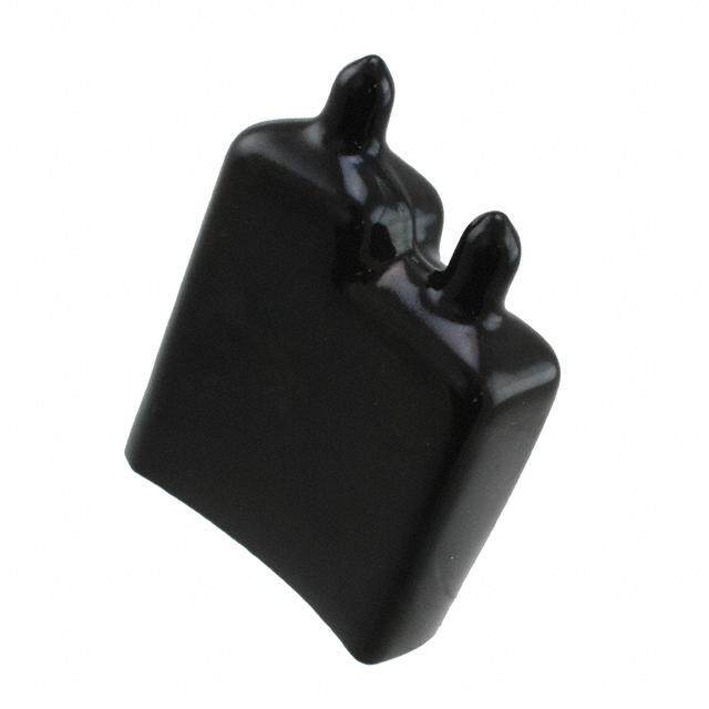
| 产品图片 |
|
| rohs | 符合RoHS无铅 / 符合限制有害物质指令(RoHS)规范要求 |
| 产品系列 | 固定电感器,Taiyo Yuden NRS6010T100MMGFV自动, AEC-Q200, NRS |
| mouser_ship_limit | 该产品可能需要其他文件才能进口到中国。 |
| 数据手册 | |
| 产品型号 | NRS6010T100MMGFV |
| 不同频率时的Q值 | - |
| 产品 | Power Inductors |
| 产品目录绘图 |
|
| 产品种类 | 固定电感器 |
| 供应商器件封装 | - |
| 其它名称 | 587-3612-1 |
| 包装 | 剪切带 (CT) |
| 商标 | Taiyo Yuden |
| 外壳宽度 | 6 mm |
| 外壳长度 | 6 mm |
| 外壳高度 | 1 mm |
| 大小/尺寸 | 0.236" 长 x 0.236" 宽(6.00mm x 6.00mm) |
| 安装类型 | 表面贴装 |
| 容差 | 20 % |
| 封装 | Reel |
| 封装/外壳 | 非标准 |
| 屏蔽 | Unshielded |
| 工作温度 | -40°C ~ 125°C |
| 工作温度范围 | - 40 C to + 125 C |
| 工厂包装数量 | 1000 |
| 最大直流电流 | 1 A |
| 最大直流电阻 | 0.27 Ohms |
| 材料-磁芯 | - |
| 标准包装 | 1 |
| 测试频率 | 100 kHz |
| 电感 | 10 uH |
| 电流-饱和值 | 1A |
| 端接类型 | SMD/SMT |
| 类型 | Industrial/Automotive and Safety |
| 系列 | NR |
| 自谐振频率 | 25 MHz |
| 芯体材料 | Ferrite |
| 频率-测试 | 100kHz |
| 频率-自谐振 | 25MHz |
| 额定电流 | 1.1A |
| 高度-安装(最大值) | 0.039"(1.00mm) |


,NRS6010%20Series%20Bottom.jpg)
,NRS6010%20Series%20Top.jpg)


- 商务部:美国ITC正式对集成电路等产品启动337调查
- 曝三星4nm工艺存在良率问题 高通将骁龙8 Gen1或转产台积电
- 太阳诱电将投资9.5亿元在常州建新厂生产MLCC 预计2023年完工
- 英特尔发布欧洲新工厂建设计划 深化IDM 2.0 战略
- 台积电先进制程称霸业界 有大客户加持明年业绩稳了
- 达到5530亿美元!SIA预计今年全球半导体销售额将创下新高
- 英特尔拟将自动驾驶子公司Mobileye上市 估值或超500亿美元
- 三星加码芯片和SET,合并消费电子和移动部门,撤换高东真等 CEO
- 三星电子宣布重大人事变动 还合并消费电子和移动部门
- 海关总署:前11个月进口集成电路产品价值2.52万亿元 增长14.8%


PDF Datasheet 数据手册内容提取
[ For High Quality and/or Reliability Equipment Notice for TAIYO YUDEN Products (Automotive Electronic Equipment / Industrial Equipment) ] Please read this notice before using the TAIYO YUDEN products. REMINDERS ■ Product information in this catalog is as of October 2018. All of the contents specified herein are subject to change without notice due to technical improvements, etc. Therefore, please check for the latest information carefully before practical application or use of our products. Please note that TAIYO YUDEN shall not be in any way responsible for any damages and defects in products or equipment incorporating our products, which are caused under the conditions other than those specified in this catalog or individual product specification sheets. ■ Please contact TAIYO YUDEN for further details of product specifications as the individual product specification sheets are available. ■ Please conduct validation and verification of our products in actual condition of mounting and operating environment before using our products. ■ The products listed in this catalog are intended for use in general electronic equipment (e.g., AV equipment, OA equipment, home electric appliances, office equipment, information and communication equipment), medical equipment classified as Class I or II by IMDRF, industrial equipment, and automotive interior applications, etc. Please be sure to contact TAIYO YUDEN for further information before using the products for any equipment which may directly cause loss of human life or bodily injury (e.g., transportation equipment including, without limitation, automotive powertrain control system, train control system, and ship control system, traffic signal equipment, medical equipment classified as Class III by IMDRF). Please do not incorporate our products into any equipment requiring high levels of safety and/or reliability (e.g., aerospace equipment, aviation equipment*, medical equipment classified as Class IV by IMDRF, nuclear control equipment, undersea equipment, military equipment). *Note: There is a possibility that our products can be used only for aviation equipment that does not directly affect the safe operation of aircraft (e.g., in-flight entertainment, cabin light, electric seat, cooking equipment) if such use meets requirements specified separately by TAIYO YUDEN. Please be sure to contact TAIYO YUDEN for further information before using our products for such aviation equipment. When our products are used even for high safety and/or reliability-required devices or circuits of general electronic equipment, it is strongly recommended to perform a thorough safety evaluation prior to use of our products and to install a protection circuit as necessary. Please note that unless you obtain prior written consent of TAIYO YUDEN, TAIYO YUDEN shall not be in any way responsible for any damages incurred by you or third parties arising from use of the products listed in this catalog for any equipment requiring inquiry to TAIYO YUDEN or prohibited for use by TAIYO YUDEN as described above. ■ Information contained in this catalog is intended to convey examples of typical performances and/or applications of our products and is not intended to make any warranty with respect to the intellectual property rights or any other related rights of TAIYO YUDEN or any third parties nor grant any license under such rights. ■ Please note that the scope of warranty for our products is limited to the delivered our products themselves and TAIYO YUDEN shall not be in any way responsible for any damages resulting from a fault or defect in our products. Notwithstanding the foregoing, if there is a written agreement (e.g., supply and purchase agreement, quality assurance agreement) signed by TAIYO YUDEN and your company, TAIYO YUDEN will warrant our products in accordance with such agreement. ■ The contents of this catalog are applicable to our products which are purchased from our sales offices or authorized distributors (hereinafter“ TAIYO YUDEN’s official sales channel”). Please note that the contents of this catalog are not applicable to our products purchased from any seller other than TAIYO YUDEN’s official sales channel. ■ Caution for Export Some of our products listed in this catalog may require specific procedures for export according to“ U.S. Export Administration Regulations”,“ Foreign Exchange and Foreign Trade Control Law” of Japan, and other applicable regulations. Should you have any questions on this matter, please contact our sales staff. 19
Automotive Application Guide We classify automotive electronic equipment into the following four application categories and set usable application categories for each of our products. When using our products for automotive electronic equipment, please be sure to check such application categories and use our products accordingly. Should you have any questions on this matter, please contact us. Category Automotive Electronic Equipment (Typical Example) ・Engine ECU (Electronically Controlled Fuel Injector) A ・Cruise Control Unit u t ・4WS (4 Wheel Steering) o m POWERTRAIN ・Automatic Transmission o t ・Power Steering iv e ・HEV/PHV/EV Core Control (Battery, Inverter, DC-DC) A ・Automotive Locator (Car location information providing device), etc. p p ・ABS (Anti-Lock Brake System) lic a ・ESC (Electronic Stability Control) t SAFETY io ・Airbag n ・ADAS (Equipment that directly controls running, turning and stopping), etc. G u ・Wiper id ・Automatic Door e ・Power Window ・Keyless Entry System BODY & CHASSIS ・Electric Door Mirror ・Interior Lighting ・LED Headlight ・TPMS (Tire Pressure Monitoring System) ・Anti-Theft Device (Immobilizer), etc. ・Car Infotainment System ・ITS/Telematics System INFOTAINMENT ・Instrument Cluster ・ADAS (Sensor, Equipment that is not interlocked with safety equipment or powertrain), etc. ▶ This catalog contains the typical specification only due to the limitation of space. When you consider the purchase of our products, please check our product specification sheets. For details of each product (characteristics graph, reliability information, precautions for use, and so on), see our website (http://www.ty-top.com/) . 19 15
SMD POWER INDUCTORS(NR SERIES H TYPE/S TYPE/V TYPE) SMD POWER INDUCTORS (NR SERIES H TYPE/ S TYPE/ V TYPE) REFLOW AEC-Q200 REFLOW AEC-Q200 Grade 3 (we conduct the evaluation at the test condition of Grade 3.) *Operating environment Temp:-40~85℃ AEC-Q200 ■PART NUMBER *Operating Temp. : -40~125℃(Including self-generated heat) N R S 4 0 1 8 T △ 1 0 0 M D G V V △=Blank space ① ② ③ ④ ⑤ ⑥ ⑦ ①Series name ③Packaging Code Series name Code Packaging NRH T△ Taping NRS Coating resin specification NRV ④Nominal inductance IN Code Nominal inductance[μH] D ②Dimensions(L×W×H) (example) U Code Dimensions(L×W×H)[mm] 2R2 2.2 C 2010 2.0×2.0×1.0 100 10 T O 2012 2.0×2.0×1.2 101 100 R 2410 2.4×2.4×1.0 ※R=Decimal point S / 2412 2.4×2.4×1.2 P 3010 3.0×3.0×1.0 ⑤Inductance tolerance O 3012 3.0×3.0×1.2 Code Inductance tolerance W 3015 3.0×3.0×1.5 M ±20% E R 4010 4.0×4.0×1.0 N ±30% IN 4012 4.0×4.0×1.2 D 4018 4.0×4.0×1.8 ⑥Special code U 5010 4.9×4.9×1.0 C 5012 4.9×4.9×1.2 ⑦Internal code T O 5014 4.9×4.9×1.4 Code Internal code R 5020 4.9×4.9×2.0 V Inductor for Industrial and Automotive S 5024 4.9×4.9×2.4 5030 4.9×4.9×3.0 5040 4.9×4.9×4.0 6010 6.0×6.0×1.0 6012 6.0×6.0×1.2 6014 6.0×6.0×1.4 6020 6.0×6.0×2.0 6028 6.0×6.0×2.8 6045 6.0×6.0×4.5 8030 8.0×8.0×3.0 8040 8.0×8.0×4.0 ▶ This catalog contains the typical specification only due to the limitation of space. When you consider the purchase of our products, please check our product specification sheets. For details of each product (characteristics graph, reliability information, precautions for use, and so on), see our website (http://www.ty-top.com/) . 44 19 hq_i_smd_NR_e-E07R01
■STANDARD EXTERNAL DIMENSIONS / STANDARD QUANTITY Recommended Land Patterns L H B Type A B C NRV2010 0.65 1.35 2.0 e NRV2012, NRS2012 C NRH2410 0.7 1.45 2.0 W f NRH2412 NRH3010 NRH3012, NRV3012 0.8 2.2 2.7 e A A NRS3015 NRS4010 NRS4012 1.2 2.8 3.7 NRS4018 NRS8030 1.8 5.6 7.5 NRS8040 Unit:mm Standard quantity Type L W H e f [pcs] Taping 2.0±0.1 2.0±0.1 1.0 max 0.5±0.2 1.25±0.2 IN NRV2010 (0.079±0.004) (0.079±0.004) (0.039 max) (0.020±0.008) (0.050±0.008) 2500 D U NRV2012 2.0±0.1 2.0±0.1 1.2 max 0.5±0.2 1.25±0.2 2500 C NRS2012 (0.079±0.004) (0.079±0.004) (0.047 max) (0.020±0.008) (0.050±0.008) T 2.4±0.1 2.4±0.1 1.0 max 0.6±0.2 1.45±0.2 O NRH2410 (0.095±0.00) (0.095±0.004) (0.039 max) (0.024±0.008) (0.057±0.008) 2500 R S 2.4±0.1 2.4±0.1 1.2 max 0.6±0.2 1.45±0.2 / NRH2412 2500 (0.095±0.004) (0.095±0.004) (0.047 max) (0.024±0.008) (0.057±0.008) P O 3.0±0.1 3.0±0.1 1.0 max 0.9±0.2 1.9±0.2 NRH3010 2000 W (0.118±0.004) (0.118±0.004) (0.039 max) (0.035±0.008) (0.075±0.008) E NRH3012 3.0±0.1 3.0±0.1 1.2 max 0.9±0.2 1.9±0.2 2000 R NRV3012 (0.118±0.004) (0.118±0.004) (0.047 max) (0.035±0.008) (0.075±0.008) IN NRS3015 3.0±0.1 3.0±0.1 1.5 max 0.9±0.2 1.9±0.2 2000 D (0.118±0.004) (0.118±0.004) (0.059 max) (0.035±0.008) (0.075±0.008) U 4.0±0.2 4.0±0.2 1.0 max 1.1±0.2 2.5±0.2 C NRS4010 (0.158±0.008) (0.158±0.008) (0.039 max) (0.043±0.008) (0.098±0.008) 5000 T O NRS4012 4.0±0.2 4.0±0.2 1.2 max 1.1±0.2 2.5±0.2 4500 R (0.158±0.008) (0.158±0.008) (0.047 max) (0.043±0.008) (0.098±0.008) S 4.0±0.2 4.0±0.2 1.8 max 1.1±0.2 2.5±0.2 NRS4018 3500 (0.158±0.008) (0.158±0.008) (0.071 max) (0.043±0.008) (0.098±0.008) 8.0±0.2 8.0±0.2 3.0 max 1.60±0.3 5.6±0.3 NRS8030 1000 (0.315±0.008) (0.315±0.008) (0.118 max) (0.063±0.012) (0.22±0.012) *1) 4.2 max 8.0±0.2 8.0±0.2 (0.165 max) 1.60±0.3 5.6±0.3 NRS8040 1000 (0.315±0.008) (0.315±0.008) *2) 4.0 max (0.063±0.012) (0.22±0.012) (0.158 max) *1) 0R9~6R8 type, *2) 100~101type Unit:mm(inch) hq_i_smd_NR_e-E07R01 ▶ This catalog contains the typical specification only due to the limitation of space. When you consider the purchase of our products, please check our product specification sheets. For details of each product (characteristics graph, reliability information, precautions for use, and so on), see our website (http://www.ty-top.com/) . 19 45
Recommended Land Patterns L H ΔI B Type A B C NRS5010 e NRS5012 C NRS5014 W f NRS5020 1.5 3.6 4.0 NRS5024 NRS5030 e A A NRS5040 NRS6010 NRS6012 NRS6014 1.6 4.7 5.7 NRS6020 NRS6028 NRS6045 Unit:mm Standard quantity Type L W H e f ΔI [pcs] Taping IN 4.9±0.2 4.9±0.2 1.0 max 1.2±0.2 3.3±0.2 1.3typ D NRS5010 1000 (0.193±0.008) (0.193±0.008) (0.039 max) (0.047±0.008) (0.130±0.008) (0.051typ) U C NRS5012 4.9±0.2 4.9±0.2 1.2 max 1.2±0.2 3.3±0.2 1.3typ 1000 T (0.193±0.008) (0.193±0.008) (0.047 max) (0.047±0.008) (0.130±0.008) (0.051typ) O 4.9±0.2 4.9±0.2 1.4 max 1.2±0.2 3.3±0.2 1.3typ R NRS5014 1000 S (0.193±0.008) (0.193±0.008) (0.055 max) (0.047±0.008) (0.130±0.008) (0.051typ) / 4.9±0.2 4.9±0.2 2.0 max 1.2±0.2 3.3±0.2 1.3typ P NRS5020 (0.193±0.008) (0.193±0.008) (0.079 max) (0.047±0.008) (0.130±0.008) (0.051typ) 800 O W *3) 2.5 max 4.9±0.2 4.9±0.2 (0.098 max) 1.2±0.2 3.3±0.2 1.3typ 2500 E NRS5024 R (0.193±0.008) (0.193±0.008) *4) 2.4 max (0.047±0.008) (0.130±0.008) (0.051typ) IN (0.095 max) D *5) 3.1 max U 4.9±0.2 4.9±0.2 (0.122 max) 1.2±0.2 3.3±0.2 1.3typ C NRS5030 (0.193±0.008) (0.193±0.008) *6) 3.0 max (0.047±0.008) (0.130±0.008) (0.051typ) 500 T O (0.118 max) R *7) 4.1 max S 4.9±0.2 4.9±0.2 (0.161 max) 1.2±0.2 3.3±0.2 1.3typ NRS5040 1500 (0.193±0.008) (0.193±0.008) *8) 4.0 max (0.047±0.008) (0.130±0.008) (0.051typ) (0.158 max) 6.0±0.2 6.0±0.2 1.0 max 1.35±0.2 4.0±0.2 2.3typ NRS6010 1000 (0.236±0.008) (0.236±0.008) (0.039 max) (0.053±0.008) (0.158±0.008) (0.091typ) 6.0±0.2 6.0±0.2 1.2 max 1.35±0.2 4.0±0.2 2.3typ NRS6012 1000 (0.236±0.008) (0.236±0.008) (0.047 max) (0.053±0.008) (0.158±0.008) (0.091typ) 6.0±0.2 6.0±0.2 1.4 max 1.35±0.2 4.0±0.2 2.3typ NRS6014 1000 (0.236±0.008) (0.236±0.008) (0.055 max) (0.053±0.008) (0.158±0.008) (0.091typ) 6.0±0.2 6.0±0.2 2.0 max 1.35±0.2 4.0±0.2 2.3typ NRS6020 2500 (0.236±0.008) (0.236±0.008) (0.079 max) (0.053±0.008) (0.158±0.008) (0.091typ) 6.0±0.2 6.0±0.2 2.8 max 1.35±0.2 4.0±0.2 2.3typ NRS6028 2000 (0.236±0.008) (0.236±0.008) (0.110 max) (0.053±0.008) (0.158±0.008) (0.091typ) 6.0±0.2 6.0±0.2 4.5 max 1.35±0.2 4.0±0.2 2.3typ NRS6045 1500 (0.236±0.008) (0.236±0.008) (0.177 max) (0.053±0.008) (0.158±0.008) (0.091typ) *3) 1R0~1R5 type, *4) 2R2~330 type Unit:mm(inch) *5) R47~100 type, *6) 150~470 type *7) 1R5~100 type, *8) 150~470 type hq_i_smd_NR_e-E07R01 ▶ This catalog contains the typical specification only due to the limitation of space. When you consider the purchase of our products, please check our product specification sheets. For details of each product (characteristics graph, reliability information, precautions for use, and so on), see our website (http://www.ty-top.com/) . 46 19
■PART NUMBER ・ All the SMD Power Inductors of the catalog lineup are RoHS compliant. Note) ・ The exchange of individual specifications is necessary depending on the application and circuit condition. Please contact Taiyo Yuden sales channels. ・ *1: Automotive (AEC-Q200 Qualified) products for BODY & CHASSIS, and INFOTAINMENT. Please check ”Automotive Application Guide” for further details before using the products. < A EC - Q 2 00 :AEC-Q200 qualified> All the SMD Power Inductors of *1 marks are tested based on the test conditions and methods defined in AEC-Q200 by family item. Please consult with TAIYO YUDEN’s official sales channel for the details of the product specification and AEC-Q200 test results, etc., and please review and approve TAIYO YUDEN's product specification before ordering. ・ *2: Industrial products and Medical products ●NRV2010 type Self-resonant Rated current ※) [mA] Nominal inductance DC Resistance Measuring Part number [μH] Inductance tolerance frequency [Ω](±20%) Saturation current Temperature rise current frequency[kHz] Note [MHz](min.) Idc1 Idc2 NRV2010T R47N GFV 0.47 ±30% - 0.052 2,100 2,000 100 *1, *2 NRV2010T R68N GFV 0.68 ±30% - 0.060 1,850 1,850 100 *1, *2 NRV2010T 1R0N GFV 1.0 ±30% - 0.080 1,550 1,600 100 *1, *2 NRV2010T 1R5M GFV 1.5 ±20% - 0.100 1,350 1,450 100 *1, *2 NRV2010T 2R2M GFV 2.2 ±20% - 0.175 1,100 1,100 100 *1, *2 NRV2010T 3R3M GFV 3.3 ±20% - 0.250 880 1,000 100 *1, *2 NRV2010T 4R7M GFV 4.7 ±20% - 0.320 760 820 100 *1, *2 IN D ●NRV2012 type U Self-resonant Rated current ※) [mA] C Nominal inductance DC Resistance Measuring Part number [μH] Inductance tolerance frequency [Ω](±20%) Saturation current Temperature rise current frequency[kHz] Note T [MHz](min.) Idc1 Idc2 O NRV2012T 1R0N GFV 1.0 ±30% - 0.073 2,200 1,650 100 *1, *2 R NRV2012T 1R5N GFV 1.5 ±30% - 0.100 1,800 1,400 100 *1, *2 S/ NRV2012T 2R2M GFV 2.2 ±20% - 0.129 1,600 1,200 100 *1, *2 NRV2012T 3R3M GFV 3.3 ±20% - 0.227 1,250 900 100 *1, *2 P O NRV2012T 4R7M GFV 4.7 ±20% - 0.325 1,100 750 100 *1, *2 W ●NRS2012 Shielded type E Self-resonant Rated current ※) [mA] R Nominal inductance DC Resistance Measuring Part number [μH] Inductance tolerance frequency [Ω](±20%) Saturation current Temperature rise current frequency[kHz] Note IN [MHz](min.) Idc1 Idc2 D NRS2012T 1R0N GJV 1.0 ±30% - 0.070 1,900 1,700 100 *1, *2 U NRS2012T 1R5N GJV 1.5 ±30% - 0.090 1,650 1,500 100 *1, *2 C NRS2012T 2R2M GJV 2.2 ±20% - 0.107 1,350 1,370 100 *1, *2 T NRS2012T 3R3M GJV 3.3 ±20% - 0.190 1,000 1,020 100 *1, *2 O NRS2012T 4R7M GJV 4.7 ±20% - 0.241 900 910 100 *1, *2 R S ●NRH2410 Shielded type Self-resonant Rated current ※) [mA] Nominal inductance DC Resistance Measuring Part number [μH] Inductance tolerance frequency [Ω](±20%) Saturation current Temperature rise current frequency[kHz] Note [MHz](min.) Idc1 Idc2 NRH2410T R68NN 4V 0.68 ±30% 120 0.060 2,200 1,570 100 *1, *2 NRH2410T 1R0NN 4V 1.0 ±30% 106 0.070 1,800 1,410 100 *1, *2 NRH2410T 1R5MN V 1.5 ±20% 94 0.110 1,550 1,160 100 *1, *2 NRH2410T 2R2MN V 2.2 ±20% 77 0.150 1,290 970 100 *1, *2 NRH2410T 3R3MN V 3.3 ±20% 56 0.220 1,000 770 100 *1, *2 NRH2410T 4R7MN V 4.7 ±20% 50 0.290 880 670 100 *1, *2 NRH2410T 6R8MN V 6.8 ±20% 43 0.410 750 570 100 *1, *2 NRH2410T 100MN V 10 ±20% 32 0.690 550 450 100 *1, *2 NRH2410T 150MN V 15 ±20% 27 1.02 470 370 100 *1, *2 NRH2410T 220MN V 22 ±20% 22 1.47 390 300 100 *1, *2 ●NRH2412 Shielded type Self-resonant Rated current ※) [mA] Nominal inductance DC Resistance Measuring Part number [μH] Inductance tolerance frequency [Ω](±20%) Saturation current Temperature rise current frequency[kHz] Note [MHz](min.) Idc1 Idc2 NRH2412T R47NNGJV 0.47 ±30% 180 0.050 2,900 2,100 100 *1, *2 NRH2412T 1R0NNGHV 1.0 ±30% 101 0.077 2,350 1,300 100 *1, *2 NRH2412T 1R5NNGHV 1.5 ±30% 89 0.100 2,100 1,150 100 *1, *2 NRH2412T 2R2MNGHV 2.2 ±20% 72 0.140 1,700 1,000 100 *1, *2 NRH2412T 3R3MNGHV 3.3 ±20% 56 0.225 1,400 750 100 *1, *2 NRH2412T 4R7MNGHV 4.7 ±20% 45 0.300 1,150 650 100 *1, *2 NRH2412T 6R8MNGHV 6.8 ±20% 34 0.420 950 550 100 *1, *2 NRH2412T 100MNGHV 10 ±20% 29 0.600 810 450 100 *1, *2 ※) The saturation current value (Idc1) is the DC current value having inductance decrease down to 30%. (at 20℃) ※) The temperature rise current value(Idc2) is the DC current value having temperature increase up to 40℃. (at 20℃) ※) The rated current is the DC current value that satisfies both of current value saturation current value and temperature rise current value. hq_i_smd_NR_e-E07R01 ▶ This catalog contains the typical specification only due to the limitation of space. When you consider the purchase of our products, please check our product specification sheets. For details of each product (characteristics graph, reliability information, precautions for use, and so on), see our website (http://www.ty-top.com/) . 19 47
■PART NUMBER ●NRH3010 Shielded type Self-resonant Rated current ※) [mA] Nominal inductance DC Resistance Measuring Part number [μH] Inductance tolerance frequency [Ω](±20%) Saturation current Temperature rise current frequency[kHz] Note [MHz](min.) Idc1 Idc2 NRH3010T 1R2NN V 1.2 ±30% 120 0.065 1,700 1,480 100 *1, *2 NRH3010T 1R5NN V 1.5 ±30% 99 0.075 1,440 1,370 100 *1, *2 NRH3010T 2R2MN V 2.2 ±20% 86 0.083 1,300 1,300 100 *1, *2 NRH3010T 3R3MN V 3.3 ±20% 64 0.130 1,000 1,030 100 *1, *2 NRH3010T 4R7MN V 4.7 ±20% 50 0.170 850 900 100 *1, *2 NRH3010T 6R8MN V 6.8 ±20% 44 0.250 700 745 100 *1, *2 NRH3010T 100MN V 10 ±20% 34 0.350 600 620 100 *1, *2 NRH3010T 150MN V 15 ±20% 25 0.550 450 480 100 *1, *2 NRH3010T 220MN V 22 ±20% 22 0.770 380 410 100 *1, *2 NRH3010T 470MN V 47 ±20% 17 2.05 250 285 100 *1, *2 ●NRH3012 Shielded type Self-resonant Rated current ※) [mA] Nominal inductance DC Resistance Measuring Part number [μH] Inductance tolerance frequency [Ω](±20%) Saturation current Temperature rise current frequency[kHz] Note [MHz](min.) Idc1 Idc2 NRH3012T R47NN V 0.47 ±30% 160 0.033 2,600 1,900 100 *1, *2 NRH3012T 1R0NN V 1.0 ±30% 111 0.048 2,200 1,710 100 *1, *2 NRH3012T 1R5NN V 1.5 ±30% 95 0.055 1,700 1,600 100 *1, *2 NRH3012T 2R2MN V 2.2 ±20% 78 0.075 1,500 1,370 100 *1, *2 IN NRH3012T 3R3MN V 3.3 ±20% 61 0.100 1,200 1,210 100 *1, *2 D NRH3012T 4R7MN V 4.7 ±20% 50 0.130 1,000 1,060 100 *1, *2 U NRH3012T 6R8MN V 6.8 ±20% 43 0.190 850 890 100 *1, *2 C NRH3012T 100MN V 10 ±20% 32 0.270 730 720 100 *1, *2 T NRH3012T 150MN V 15 ±20% 26 0.450 530 570 100 *1, *2 O NRH3012T 220MN V 22 ±20% 22 0.630 500 500 100 *1, *2 R S ●NRV3012 Shielded type / Self-resonant Rated current ※) [mA] PO Part number Nomina[lμ inHdu]ctance Inductance tolerance [MfrHeqzu]e(nmciny.) D[ΩC ]R(e±sis2t0a%nc)e SaturatIidocn1 current TemperatuIrdec r2ise current freqMueeanscuyr[inkgHz] Note W NRV3012T 1R0N V 1.0 ±30% 110 0.065 2,500 1,600 100 *1, *2 E NRV3012T 1R5N V 1.5 ±30% 92 0.075 2,100 1,400 100 *1, *2 R NRV3012T 2R2M V 2.2 ±20% 70 0.120 1,800 1,100 100 *1, *2 IN NRV3012T 3R3M V 3.3 ±20% 55 0.150 1,600 1,000 100 *1, *2 NRV3012T 4R7M V 4.7 ±20% 48 0.190 1,250 850 100 *1, *2 D NRV3012T 6R8M V 6.8 ±20% 40 0.300 950 650 100 *1, *2 U NRV3012T 100M V 10 ±20% 32 0.470 800 550 100 *1, *2 C T O ●NRS3015 Shielded type R Nominal inductance Self-resonant DC Resistance Rated current ※) [mA] Measuring S Part number [μH] Inductance tolerance frequency [Ω](±20%) Saturation current Temperature rise current frequency[kHz] Note [MHz](min.) Idc1 Idc2 NRS3015T 1R0NNGHV 1.0 ±30% 100 0.030 2,100 2,100 100 *1, *2 NRS3015T 1R5NNGHV 1.5 ±30% 87 0.038 1,800 1,820 100 *1, *2 NRS3015T 2R2MNGHV 2.2 ±20% 64 0.058 1,480 1,500 100 *1, *2 NRS3015T 3R3MNGHV 3.3 ±20% 49 0.078 1,210 1,230 100 *1, *2 NRS3015T 4R7MNGHV 4.7 ±20% 40 0.120 1,020 1,040 100 *1, *2 NRS3015T 6R8MNGHV 6.8 ±20% 36 0.160 870 880 100 *1, *2 NRS3015T 100MNGHV 10 ±20% 28 0.220 700 710 100 *1, *2 NRS3015T 220MNGHV 22 ±20% 20 0.520 470 470 100 *1, *2 ●NRS4010 Shielded type Self-resonant Rated current ※) [mA] Nominal inductance DC Resistance Measuring Part number [μH] Inductance tolerance frequency [Ω](±20%) Saturation current Temperature rise current frequency[kHz] Note [MHz](min.) Idc1 Idc2 NRS4010T 1R0NDGGV 1.0 ±30% 116 0.056 2,000 1,900 100 *1, *2 NRS4010T 2R2MDGGV 2.2 ±20% 73 0.085 1,200 1,500 100 *1, *2 NRS4010T 3R3MDGGV 3.3 ±20% 58 0.100 1,100 1,400 100 *1, *2 NRS4010T 4R7MDGGV 4.7 ±20% 47 0.140 950 1,200 100 *1, *2 NRS4010T 6R8MDGGV 6.8 ±20% 38 0.200 800 1,000 100 *1, *2 NRS4010T 100MDGGV 10 ±20% 31 0.300 620 750 100 *1, *2 NRS4010T 150MDGGV 15 ±20% 24 0.430 540 600 100 *1, *2 NRS4010T 220MDGGV 22 ±20% 19 0.570 450 500 100 *1, *2 ●NRS4012 Shielded type Self-resonant Rated current ※) [mA] Nominal inductance DC Resistance Measuring Part number [μH] Inductance tolerance frequency [Ω](±20%) Saturation current Temperature rise current frequency[kHz] Note [MHz](min.) Idc1 Idc2 NRS4012T 1R0NDGGV 1.0 ±30% 100 0.042 2,800 2,200 100 *1, *2 NRS4012T 2R2MDGJV 2.2 ±20% 70 0.060 1,650 1,900 100 *1, *2 NRS4012T 3R3MDGJV 3.3 ±20% 60 0.070 1,400 1,700 100 *1, *2 NRS4012T 4R7MDGJV 4.7 ±20% 45 0.095 1,200 1,500 100 *1, *2 NRS4012T 6R8MDGJV 6.8 ±20% 35 0.125 900 1,300 100 *1, *2 NRS4012T 100MDGJV 10 ±20% 30 0.170 800 1,100 100 *1, *2 NRS4012T 150MDGJV 15 ±20% 24 0.260 650 750 100 *1, *2 NRS4012T 220MDGJV 22 ±20% 18 0.400 500 620 100 *1, *2 ※) The saturation current value (Idc1) is the DC current value having inductance decrease down to 30%. (at 20℃) ※) The temperature rise current value(Idc2) is the DC current value having temperature increase up to 40℃. (at 20℃) ※) The rated current is the DC current value that satisfies both of current value saturation current value and temperature rise current value. hq_i_smd_NR_e-E07R01 ▶ This catalog contains the typical specification only due to the limitation of space. When you consider the purchase of our products, please check our product specification sheets. For details of each product (characteristics graph, reliability information, precautions for use, and so on), see our website (http://www.ty-top.com/) . 48 19
■PART NUMBER ●NRS4018 Shielded type Self-resonant Rated current ※) [mA] Nominal inductance DC Resistance Measuring Part number [μH] Inductance tolerance frequency [Ω](±20%) Saturation current Temperature rise current frequency[kHz] Note [MHz](min.) Idc1 Idc2 NRS4018T 1R0NDGJV 1.0 ±30% 90 0.027 4,000 3,200 100 *1, *2 NRS4018T 1R5NDGJV 1.5 ±30% 75 0.037 3,300 2,400 100 *1, *2 NRS4018T 2R2MDGJV 2.2 ±20% 60 0.042 3,000 2,200 100 *1, *2 NRS4018T 3R3MDGJV 3.3 ±20% 45 0.055 2,300 2,000 100 *1, *2 NRS4018T 4R7MDGJV 4.7 ±20% 35 0.070 2,000 1,700 100 *1, *2 NRS4018T 6R8MDGJV 6.8 ±20% 30 0.098 1,600 1,450 100 *1, *2 NRS4018T 100MDGJV 10 ±20% 25 0.150 1,300 1,200 100 *1, *2 NRS4018T 150MDGJV 15 ±20% 18 0.210 1,100 850 100 *1, *2 NRS4018T 220MDGJV 22 ±20% 15 0.290 900 720 100 *1, *2 NRS4018T 330MDGJV 33 ±20% 12 0.460 700 550 100 *1, *2 NRS4018T 470MDGJV 47 ±20% 10 0.650 600 440 100 *1, *2 NRS4018T 680MDGJV 68 ±20% 8.3 1.00 520 320 100 *1, *2 NRS4018T 101MDGJV 100 ±20% 6.5 1.45 420 280 100 *1, *2 NRS4018T 151MDGJV 150 ±20% 5.5 2.30 340 220 100 *1, *2 NRS4018T 221MDGJV 220 ±20% 4.0 3.80 275 170 100 *1, *2 ●NRS5010 type Self-resonant Rated current ※) [mA] Nominal inductance DC Resistance Measuring Part number [μH] Inductance tolerance frequency [Ω](±20%) Saturation current Temperature rise current frequency[kHz] Note [MHz](min.) Idc1 Idc2 IN NRS5010T 1R0NMGFV 1.0 ±30% 95 0.070 2,350 1,750 100 *1, *2 D NRS5010T 2R2NMGFV 2.2 ±30% 65 0.105 1,500 1,400 100 *1, *2 U NRS5010T 3R3MMGFV 3.3 ±20% 42 0.125 1,400 1,250 100 *1, *2 C NRS5010T 4R7MMGFV 4.7 ±20% 37 0.145 1,200 1,150 100 *1, *2 T NRS5010T 6R8MMGFV 6.8 ±20% 33 0.185 1,000 1,000 100 *1, *2 O NRS5010T 100MMGFV 10 ±20% 23 0.250 850 900 100 *1, *2 R NRS5010T 150MMGFV 15 ±20% 19 0.400 680 650 100 *1, *2 S / NRS5010T 220MMGFV 22 ±20% 15 0.600 550 450 100 *1, *2 P O ●NRS5012 type Self-resonant Rated current ※) [mA] W Nominal inductance DC Resistance Measuring Part number [μH] Inductance tolerance frequency [Ω](±20%) Saturation current Temperature rise current frequency[kHz] Note E [MHz](min.) Idc1 Idc2 R NRS5012T 1R0NMGFV 1.0 ±30% 100 0.053 4,500 2,300 100 *1, *2 IN NRS5012T 1R5NMGFV 1.5 ±30% 86 0.070 3,800 2,200 100 *1, *2 D NRS5012T 2R2MMGFV 2.2 ±20% 70 0.085 3,100 2,000 100 *1, *2 U NRS5012T 3R3MMGFV 3.3 ±20% 48 0.160 2,400 1,450 100 *1, *2 C NRS5012T 4R7MMGFV 4.7 ±20% 40 0.180 2,200 1,400 100 *1, *2 T NRS5012T 6R8MMGFV 6.8 ±20% 36 0.260 1,700 1,100 100 *1, *2 O NRS5012T 100MMGFV 10 ±20% 26 0.420 1,400 850 100 *1, *2 R NRS5012T 150MMGFV 15 ±20% 22 0.670 1,200 640 100 *1, *2 S ●NRS5014 Shielded type Self-resonant Rated current ※) [mA] Nominal inductance DC Resistance Measuring Part number [μH] Inductance tolerance frequency [Ω](±20%) Saturation current Temperature rise current frequency[kHz] Note [MHz](min.) Idc1 Idc2 NRS5014T R47NMGGV 0.47 ±30% 185 0.025 5,800 3,300 100 *1, *2 NRS5014T 1R2NMGGV 1.2 ±30% 86 0.045 3,800 2,400 100 *1, *2 NRS5014T 2R2NMGGV 2.2 ±30% 56 0.065 2,800 2,000 100 *1, *2 NRS5014T 3R3NMGGV 3.3 ±30% 48 0.080 2,350 1,700 100 *1, *2 NRS5014T 4R7NMGGV 4.7 ±30% 41 0.100 2,050 1,400 100 *1, *2 NRS5014T 6R8MMGGV 6.8 ±20% 33 0.150 1,600 1,200 100 *1, *2 NRS5014T 100MMGGV 10 ±20% 27 0.200 1,400 1,050 100 *1, *2 NRS5014T 150MMGGV 15 ±20% 20 0.320 1,100 650 100 *1, *2 NRS5014T 220MMGGV 22 ±20% 16 0.450 900 550 100 *1, *2 ●NRS5020 Shielded type Self-resonant Rated current ※) [mA] Nominal inductance DC Resistance Measuring Part number [μH] Inductance tolerance frequency [Ω](±20%) Saturation current Temperature rise current frequency[kHz] Note [MHz](min.) Idc1 Idc2 NRS5020T R47NMGJV 0.47 ±30% 230 0.012 6,100 5,000 100 *1, *2 NRS5020T 1R0NMGJV 1.0 ±30% 81 0.021 4,000 3,600 100 *1, *2 NRS5020T 1R5NMGJV 1.5 ±30% 68 0.026 3,350 3,200 100 *1, *2 NRS5020T 2R2NMGJV 2.2 ±30% 57 0.035 2,900 2,900 100 *1, *2 NRS5020T 3R3NMGJV 3.3 ±30% 46 0.048 2,400 2,400 100 *1, *2 NRS5020T 4R7MMGJV 4.7 ±20% 37 0.060 2,000 2,000 100 *1, *2 NRS5020T 6R8MMGJV 6.8 ±20% 30 0.090 1,600 1,650 100 *1, *2 NRS5020T 100MMGJV 10 ±20% 24 0.120 1,300 1,450 100 *1, *2 NRS5020T 150MMGJV 15 ±20% 20 0.165 1,100 1,200 100 *1, *2 NRS5020T 220MMGJV 22 ±20% 17 0.260 900 1,000 100 *1, *2 NRS5020T 470MMGJV 47 ±20% 12 0.435 630 560 100 *1, *2 NRS5020T 101MMGJV 100 ±20% 7 0.850 420 400 100 *1, *2 ※) The saturation current value (Idc1) is the DC current value having inductance decrease down to 30%. (at 20℃) ※) The temperature rise current value(Idc2) is the DC current value having temperature increase up to 40℃. (at 20℃) ※) The rated current is the DC current value that satisfies both of current value saturation current value and temperature rise current value. hq_i_smd_NR_e-E07R01 ▶ This catalog contains the typical specification only due to the limitation of space. When you consider the purchase of our products, please check our product specification sheets. For details of each product (characteristics graph, reliability information, precautions for use, and so on), see our website (http://www.ty-top.com/) . 19 49
■PART NUMBER ●NRS5024 Shielded type Self-resonant Rated current ※) [mA] Nominal inductance DC Resistance Measuring Part number [μH] Inductance tolerance frequency [Ω](±20%) Saturation current Temperature rise current frequency[kHz] Note [MHz](min.) Idc1 Idc2 NRS5024T 1R0NMGJV 1.0 ±30% 85 0.016 5,800 4,400 100 *1, *2 NRS5024T 1R5NMGJV 1.5 ±30% 67 0.022 5,200 3,600 100 *1, *2 NRS5024T 2R2NMGJV 2.2 ±30% 51 0.029 4,100 3,100 100 *1, *2 NRS5024T 3R3NMGJV 3.3 ±30% 41 0.043 3,100 2,400 100 *1, *2 NRS5024T 4R7MMGJV 4.7 ±20% 37 0.055 2,700 2,000 100 *1, *2 NRS5024T 6R8MMGJV 6.8 ±20% 28 0.080 2,200 1,600 100 *1, *2 NRS5024T 100MMGJV 10 ±20% 21 0.125 1,700 1,200 100 *1, *2 NRS5024T 150MMGJV 15 ±20% 18 0.170 1,400 1,000 100 *1, *2 NRS5024T 220MMGJV 22 ±20% 15 0.230 1,200 820 100 *1, *2 NRS5024T 330MMGJV 33 ±20% 11 0.370 1,000 630 100 *1, *2 ●NRS5030 Shielded type Self-resonant Rated current ※) [mA] Nominal inductance DC Resistance Measuring Part number [μH] Inductance tolerance frequency [Ω](±30%) Saturation current Temperature rise current frequency[kHz] Note [MHz](min.) Idc1 Idc2 NRS5030T R47NMGJV 0.47 ±30% 185 0.010 9,000 5,000 100 *1, *2 NRS5030T 1R0NMGJV 1.0 ±30% 110 0.015 6,600 4,000 100 *1, *2 NRS5030T 2R2NMGJV 2.2 ±30% 46 0.023 4,200 3,500 100 *1, *2 NRS5030T 3R3MMGJV 3.3 ±20% 36 0.030 3,600 3,000 100 *1, *2 IN NRS5030T 4R7MMGJV 4.7 ±20% 31 0.035 3,100 2,600 100 *1, *2 D NRS5030T 6R8MMGJV 6.8 ±20% 22 0.052 2,500 2,300 100 *1, *2 U NRS5030T 100MMGJV 10 ±20% 20 0.070 2,100 1,700 100 *1, *2 C NRS5030T 150MMGJV 15 ±20% 14 0.125 1,600 1,400 100 *1, *2 T NRS5030T 220MMGJV 22 ±20% 13 0.180 1,400 1,050 100 *1, *2 O NRS5030T 330MMGJV 33 ±20% 10 0.225 1,150 800 100 *1, *2 R NRS5030T 470MMGJV 47 ±20% 9 0.325 950 700 100 *1, *2 S / ●NRS5040 Shielded type P Self-resonant Rated current ※) [mA] OW Part number Nomina[lμ inHdu]ctance Inductance tolerance [MfrHeqzu]e(nmciny.) D[ΩC ]R(e±sis3t0a%nc)e SaturatIidocn1 current TemperatuIrdec r2ise current freqMueeanscuyr[inkgHz] Note E NRS5040T 1R5NMGJV 1.5 ±30% 60 0.017 6,400 4,500 100 *1, *2 R NRS5040T 2R2NMGJV 2.2 ±30% 42 0.022 5,000 3,700 100 *1, *2 IN NRS5040T 3R3NMGJV 3.3 ±30% 32 0.027 4,000 3,300 100 *1, *2 NRS5040T 4R7NMGKV 4.7 ±30% 28 0.029 3,300 3,100 100 *1, *2 D NRS5040T 6R8MMGJV 6.8 ±20% 21 0.049 2,800 2,400 100 *1, *2 U NRS5040T 100MMGJV 10 ±20% 18 0.056 2,300 2,100 100 *1, *2 C NRS5040T 150MMGJV 15 ±20% 13 0.080 2,000 1,800 100 *1, *2 T O NRS5040T 220MMGKV 22 ±20% 9 0.126 1,500 1,400 100 *1, *2 NRS5040T 330MMGJV 33 ±20% 7 0.180 1,300 1,200 100 *1, *2 R S NRS5040T 470MMGJV 47 ±20% 6 0.310 1,100 900 100 *1, *2 ●NRS6010 type Self-resonant Rated current ※) [mA] Nominal inductance DC Resistance Measuring Part number [μH] Inductance tolerance frequency [Ω](±20%) Saturation current Temperature rise current frequency[kHz] Note [MHz](min.) Idc1 Idc2 NRS6010T 1R5MMGFV 1.5 ±20% 77 0.090 2,400 1,900 100 *1, *2 NRS6010T 2R2MMGFV 2.2 ±20% 56 0.110 1,900 1,700 100 *1, *2 NRS6010T 3R3MMGFV 3.3 ±20% 42 0.135 1,600 1,500 100 *1, *2 NRS6010T 4R7MMGFV 4.7 ±20% 36 0.165 1,300 1,400 100 *1, *2 NRS6010T 6R8MMGFV 6.8 ±20% 30 0.220 1,200 1,200 100 *1, *2 NRS6010T 100MMGFV 10 ±20% 25 0.270 1,000 1,100 100 *1, *2 NRS6010T 220MMGFV 22 ±20% 12 0.580 650 700 100 *1, *2 ●NRS6012 Shielded type Self-resonant Rated current ※) [mA] Nominal inductance DC Resistance Measuring Part number [μH] Inductance tolerance frequency [Ω](±20%) Saturation current Temperature rise current frequency[kHz] Note [MHz](min.) Idc1 Idc2 NRS6012T 1R0NMGJV 1.0 ±30% 95 0.050 3,000 2,400 100 *1, *2 NRS6012T 1R5NMGGV 1.5 ±30% 69 0.067 2,600 2,100 100 *1, *2 NRS6012T 2R5NMGGV 2.5 ±30% 45 0.090 2,100 1,800 100 *1, *2 NRS6012T 3R3NMGGV 3.3 ±30% 42 0.105 1,800 1,700 100 *1, *2 NRS6012T 4R7MMGGV 4.7 ±20% 36 0.125 1,600 1,550 100 *1, *2 NRS6012T 5R3MMGJV 5.3 ±20% 34 0.125 1,500 1,550 100 *1, *2 NRS6012T 6R8MMGJV 6.8 ±20% 30 0.165 1,300 1,350 100 *1, *2 NRS6012T 100MMGJV 10 ±20% 22 0.200 1,000 1,200 100 *1, *2 NRS6012T 150MMGJV 15 ±20% 18 0.295 800 800 100 *1, *2 NRS6012T 220MMGJV 22 ±20% 12 0.465 760 650 100 *1, *2 NRS6012T 330MMGJV 33 ±20% 8 0.580 590 550 100 *1, *2 NRS6012T 470MMGJV 47 ±20% 6 0.965 520 460 100 *1, *2 NRS6012T 680MMGJV 68 ±20% 3 1.16 440 410 100 *1, *2 NRS6012T 101MMGJV 100 ±20% 1 1.67 350 320 100 *1, *2 ※) The saturation current value (Idc1) is the DC current value having inductance decrease down to 30%. (at 20℃) ※) The temperature rise current value(Idc2) is the DC current value having temperature increase up to 40℃. (at 20℃) ※) The rated current is the DC current value that satisfies both of current value saturation current value and temperature rise current value. hq_i_smd_NR_e-E07R01 ▶ This catalog contains the typical specification only due to the limitation of space. When you consider the purchase of our products, please check our product specification sheets. For details of each product (characteristics graph, reliability information, precautions for use, and so on), see our website (http://www.ty-top.com/) . 50 19
■PART NUMBER ●NRS6014 Shielded type Self-resonant Rated current ※) [mA] Nominal inductance DC Resistance Measuring Part number [μH] Inductance tolerance frequency [Ω](±20%) Saturation current Temperature rise current frequency[kHz] Note [MHz](min.) Idc1 Idc2 NRS6014T 1R2NMGGV 1.2 ±30% 77 0.042 4,000 2,750 100 *1, *2 NRS6014T 2R2NMGGV 2.2 ±30% 61 0.055 3,000 2,300 100 *1, *2 NRS6014T 3R3NMGGV 3.3 ±30% 41 0.075 2,500 2,000 100 *1, *2 NRS6014T 4R7MMGGV 4.7 ±20% 36 0.090 2,000 1,900 100 *1, *2 NRS6014T 6R8MMGGV 6.8 ±20% 30 0.115 1,700 1,650 100 *1, *2 NRS6014T 100MMGGV 10 ±20% 24 0.140 1,400 1,400 100 *1, *2 NRS6014T 150MMGGV 15 ±20% 20 0.210 1,150 1,200 100 *1, *2 NRS6014T 220MMGGV 22 ±20% 16 0.300 950 1,000 100 *1, *2 ●NRS6020 Shielded type Self-resonant Rated current ※) [mA] Nominal inductance DC Resistance Measuring Part number [μH] Inductance tolerance frequency [Ω](±20%) Saturation current Temperature rise current frequency[kHz] Note [MHz](min.) Idc1 Idc2 NRS6020T 0R8NMGGV 0.8 ±30% 110 0.020 6,400 4,100 100 *1, *2 NRS6020T 1R5NMGJV 1.5 ±30% 93 0.026 4,300 3,600 100 *1, *2 NRS6020T 2R2NMGJV 2.2 ±30% 73 0.034 3,200 2,900 100 *1, *2 NRS6020T 3R3NMGJV 3.3 ±30% 55 0.040 2,800 2,750 100 *1, *2 NRS6020T 4R7NMGJV 4.7 ±30% 43 0.058 2,400 2,150 100 *1, *2 NRS6020T 6R8NMGJV 6.8 ±30% 30 0.085 2,000 1,800 100 *1, *2 NRS6020T 100MMGGV 10 ±20% 18 0.125 1,900 1,500 100 *1, *2 IN NRS6020T 220MMGGV 22 ±20% 11 0.290 1,250 950 100 *1, *2 D U ●NRS6028 Shielded type C Nominal inductance Self-resonant DC Resistance Rated current ※) [mA] Measuring T Part number [μH] Inductance tolerance frequency [Ω](±30%) Saturation current Temperature rise current frequency[kHz] Note O [MHz](min.) Idc1 Idc2 R NRS6028T 0R9NMGJV 0.9 ±30% 90 0.013 6,700 4,600 100 *1, *2 S / NRS6028T 1R5NMGJV 1.5 ±30% 78 0.016 5,100 4,200 100 *1, *2 NRS6028T 2R2NMGJV 2.2 ±30% 68 0.020 4,200 3,700 100 *1, *2 P O NRS6028T 3R0NMGJV 3.0 ±30% 55 0.023 3,600 3,400 100 *1, *2 NRS6028T 4R7MMGKV 4.7 ±20% 39 0.031 2,700 3,000 100 *1, *2 W NRS6028T 6R8MMGJV 6.8 ±20% 25 0.043 2,600 2,500 100 *1, *2 E NRS6028T 100MMGKV 10 ±20% 20 0.065 1,900 1,900 100 *1, *2 R NRS6028T 150MMGJV 15 ±20% 17 0.095 1,600 1,800 100 *1, *2 IN NRS6028T 220MMGJV 22 ±20% 12 0.135 1,300 1,400 100 *1, *2 D NRS6028T 330MMGJV 33 ±20% 10 0.220 1,100 1,100 100 *1, *2 U NRS6028T 470MMGJV 47 ±20% 8 0.300 1,000 920 100 *1, *2 C NRS6028T 680MMGJV 68 ±20% 5 0.420 800 770 100 *1, *2 T NRS6028T 101MMGJV 100 ±20% 3 0.600 650 660 100 *1, *2 O R ●NRS6045 Shielded type S Self-resonant Rated current ※) [mA] Nominal inductance DC Resistance Measuring Part number [μH] Inductance tolerance frequency [Ω](±30%) Saturation current Temperature rise current frequency[kHz] Note [MHz](min.) Idc1 Idc2 NRS6045T 1R0NMGKV 1.0 ±30% 110 0.014 9,800 4,500 100 *1, *2 NRS6045T 1R3NMGKV 1.3 ±30% 95 0.016 8,200 4,200 100 *1, *2 NRS6045T 1R8NMGKV 1.8 ±30% 80 0.019 7,200 3,900 100 *1, *2 NRS6045T 2R3NMGKV 2.3 ±30% 60 0.022 6,400 3,600 100 *1, *2 NRS6045T 3R0NMGKV 3.0 ±30% 45 0.024 5,600 3,300 100 *1, *2 NRS6045T 4R5MMGKV 4.5 ±20% 25 0.030 4,400 3,100 100 *1, *2 NRS6045T 6R3MMGKV 6.3 ±20% 15 0.036 3,600 3,000 100 *1, *2 NRS6045T 100MMGKV 10 ±20% 12 0.046 3,100 2,400 100 *1, *2 NRS6045T 150MMGKV 15 ±20% 10 0.070 2,500 1,900 100 *1, *2 NRS6045T 220MMGKV 22 ±20% 7 0.107 2,000 1,600 100 *1, *2 NRS6045T 330MMGKV 33 ±20% 6 0.141 1,650 1,400 100 *1, *2 NRS6045T 470MMGKV 47 ±20% 5 0.211 1,400 1,150 100 *1, *2 NRS6045T 680MMGKV 68 ±20% 4 0.304 1,100 950 100 *1, *2 NRS6045T 101MMGKV 100 ±20% 3 0.466 900 750 100 *1, *2 ●NRS8030 Shielded type Self-resonant Rated current ※) [mA] Nominal inductance DC Resistance Measuring Part number [μH] Inductance tolerance frequency [Ω](±30%) Saturation current Temperature rise current frequency[kHz] Note [MHz](min.) Idc1 Idc2 NRS8030T 1R0NJGJV 1.0 ±30% 120 0.009 7,800 6,200 100 *1, *2 NRS8030T 1R5NJGJV 1.5 ±30% 80 0.012 6,200 5,300 100 *1, *2 NRS8030T 2R2NJGJV 2.2 ±30% 60 0.015 4,900 4,800 100 *1, *2 NRS8030T 3R3MJGJV 3.3 ±20% 50 0.019 4,200 4,300 100 *1, *2 NRS8030T 4R7MJGJV 4.7 ±20% 40 0.022 3,600 4,000 100 *1, *2 NRS8030T 6R8MJGJV 6.8 ±20% 32 0.029 3,000 3,400 100 *1, *2 NRS8030T 100MJGJV 10 ±20% 27 0.033 2,400 3,000 100 *1, *2 NRS8030T 150MJGJV 15 ±20% 20 0.060 2,000 2,200 100 *1, *2 NRS8030T 220MJGJV 22 ±20% 16 0.070 1,750 1,900 100 *1, *2 NRS8030T 330MJGJV 33 ±20% 13 0.120 1,300 1,500 100 *1, *2 NRS8030T 470MJGJV 47 ±20% 11 0.170 1,100 1,300 100 *1, *2 ※) The saturation current value (Idc1) is the DC current value having inductance decrease down to 30%. (at 20℃) ※) The temperature rise current value(Idc2) is the DC current value having temperature increase up to 40℃. (at 20℃) ※) The rated current is the DC current value that satisfies both of current value saturation current value and temperature rise current value. hq_i_smd_NR_e-E07R01 ▶ This catalog contains the typical specification only due to the limitation of space. When you consider the purchase of our products, please check our product specification sheets. For details of each product (characteristics graph, reliability information, precautions for use, and so on), see our website (http://www.ty-top.com/) . 19 51
■PART NUMBER ●NRS8040 Shielded type Self-resonant Rated current ※) [mA] Nominal inductance DC Resistance Measuring Part number [μH] Inductance tolerance frequency [Ω](±30%) Saturation current Temperature rise current frequency[kHz] Note [MHz](min.) Idc1 Idc2 NRS8040T 0R9NJGJV 0.9 ±30% 85 0.006 13,000 7,800 100 *1, *2 NRS8040T 1R4NJGJV 1.4 ±30% 63 0.007 10,000 7,000 100 *1, *2 NRS8040T 2R0NJGJV 2.0 ±30% 50 0.009 8,100 6,300 100 *1, *2 NRS8040T 3R6NJGJV 3.6 ±30% 34 0.015 6,400 4,900 100 *1, *2 NRS8040T 4R7NJGJV 4.7 ±30% 30 0.018 5,400 4,100 100 *1, *2 NRS8040T 6R8NJGJV 6.8 ±30% 24 0.025 4,400 3,700 100 *1, *2 NRS8040T 100MJGJV 10 ±20% 22 0.034 3,800 3,100 100 *1, *2 NRS8040T 150MJGJV 15 ±20% 16 0.050 2,900 2,400 100 *1, *2 NRS8040T 220MJGJV 22 ±20% 13 0.066 2,400 2,200 100 *1, *2 NRS8040T 330MJGKV 33 ±20% 12 0.100 2,000 1,700 100 *1, *2 NRS8040T 470MJGKV 47 ±20% 8 0.140 1,500 1,500 100 *1, *2 NRS8040T 101MJGKV 100 ±20% 6 0.280 1,100 1,000 100 *1, *2 ※) The saturation current value (Idc1) is the DC current value having inductance decrease down to 30%. (at 20℃) ※) The temperature rise current value(Idc2) is the DC current value having temperature increase up to 40℃. (at 20℃) ※) The rated current is the DC current value that satisfies both of current value saturation current value and temperature rise current value. IN D U C T O R S / P O W E R IN D U C T O R S hq_i_smd_NR_e-E07R01 ▶ This catalog contains the typical specification only due to the limitation of space. When you consider the purchase of our products, please check our product specification sheets. For details of each product (characteristics graph, reliability information, precautions for use, and so on), see our website (http://www.ty-top.com/) . 52 19
■ Derating of Rated Current ●NR series H type/S type/V type Derating of current is necessary for NR-series H type/S type/V type depending on ambient temperature. Please refer to the chart shown below for appropriate derating of current. NRV2010 type NRV2012 type NRS2012 type NRH2410 type 120 120 120 120 100 100 100 100 %) %) %) %) Ratio to rated current ( 86420000 IIddcc12 Ratio to rated current ( 86420000 IIddcc12 Ratio to rated current ( 86420000 IIddcc12 Ratio to rated current ( 86420000 IIddcc12 0 0 0 0 -40 -20 0 20 40 60 80 100 120 140 -40 -20 0 20 40 60 80 100 120 140 -40 -20 0 20 40 60 80 100 120 140 -40 -20 0 20 40 60 80 100 120 140 Ambient Temperature (℃) Ambient Temperature (℃) Ambient Temperature (℃) Ambient Temperature (℃) NRH2412 type NRH3010 type NRH3012 type NRV3012 type 120 120 120 120 Ratio to rated current (%)10864200000 IIddcc12 Ratio to rated current (%)10864200000 IIddcc12 Ratio to rated current (%)10864200000 IIddcc12 Ratio to rated current (%)10864200000 IIddcc12 INDUCTORS 0 0 0 0 / -40 -20 0 20 40 60 80 100 120 140 -40 -20 0 20 40 60 80 100 120 140 -40 -20 0 20 40 60 80 100 120 140 -40 -20 0 20 40 60 80 100 120 140 Ambient Temperature (℃) Ambient Temperature (℃) Ambient Temperature (℃) Ambient Temperature (℃) P O W E NRS3015 type NRS4010 type NRS4012 type NRS4018 type R 120 120 120 120 IN %)100 %)100 %)100 %)100 D Ratio to rated current ( 86420000 IIddcc12 Ratio to rated current ( 86420000 IIddcc12 Ratio to rated current ( 86420000 IIddcc12 Ratio to rated current ( 86420000 IIddcc12 UCTORS 0 0 0 0 -40 -20 0 20 40 60 80 100 120 140 -40 -20 0 20 40 60 80 100 120 140 -40 -20 0 20 40 60 80 100 120 140 -40 -20 0 20 40 60 80 100 120 140 Ambient Temperature (℃) Ambient Temperature (℃) Ambient Temperature (℃) Ambient Temperature (℃) NRS5010 type NRS5012 type NRS5014 type NRS5020 type 120 120 120 120 100 100 100 100 %) %) %) %) Ratio to rated current ( 86420000 IIddcc12 Ratio to rated current ( 86420000 IIddcc12 Ratio to rated current ( 86420000 IIddcc12 Ratio to rated current ( 86420000 IIddcc12 0 0 0 0 -40 -20 0 20 40 60 80 100 120 140 -40 -20 0 20 40 60 80 100 120 140 -40 -20 0 20 40 60 80 100 120 140 -40 -20 0 20 40 60 80 100 120 140 Ambient Temperature (℃) Ambient Temperature (℃) Ambient Temperature (℃) Ambient Temperature (℃) NRS5024 type NRS5030 type NRS5040 type NRS6010 type 120 120 120 120 100 100 100 100 %) %) %) %) Ratio to rated current ( 86420000 IIddcc12 Ratio to rated current ( 86420000 IIddcc12 Ratio to rated current ( 86420000 IIddcc12 Ratio to rated current ( 86420000 IIddcc12 0 0 0 0 -40 -20 0 20 40 60 80 100 120 140 -40 -20 0 20 40 60 80 100 120 140 -40 -20 0 20 40 60 80 100 120 140 -40 -20 0 20 40 60 80 100 120 140 Ambient Temperature (℃) Ambient Temperature (℃) Ambient Temperature (℃) Ambient Temperature (℃) ▶ This catalog contains the typical specification only due to the limitation of space. When you consider the purchase of our products, please check our product specification sheets. For details of each product (characteristics graph, reliability information, precautions for use, and so on), see our website (http://www.ty-top.com/) . 19 53
■ Derating of Rated Current ●NR series H type/S type/V type Derating of current is necessary for NR-series H type/S type/V type depending on ambient temperature. Please refer to the chart shown below for appropriate derating of current. NRS6012 type NRS6014 type NRS6020 type NRS6028 type 120 120 120 120 100 100 100 100 %) %) %) %) Ratio to rated current ( 86420000 IIddcc12 Ratio to rated current ( 86420000 IIddcc12 Ratio to rated current ( 86420000 IIddcc12 Ratio to rated current ( 86420000 IIddcc12 0 0 0 0 -40 -20 0 20 40 60 80 100 120 140 -40 -20 0 20 40 60 80 100 120 140 -40 -20 0 20 40 60 80 100 120 140 -40 -20 0 20 40 60 80 100 120 140 Ambient Temperature (℃) Ambient Temperature (℃) Ambient Temperature (℃) Ambient Temperature (℃) NRS6045 type NRS8030 type NRS8040 type 120 120 120 IN 100 100 100 %) %) %) DUCTORS/ Ratio to rated current ( 864200000 IIddcc12 Ratio to rated current ( 864200000 IIddcc12 Ratio to rated current ( 864200000 IIddcc12 -40 -20 0 20 40 60 80 100 120 140 -40 -20 0 20 40 60 80 100 120 140 -40 -20 0 20 40 60 80 100 120 140 P Ambient Temperature (℃) Ambient Temperature (℃) Ambient Temperature (℃) O W E R IN D U C T O R S ▶ This catalog contains the typical specification only due to the limitation of space. When you consider the purchase of our products, please check our product specification sheets. For details of each product (characteristics graph, reliability information, precautions for use, and so on), see our website (http://www.ty-top.com/) . 54 19
SMD POWER INDUCTORS (NR SERIES/NR SERIES H TYPE/M TYPE/S TYPE/V TYPE) ■PACKAGING ①Minimum Quantity Standard Quantity [pcs] Standard Quantity [pcs] Type Type Tape & Reel Tape & Reel NRV2010 2500 NRS5010 1000 NRS2012 NRS5012 1000 2500 NRV2012 NRS5014 1000 NRH2410 2500 NRS5020 800 NRH2412 2500 NRS5024 2500 NR 3010 NRS5030 500 2000 NRH3010 NR 5040 1500 NR 3012 NRS5040 NRH3012 2000 NRS6010 1000 NRV3012 NR 6012 1000 NR 3015 NRS6012 2000 NRS3015 NRS6014 1000 NR 4010 NR 6020 5000 2500 NRS4010 NRS6020 NR 4012 NR 6028 4500 2000 NRS4012 NRS6028 NR 4018 NR 6045 3500 NRS4018 NRM6045 1500 NRS6045 NRS8030 1000 NR 8040 1000 NRS8040 ②Tape Material ●Embossed Tape Top tape Chip Filled Sprocket hole Base tape Chip cavity Chip ③Taping dimensions ●Embossed tape 8mm wide (0.315 inches wide) φ1.5+0.1/-0 1.75±0.1 Sprockethole (φ0.059+0.004/-0) (0.069±0.004) T A ±0.1±0.004) ±0.2±0.008) B 3.5(0.138 8.0(0.315 K F 4.0±0.1 (0.157±0.004) 2.0±0.05 (0.079±0.002) Electrode(bottom view) ▶ This catalog contains the typical specification only due to the limitation of space. When you consider the purchase of our products, please check our specification. For details of each product (characteristics graph, reliability information, precautions for use, and so on), see our Web site (http://www.ty-top.com/) . i_smd_NR_pack_e-E07R01
Chip cavity Insertion pitch Tape thickness Type A B F T K NRV2010 2.2±0.1 2.2±0.1 0.25±0.05 1.3±0.1 NRS2012 (0.102±0.004) (0.102±0.004) (0.009±0.002) (0.051±0.004) NRV2012 NRH2410 2.6±0.1 2.6±0.1 0.25±0.05 1.3±0.1 NRH2412 (0.087±0.004) (0.102±0.004) (0.009±0.002) (0.051±0.004) NR 3010 4.0±0.1 1.4±0.1 NRH3010 (0.157±0.004) (0.055±0.004) NR 3012 1.6±0.1 3.2±0.1 3.2±0.1 0.3±0.05 NRH3012 (0.063±0.004) (0.126±0.004) (0.126±0.004) (0.012±0.002) NRV3012 1.9±0.1 NR 3015 (0.075±0.004) NRS3015 Unit:mm(inch) ●Embossed tape 12mm wide (0.47 inches wide) φ1.5+0.1/-0 1.75±0.1 Sprockethole (φ0.059+0.004/-0) (0.069±0.004) T 4) 0 B A 5.5±0.1(0.217±0.0 12.0±0.3472±0.012) 0. ( K F 2.0±0.1 4.0±0.1 (0.079±0.004) (0.157±0.004) Electrode(bottom view) Chip cavity Insertion pitch Tape thickness Type A B F T K NR 4010 1.4±0.1 NRS4010 (0.055±0.004) NR 4012 4.3±0.1 4.3±0.1 1.6±0.1 NRS4012 (0.169±0.004) (0.169±0.004) (0.063±0.004) NR 4018 2.1±0.1 NRS4018 (0.083±0.004) 1.4±0.1 NRS5010 0.3±0.1 (0.055±0.004) (0.012±0.004) 1.4±0.1 NRS5012 (0.055±0.004) 5.25±0.1 5.25±0.1 1.6±0.1 NRS5014 (0.207±0.004) (0.207±0.004) (0.063±0.004) 2.3±0.1 NRS5020 (0.091±0.004) 2.7±0.1 NRS5024 (0.106±0.004) 8.0±0.1 5.15±0.1 5.15±0.1 3.2±0.1 NRS5030 (0.315±0.004) (0.203±0.004) (0.203±0.004) (0.126±0.004) NR 5040 5.15±0.1 5.15±0.1 4.2±0.1 NRS5040 (0.203±0.004) (0.203±0.004) (0.165±0.004) 1.4±0.1 NRS6010 (0.055±0.004) NR 6012 1.6±0.1 NRS6012 (0.063±0.004) 0.4±0.1 1.6±0.1 NRS6014 (0.016±0.004) (0.063±0.004) 6.3±0.1 6.3±0.1 NR 6020 2.3±0.1 (0.248±0.004) (0.248±0.004) NRS6020 (0.090±0.004) NR 6028 3.1±0.1 NRS6028 (0.122±0.004) NR 6045 4.7±0.1 NRM6045 (0.185±0.004) NRS6045 Unit:mm(inch) ▶ This catalog contains the typical specification only due to the limitation of space. When you consider the purchase of our products, please check our specification. For details of each product (characteristics graph, reliability information, precautions for use, and so on), see our Web site (http://www.ty-top.com/) . i_smd_NR_pack_e-E07R01
●Embossed tape 16mm wide (0.63 inches wide) φ1.5±0.1 1.75±0.1 Sprockethole (φ0.059±0.004) (0.069±0.004) T 4) B A 7.5±0.1(0.295±0.00 16.0±0.3630±0.012) 0. ( K F 2.0±0.1 4.0±0.1 (0.079±0.004) (0.157±0.004) Electrode(bottom view) Chip cavity Insertion pitch Tape thickness Type A B F T K 3.4±0.1 NRS8030 8.3±0.1 8.3±0.1 12.0±0.1 0.5±0.1 (0.134±0.004) NR 8040 (0.327±0.004) (0.327±0.004) (0.472±0.004) (0.020±0.004) 4.5±0.1 NRS8040 (0.177±0.004) Unit:mm(inch) ④Leader and Blank portion ●NR, NRH, NRS, NRV ⑤Reel size Reel size (Reference values) Type φD φd W NRV2010 NRS2012 NRV2012 NRH2410 NRH2412 NR 3010 180±0.5 60±1.0 10.0±1.5 NRH3010 (7.087±0.019) (2.36±0.04) (0.394±0.059) NR 3012 NRH3012 NRV3012 NR 3015 NRS3015 ▶ This catalog contains the typical specification only due to the limitation of space. When you consider the purchase of our products, please check our specification. For details of each product (characteristics graph, reliability information, precautions for use, and so on), see our Web site (http://www.ty-top.com/) . i_smd_NR_pack_e-E07R01
NRS5010 NRS5012 NRS5014 NRS5020 180±3.0 60±2.0 14.0±1.5 NRS5030 (7.087±0.118) (2.36±0.08) (0.551±0.059) NRS6010 NR 6012 NRS6012 NRS6014 Unit:mm(inch) Reel size (Reference values) Type φD φd t(max.) W NR 4010 NRS4010 NR 4012 NRS4012 NR 4018 NRS4018 NRS5024 NR 5040 18.5 13.5±1.0 NRS5040 (0.72) (0.531±0.04) 330±3.0 80±2.0 NR 6020 (12.99±0.118) (3.15±0.078) NRS6020 NR 6028 NRS6028 NR 6045 NRM6045 NRS6045 NRS8030 22.5 17.5±1.0 NR 8040 (0.89) (0.689±0.04) NRS8040 Unit:mm(inch) ⑥Top Tape Strength The top tape requires a peel-off force of 0.1 to 1.3N in the direction of the arrow as illustrated below. ▶ This catalog contains the typical specification only due to the limitation of space. When you consider the purchase of our products, please check our specification. For details of each product (characteristics graph, reliability information, precautions for use, and so on), see our Web site (http://www.ty-top.com/) . i_smd_NR_pack_e-E07R01
SMD POWER INDUCTORS (NR□ SERIES) ■RELIABILITY DATA 1. Operating Temperature Range NRV20/30Type,NRH24/30Type Specified Value -40~+125℃(Including self-generated heat) NRS20/30/40/50/60/80Type Test Methods and Including self-generated heat Remarks 2. Storage Temperature Range NRV20/30Type,NRH24/30Type Specified Value -40~+85℃ NRS20/30/40/50/60/80Type Test Methods and -5 to 40℃ for the product with taping. Remarks 3. Rated current NRV20/30Type,NRH24/30Type Specified Value Within the specified tolerance NRS20/30/40/50/60/80Type 4. Inductance NRV20/30Type,NRH24/30Type Specified Value Within the specified tolerance NRS20/30/40/50/60/80Type Test Methods and Measuring equipment : LCR Meter (HP 4285A or equivalent) Remarks Measuring frequency : 100kHz, 1V 5. DC Resistance NRV20/30Type,NRH24/30Type Specified Value Within the specified tolerance NRS20/30/40/50/60/80Type Test Methods and Measuring equipment : DC ohmmeter (HIOKI 3227 or equivalent) Remarks 6. Self resonance frequency NRV30Type,NRH24/30Type Within the specified tolerance Specified Value NRS30/40/50/60/80Type NRV20,NRS20 - Test Methods and NRV30,NRH24/30,NRS30/40/50/60/80Type Remarks Measuring equipment : Impedance analyzer/material analyzer(HP4291A or equivalent HP4191A, 4192A or equivalent) 7. Temperature characteristic NRV20/30Type,NRH24/30Type Specified Value Inductance change : Within ±20% NRS20/30/40/50/60/80Type NRV20/30, NRH24/30, NRS20/30/40/50/60/80 Type, : Measurement of inductance shall be taken at temperature range within -40℃~+85℃. With reference to inductance value at +20℃., change rate shall be calculated. Change of maximum inductance deviation in step 1 to 5 Test Methods and Step Temperature(℃) Remarks 1 20 2 Minimum operating temperature 3 20 (Standard temperature) 4 Maximum operating temperature 5 20 ▶ This catalog contains the typical specification only due to the limitation of space. When you consider the purchase of our products, please check our specification. For details of each product (characteristics graph, reliability information, precautions for use, and so on), see our Web site (http://www.ty-top.com/) . hq_i_smd_NR_reli_e-E06R01
8. Resistance to flexure of substrate NRV20/30Type,NRH24/30Type Specified Value No damage NRS20/30/40/50/60/80Type The test samples shall be soldered to the test board by the reflow. As illustrated below, apply force in the direction of the arrow indicating until deflection of the test board reaches to 2 mm. Test board size : 100×40×1.0 Test board material : glass epoxy-resin Solder cream thickness : 0.10mm ( NRS20/30, NRH24/30, NRV20/30Type) : 0.15mm ( NRS40/50/60/80Type) Test Methods and Remarks Land dimension Type A B C NRS20, NRV20 0.65 0.7 2.0 NRH24 0.7 0.75 2.0 C NRV30,NRH30,NRS30 0.8 1.4 2.7 NRS40 1.2 1.6 3.7 A B A NRS50 1.5 2.1 4.0 NRS60 1.6 3.1 5.7 NRS80 1.8 3.8 7.5 9. Insulation resistance : between wires NRV20/30Type,NRH24/30Type Specified Value - NRS20/30/40/50/60/80Type 10. Insulation resistance : between wire and core NRV20/30Type,NRH24/30Type Specified Value - NRS20/30/40/50/60/80Type 11. Withstanding voltage : between wire and core NRV20/30Type,NRH24/30Type Specified Value - NRS20/30/40/50/60/80Type 12. Adhesion of terminal electrode NRV20/30Type,NRH24/30Type Specified Value Shall not come off PC board NRS20/30/40/50/60/80Type The test samples shall be soldered to the test board by the reflow. Applied force : 10N to X and Y directions. Duration : 5s. Solder cream thickness : 0.10mm(NRV20/30Type,NRH24/30type,NRS20/30Type) Test Methods and : 0.15mm(NRS40/50/60/80Type) Remarks 13. Resistance to vibration NRV20/30Type,NRH24/30Type Inductance change : Within ±10% Specified Value NRS20/30/40/50/60/80Type No significant abnormality in appearance. The test samples shall be soldered to the test board by the reflow. Then it shall be submitted to below test conditions. Frequency Range 10~55Hz Total Amplitude 1.5mm (May not exceed acceleration 196m/s2) Test Methods and Sweeping Method 10Hz to 55Hz to 10Hz for 1min. Remarks X Time Y For 2 hours on each X, Y, and Z axis. Z Recovery : At least 2hrs of recovery under the standard condition after the test, followed by the measurement within 48hrs. ▶ This catalog contains the typical specification only due to the limitation of space. When you consider the purchase of our products, please check our specification. For details of each product (characteristics graph, reliability information, precautions for use, and so on), see our Web site (http://www.ty-top.com/) . hq_i_smd_NR_reli_e-E06R01
14. Solderability NRV20/30Type,NRH24/30Type Specified Value At least 90% of surface of terminal electrode is covered by new solder. NRS20/30/40/50/60/80Type The test samples shall be dipped in flux, and then immersed in molten solder as shown in below table. Flux : Methanol solution containing rosin 25%. Test Methods and Remarks Solder Temperature 245±5℃ Time 5±1.0 sec. ※Immersion depth : All sides of mounting terminal shall be immersed. 15. Resistance to soldering heat NRV20/30Type,NRH24/30Type Inductance change : Within ±10% Specified Value NRS20/30/40/50/60/80Type No significant abnormality in appearance. The test sample shall be exposed to reflow oven at 230±5℃ for 40 seconds, with peak temperature at 260±5℃ for 5 seconds, 2 times. Test Methods and Remarks Test board material : glass epoxy-resin Test board thickness : 1.0mm 16. Thermal shock NRV20/30Type,NRH24/30Type Inductance change : Within ±10% Specified Value NRS20/30/40/50/60/80Type No significant abnormality in appearance. The test samples shall be soldered to the test board by the reflow. The test samples shall be placed at specified temperature for specified time by step 1 to step 4 as shown in below table in sequence. The temperature cycle shall be repeated 1000 cycles. Conditions of 1 cycle Test Methods and Step Temperature (℃) Duration (min) Remarks 1 -40±3 30±3 2 Room temperature Within 3 3 +85±2 30±3 4 Room temperature Within 3 17. Damp heat NRV20/30Type,NRH24/30Type Inductance change : Within ±10% Specified Value NRS20/30/40/50/60/80Type No significant abnormality in appearance. The test samples shall be soldered to the test board by the reflow. Test Methods and The test samples shall be placed in thermostatic oven set at specified temperature and humidity as shown in below table. Remarks Temperature 60±2℃ Humidity 90~95%RH Time 1000+24/-0 hour 18. Loading under damp heat NRV20/30Type,NRH24/30Type Inductance change : Within ±10% Specified Value NRS20/30/40/50/60/80Type No significant abnormality in appearance. The test samples shall be soldered to the test board by the reflow. The test samples shall be placed in thermostatic oven set at specified temperature and humidity and applied the rated current Test Methods and continuously as shown in below table. Remarks Temperature 60±2℃ Humidity 90~95%RH Applied current Rated current Time 1000+24/-0 hour 19. Low temperature life test NRV20/30Type,NRH24/30Type Inductance change : Within ±10% Specified Value NRS20/30/40/50/60/80Type No significant abnormality in appearance. The test samples shall be soldered to the test board by the reflow. After that, the test samples shall be placed at test conditions as shown Test Methods and in below table. Remarks Temperature -40±2℃ Time 1000+24/-0 hour ▶ This catalog contains the typical specification only due to the limitation of space. When you consider the purchase of our products, please check our specification. For details of each product (characteristics graph, reliability information, precautions for use, and so on), see our Web site (http://www.ty-top.com/) . hq_i_smd_NR_reli_e-E06R01
20. High temperature life test NRV20/30Type,NRH24/30Type Specified Value - NRS20/30/40/50/60/80Type 21. Loading at high temperature life test NRV20/30Type,NRH24/30Type Inductance change : Within ±10% Specified Value NRS20/30/40/50/60/80Type No significant abnormality in appearance. The test samples shall be soldered to the test board by the reflow soldering. Test Methods and Temperature 85±2℃ Remarks Applied current Rated current Time 1000+24/-0 hour 22. Standard condition Standard test condition : Unless otherwise specified, temperature is 20±15℃ and 65±20%of relative humidity. NRV20/30Type,NRH24/30Type Specified Value When there is any question concerning measurement result: In order to NRS20/30/40/50/60/80Type provide correlation data, the test shall be condition of 20±2℃ of temperature, 65±5% relative humidity. Inductance is in accordance with our measured value. ▶ This catalog contains the typical specification only due to the limitation of space. When you consider the purchase of our products, please check our specification. For details of each product (characteristics graph, reliability information, precautions for use, and so on), see our Web site (http://www.ty-top.com/) . hq_i_smd_NR_reli_e-E06R01
SMD POWER INDUCTORS (NR, NS, ES SERIES) ■PRECAUTIONS 1. Circuit Design ◆Operating environment 1. The products listed in this catalogue are intended for use in general electronic equipment (e.g., AV equipment, OA equipment, home electric appliances, office equipment, information and communication equipment), general medical equipment, industrial equipment, and automotive interior applications, etc. Precautions Please be sure to contact TAIYO YUDEN for further information before using the products for any equipment which may directly cause loss of human life or bodily injury (e.g., specially controlled medical equipment, transportation equipment including, without limitation, automotive powertrain control system, train control system, and ship control system, traffic signal equipment). Please do not incorporate our products into any equipment requiring high levels of safety and/or reliability (e.g., aerospace equipment, aviation equipment, nuclear control equipment, undersea equipment, military equipment, etc.). 2. PCB Design ◆Land pattern design 1. Please refer to a recommended land pattern. Precautions 2. There is stress, which has been caused by distortion of a PCB, to the inductor. (NRV20/30, NRH24/30, NRS20/30/40/50/60/80, NRM60 Type) 3. Please consider the arrangement of parts on a PCB. (NRV20/30, NRH24/30, NRS20/30/40/50/60/80, NRM60 Type) ◆Land pattern design Surface Mounting 1. Mounting and soldering conditions should be checked beforehand. 2. Applicable soldering process to this products is reflow soldering only. 3. Please use the recommended land pattern shown as below. Electrical characteristics and the mounting ability of the product are being considered in the recommended land pattern. If a PCB is designed with other dimensions, defective soldering and stress to a product may occur due to misalignment. The performance of the product may not be brought out. If an adopted land pattern is different from the recommended land pattern, stress to the product will increase. It may cause cracks or defective electrical characteristics of the product. Please conduct validation completely before studying adoption of this product and please judge the pros and cons of adoption of this product with taking on responsibility. (NR30/40/50/60/80, NRV20/30, NRH24/30, NRS20/30/40/50/60/80, NRM60 Type) 4. As coefficients of thermal expansion between an inductor and a PCB differs, cracks may occur on a ferrite core when thermal stress is applied to them after mounting an inductor. (Please refer to the drawings below.) Please conduct validation completely before studying adoption of this product and please judge the pros and cons of adoption of this product with taking on responsibility. (NRV20/30, NRH24/30, NRS20/30/40/50/60/80, NRM60 Type) Clack on ferrite core Technical considerations Solder, electrode PCB 5. SMD inductors should be located to minimize any possible mechanical stresses from board warp or deflection. When splitting the PC board after mounting inductors and other components, care is required so as not to give any stresses of deflection or twisting to the board. ( NRV20/30, NRH24/30, NRS20/30/40/50/60/80, NRM60 Type) A product tends to undergo stress in order “A>C>B≡D”. Electrode Please consider the layouts of a product to minimize any stresses. A Perforation D B Slit C ▶ This catalog contains the typical specification only due to the limitation of space. When you consider the purchase of our products, please check our specification. For details of each product (characteristics graph, reliability information, precautions for use, and so on), see our Web site (http://www.ty-top.com/) hq_i_smd_NR_NS_EST_prec_e-E07R01
3. Considerations for automatic placement ◆Adjustment of mounting machine Precautions 1. Excessive impact load should not be imposed on the products when mounting onto the PC boards. 2. Mounting and soldering conditions should be checked beforehand. ◆Adjustment of mounting machine 1. When installing products, care should be taken not to apply distortion stress as it may deform the products. 2. Stress may be applied to a product with a warp or a twist in handling of the product. Please conduct validation completely before studying adoption of this product and please judge the pros and cons of adoption of this product with taking on responsibility. (NRV20/30, NRH24/30, NRS20/30/40/50/60/80, NRM60 Type) Technical <Wrap> <Twist> considerations 4. Soldering ◆Reflow soldering 1. Please contact any of our offices for a reflow soldering, and refer to the recommended condition specified. 2. The product shall be used reflow soldering only. 3. Please do not add any stress to a product until it returns in normal temperature after reflow soldering. ◆Lead free soldering 1. When using products with lead free soldering, we request to use them after confirming adhesion, temperature of resistance to soldering Precautions heat, soldering etc sufficiently. ◆Recommended conditions for using a soldering iron ・ Put the soldering iron on the land-pattern. ・ Soldering iron's temperature - Below 350℃ ・ Duration - 3 seconds or less ・ The soldering iron should not directly touch the inductor. ◆Reflow soldering 1. If products are used beyond the range of the recommended conditions, heat stresses may deform the products, and consequently degrade the reliability of the products. ・ NRV20/30, NRH24/30, NRS20/30/40/50/60/80, NRM60 Type, NS101/125 Type, EST0645/1040/1060 Type Recommended reflow condition (Pb free solder) NR, NS Series ES Series 300 5sec max 300 5sec max Technical considerations ℃] 150~180 Peak:250+5/-0℃ ℃] 150~180 Peak:245℃ e[ 200 e[ 200 ur ur at 30±10sec at 30±10sec mper 100 90±30sec 230℃ min mper 100 90±30sec 230℃ min e e T T 0 0 Heating Time[sec] Heating Time[sec] 5. Cleaning ◆Cleaning conditions Precautions 1. Washing by supersonic waves shall be avoided. Technical ◆Cleaning conditions considerations 1. If washed by supersonic waves, the products might be broken. 6. Handling ▶ This catalog contains the typical specification only due to the limitation of space. When you consider the purchase of our products, please check our specification. For details of each product (characteristics graph, reliability information, precautions for use, and so on), see our Web site (http://www.ty-top.com/) hq_i_smd_NR_NS_EST_prec_e-E07R01
◆Handling 1. Keep the product away from all magnets and magnetic objects. ◆Breakaway PC boards (splitting along perforations) 1. When splitting the PC board after mounting product, care should be taken not to give any stresses of deflection or twisting to the board. 2. Board separation should not be done manually, but by using the appropriate devices. ◆Mechanical considerations Precautions 1. Please do not give the product any excessive mechanical shocks. 2. Please do not add any shock and power to a product in transportation. ◆Pick-up pressure 1. Please do not push to add any pressure to a winding part. Please do not give any shock and push into a ferrite core exposure part. ◆Packing 1. Please avoid accumulation of a packing box as much as possible. ◆Handling 1. There is a case that a characteristic varies with magnetic influence. ◆Breakaway PC boards (splitting along perforations) 1. The position of the product on PCBs shall be carefully considered to minimize the stress caused from splitting of the PCBs. ◆Mechanical considerations Technical 1. There is a case to be damaged by a mechanical shock. considerations 2. There is a case to be broken by the handling in transportation. ◆Pick-up pressure 1. Damage and a characteristic can vary with an excessive shock or stress. ◆Packing 1. If packing boxes are accumulated, that could cause a deformation on packing tapes or a damage on the products. 7. Storage conditions ◆Storage 1. To maintain the solderability of terminal electrodes and to keep the packing material in good condition, temperature and humidity in the storage area should be controlled. ・ Recommended conditions Ambient temperature : -5~40℃ Precautions Humidity : Below 70% RH ・ The ambient temperature must be kept below 30℃. Even under ideal storage conditions, solderability of products electrodes may decrease as time passes. For this reason, product should be used within 6 months from the time of delivery. In case of storage over 6 months, solderability shall be checked before actual usage. ◆Storage Technical 1. Under a high temperature and humidity environment, problems such as reduced solderability caused by oxidation of terminal electrodes considerations and deterioration of taping/packaging materials may take place. ▶ This catalog contains the typical specification only due to the limitation of space. When you consider the purchase of our products, please check our specification. For details of each product (characteristics graph, reliability information, precautions for use, and so on), see our Web site (http://www.ty-top.com/) hq_i_smd_NR_NS_EST_prec_e-E07R01
Mouser Electronics Authorized Distributor Click to View Pricing, Inventory, Delivery & Lifecycle Information: T aiyo Yuden: NRS6014T4R7MMGGV NRS4012T100MDGJV NRS6012T470MMGJV NRS4012T2R2MDGJV NRS5012T100MMGFV NRS5020T220MMGJV NRS6012T4R7MMGGV NRS6045T100MMGKV NRS5020T2R2NMGJV NRS5040T4R7NMGKV NRS6014T2R2NMGGV NRH3010T1R2NNV NRS4010T4R7MDGGV NRS6012T1R0NMGJV NRS6028T4R7MMGKV NRS4010T100MDGGV NRH3010T220MNV NRS6010T2R2MMGFV NRS4018T101MDGJV NRH2410T1R0NN4V NRS4012T4R7MDGJV NRS6045T4R5MMGKV NRS3015T220MNGHV NRS4010T2R2MDGGV NRS6028T470MMGJV NRS3015T1R0NNGHV NRS6045T1R0NMGKV NRS4010T220MDGGV NRS5030T2R2NMGJV NRH2412TR47NNGJV NRH2410T220MNV NRS5030T4R7MMGJV NRS4012T1R0NDGGV NRS6020T0R8NMGGV NRS3015T2R2MNGHV NRS5012T1R0NMGFV NRS5030T220MMGJV NRS5012T4R7MMGFV NRS5040T100MMGJV NRS8030T1R0NJGJV NRS5010T2R2NMGFV NRS6014T100MMGGV NRS5010T100MMGFV NRS5014T1R2NMGGV NRS6014T220MMGGV NRS5014TR47NMGGV NRS6020T100MMGGV NRH2410T2R2MNV NRS5012T2R2MMGFV NRS5040T2R2NMGJV NRH3012T100MNV NRH3010T2R2MNV NRH2412T100MNGHV NRH2412T2R2MNGHV NRS6045T470MMGKV NRS6020T2R2NMGJV NRS5014T220MMGGV NRS5020T4R7MMGJV NRH3012T4R7MNV NRS5014T4R7NMGGV NRS4010T1R0NDGGV NRS5030T1R0NMGJV NRS6020T220MMGGV NRS4018T100MDGJV NRS8030T470MJGJV NRS6028T100MMGKV NRS5010T4R7MMGFV NRH3010T4R7MNV NRS5010T220MMGFV NRS6012T101MMGJV NRS8030T4R7MJGJV NRS6045T101MMGKV NRS6012T220MMGJV NRS8040T100MJGJV NRS6020T4R7NMGJV NRS8040T2R0NJGJV NRS6010T220MMGFV NRH3010T100MNV NRH3012TR47NNV NRS6028T0R9NMGJV NRS4018T2R2MDGJV NRS6012T2R5NMGGV NRS6045T220MMGKV NRH3012T2R2MNV NRS5030T100MMGJV NRH3012T1R0NNV NRS5014T100MMGGV NRS6012T100MMGJV NRH2410T100MNV NRS4018T220MDGJV NRS5020TR47NMGJV NRS4012T220MDGJV NRS5020T100MMGJV NRS6010T100MMGFV NRS5014T2R2NMGGV NRS8040T220MJGJV NRS8030T100MJGJV NRS5030TR47NMGJV NRS6028T101MMGJV NRS3015T100MNGHV