ICGOO在线商城 > NH2502K000FJ01
 Datasheet下载
- 型号: NH2502K000FJ01
- 制造商: Vishay
- 库位|库存: xxxx|xxxx
- 要求:
| 数量阶梯 | 香港交货 | 国内含税 |
| +xxxx | $xxxx | ¥xxxx |
查看当月历史价格
查看今年历史价格
NH2502K000FJ01产品简介:
ICGOO电子元器件商城为您提供NH2502K000FJ01由Vishay设计生产,在icgoo商城现货销售,并且可以通过原厂、代理商等渠道进行代购。 提供NH2502K000FJ01价格参考以及VishayNH2502K000FJ01封装/规格参数等产品信息。 你可以下载NH2502K000FJ01参考资料、Datasheet数据手册功能说明书, 资料中有NH2502K000FJ01详细功能的应用电路图电压和使用方法及教程。
| 参数 | 数值 |
| 产品目录 | |
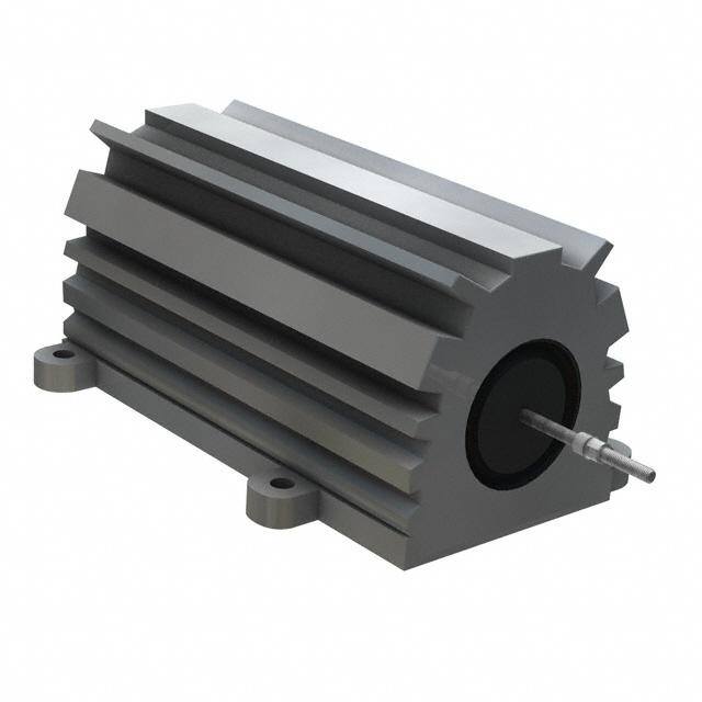
| 描述 | RES CHAS MNT 2K OHM 1% 250W线绕电阻器 - 底架安装 250watt 2Kohm 1% Non-Inductive |
| 产品分类 | |
| 品牌 | Vishay DaleVishay / Dale |
| 产品手册 | |
| 产品图片 |
|
| rohs | 否无铅 / 符合限制有害物质指令(RoHS)规范要求 |
| 产品系列 | 线绕电阻器,线绕电阻器 - 底架安装,Vishay / Dale NH2502K000FJ01NH |
| 数据手册 | |
| 产品型号 | NH2502K000FJ01NH2502K000FJ01 |
| 产品 | Power Resistors Wirewound Aluminum Housed |
| 产品种类 | 线绕电阻器 - 底架安装 |
| 其它名称 | NH250-2.00K |
| 功率(W) | 250W |
| 功率额定值 | 250 W |
| 包装 | 散装 |
| 商标 | Vishay / Dale |
| 外壳宽度 | 76.2 mm |
| 外壳直径 | 53.98 mm |
| 外壳长度 | 114.3 mm |
| 外壳高度 | 55.58 mm |
| 大小/尺寸 | 4.500" 长 x 3.000" 宽(114.30mm x 76.20mm) |
| 安装特性 | 法兰 |
| 容差 | ±1%1 % |
| 封装 | Bulk |
| 封装/外壳 | 轴向,盒 |
| 工作温度范围 | - 55 C to + 250 C |
| 工厂包装数量 | 1 |
| 引线形式 | 焊片 |
| 成分 | 绕线 |
| 标准包装 | 1 |
| 涂层,外壳类型 | 铝 |
| 温度系数 | 20 PPM / C±20ppm/°C |
| 特性 | 非电感 |
| 电阻 | 2 kOhms |
| 电阻(Ω) | 2k |
| 端接类型 | Solder Lug |
| 类型 | Wirewound Resistors, Industrial Power, Aluminum Housed, Chassis Mount |
| 系列 | NH |
| 高度 | 2.219"(56.37mm) |


PDF Datasheet 数据手册内容提取
RH, NH www.vishay.com Vishay Dale Wirewound Resistors, Industrial Power, Aluminum Housed, Chassis Mount FEATURES • Molded construction for total environmental protection • Complete welded construction Available • Meets applicable requirements of MIL-PRF-18546 • Available in non-inductive styles (type NH) with Ayrton-Perry winding for lowest reactive components • Mounts on chassis to utilize heat-sink effect • Excellent stability in operation (< 1 % change in Available resistance) DESIGN SUPPORT TOOLS click logo to get started • MIL-PRF-18546 qualified, type RE resistors can Available be found at: www.vishay.com/doc?30282 • Material categorization: Models for definitions of compliance please see Available Available www.vishay.com/doc?99912 Note * This datasheet provides information about parts that are RoHS-compliant and / or parts that are non RoHS-compliant. For example, parts with lead (Pb) terminations are not RoHS-compliant. Please see the information / tables in this datasheet for details STANDARD ELECTRICAL SPECIFICATIONS POWER RESISTANCE RESISTANCE RESISTANCE RESISTANCE WEIGHT GLOBAL HISTORICAL RATING RANGE RANGE RANGE RANGE (typical) MODEL MODEL P25 °C W ± 0.05 %, ± 0.1 % ± 0.25 % ± 0.5 % ± 1 %, ± 3 %, ± 5 % g RH005 RH-5 7.5 0.5 to 6.75K 0.1 to 8.6K 0.05 to 8.6K 0.02 to 24.5K 3 NH005 NH-5 7.5 0.5 to 2.32K 0.1 to 3.27K 0.05 to 3.27K 0.05 to 12.75K 3 RH010 RH-10 12.5 0.5 to 12.7K 0.1 to 16.69K 0.05 to 16.69K 0.01 to 47.1K 5 NH010 NH-10 12.5 0.5 to 4.45K 0.1 to 5.54K 0.05 to 5.54K 0.05 to 23.5K 5 RH025 RH-25 25 0.5 to 25.7K 0.1 to 32.99K 0.05 to 32.99K 0.01 to 95.2K 12 NH025 NH-25 25 0.5 to 9.09K 0.1 to 12.8K 0.05 to 12.8K 0.05 to 47.6K 12 RH050 RH-50 50 0.5 to 73.4K 0.1 to 96K 0.05 to 96K 0.01 to 273K 28 NH050 NH-50 50 0.5 to 26K 0.1 to 36.7K 0.05 to 36.7K 0.05 to 136K 28 RH100 RH-100 100 0.5 to 90K 0.1 to 90K 0.05 to 90K 0.05 to 90K 353 NH100 NH-100 100 0.5 to 37.5K 0.1 to 37.5K 0.05 to 37.5K 0.05 to 37.5K 353 RH250 RH-250 250 0.5 to 116K 0.1 to 116K 0.05 to 116K 0.05 to 116K 637 NH250 NH-250 250 0.5 to 48.5K 0.1 to 48.5K 0.05 to 48.5K 0.05 to 48.5K 637 Note • RH005 and NH005 printed with 5 W power rating. RH010 and NH010 printed with 10 W power rating. New construction allows these resistors to be rated at higher wattage but will only be printed with the higher wattage upon customer request TECHNICAL SPECIFICATIONS PARAMETER UNIT RH RESISTOR CHARACTERISTICS Temperature Coefficient ppm/°C ± 20 for 10 and above; ± 50 for 1 to 9.9 , ± 100 for 0.1 to 0.99 Maximum Working Voltage V (P x R)1/2 Insulation Resistance 10 000 M minimum dry, 1000 M minimum after moisture test Solderability - Meets requirements of ANSI J-STD-002 Operating Temperature Range °C -55 to +250 GLOBAL PART NUMBER INFORMATION Global Part Numbering example: RH0054R125FC02 R H 0 0 5 4 R 1 2 5 F C 0 2 GLOBAL MODEL RESISTANCE VALUE TOLERANCE CODE PACKAGING SPECIAL RH005 R = decimal A = 0.05 % E02 = lead (Pb)-free, card pack (RH005 - RH050) (see Standard K = thousand B = 0.1 % E01 = lead (Pb)-free, skin pack (RH100 and RH250) (dash number) Electrical 15R00 = 15 C = 0.25 % C02 = tin / lead, card pack (RH005 - RH050) (up to 3 digits) Specifications 10K00 = 10 k D = 0.5 % J01 = tin / lead, skin pack (RH100 and RH250) from 1 to 999 Global Model F = 1.0 % column for H = 3.0 % as applicable options) J = 5.0 % Historical Part Numbering example: RH-5 4.125 1 % C02 RH-5 4.125 1 % C02 HISTORICAL MODEL RESISTANCE VALUE TOLERANCE CODE PACKAGING Revision: 14-Nov-17 1 Document Number: 30201 For technical questions, contact: ww2aresistors@vishay.com THIS DOCUMENT IS SUBJECT TO CHANGE WITHOUT NOTICE. THE PRODUCTS DESCRIBED HEREIN AND THIS DOCUMENT ARE SUBJECT TO SPECIFIC DISCLAIMERS, SET FORTH AT www.vishay.com/doc?91000
RH, NH www.vishay.com Vishay Dale DIMENSIONS in inches [millimeters] D RH005, 010, 025, 050 C F NH005, 010, 025, 050 A M E N G J B P H L K GLOBAL DIMENSIONS in inches [millimeters] MODEL A B C D E F G H J K L M N P 0.444 0.490 0.600 1.125 0.334 0.646 0.320 0.065 0.133 0.078 0.093 0.078 0.050 0.266 RH005 ± 0.005 ± 0.005 ± 0.030 ± 0.062 ± 0.015 ± 0.015 ± 0.015 ± 0.010 ± 0.010 ± 0.010 ± 0.005 ± 0.015 ± 0.005 ± 0.062 NH005 [11.28 [12.45 [15.24 [28.58 [8.48 [16.41 [8.13 [1.65 [3.38 [1.98 [2.36 [1.98 [1.27 [6.76 ± 0.127] ± 0.127] ± 0.787] ± 1.57] ± 0.381] ± 0.381] ± 0.381] ± 0.254] ± 0.254] ± 0.254] ± 0.127] ± 0.381] ± 0.127] ± 1.57] 0.562 0.625 0.750 1.375 0.420 0.800 0.390 0.075 0.165 0.093 0.094 0.102 0.085 0.312 RH010 ± 0.005 ± 0.005 ± 0.031 ± 0.062 ± 0.015 ± 0.015 ± 0.015 ± 0.010 ± 0.010 ± 0.010 ± 0.005 ± 0.015 ± 0.005 ± 0.062 NH010 [14.27 [15.88 [19.05 [34.93 [10.67 [20.32 [9.91 [1.91 [4.19 [2.36 [2.39 [2.59 [2.16 [7.92 ± 0.127] ± 0.127] ± 0.787] ± 1.57] ± 0.381] ± 0.381] ± 0.381] ± 0.254] ± 0.254] ± 0.254] ± 0.127] ± 0.381] ± 0.127] ± 1.57] 0.719 0.781 1.062 1.938 0.550 1.080 0.546 0.075 0.231 0.172 0.125 0.115 0.085 0.438 RH025 ± 0.005 ± 0.005 ± 0.031 ± 0.062 ± 0.015 ± 0.015 ± 0.015 ± 0.010 ± 0.010 ± 0.010 ± 0.005 ± 0.015 ± 0.005 ± 0.062 NH025 [18.26 [19.84 [26.97 [49.23 [13.97 [27.43 [13.87 [1.91 [5.87 [4.37 [3.18 [2.92 [2.16 [11.13 ± 0.127] ± 0.127] ± 0.787] ± 1.57] ± 0.381] ± 0.381] ± 0.381] ± 0.254] ± 0.254] ± 0.254] ± 0.127] ± 0.381] ± 0.127] ± 1.57] 1.562 0.844 1.968 2.781 0.630 1.140 0.610 0.088 0.260 0.196 0.125 0.107 0.085 0.438 RH050 ± 0.005 ± 0.005 ± 0.031 ± 0.062 ± 0.015 ± 0.015 ± 0.015 ± 0.010 ± 0.010 ± 0.010 ± 0.005 ± 0.015 ± 0.005 ± 0.062 NH050 [39.67 [21.44 [49.99 [70.64 [16.00 [28.96 [15.49 [2.24 [6.60 [4.98 [3.18 [2.72 [2.16 [11.13 ± 0.127] ± 0.127] ± 0.787] ± 1.57] ± 0.381] ± 0.381] ± 0.381] ± 0.254] ± 0.254] ± 0.254] ± 0.127] ± 0.381] ± 0.127] ± 1.57] DIMENSIONS in inches [millimeters] RH100, NH100 0.188 ± 0.010 Stainless steel nut and stud [838.5.900 ± ± 0 0.0.73817] [4.7D8ia ±. t0y.p2.54] [14.68.1022 ±± 00..073817] 1.125 ± 0.031 [28.58 ± 0.787] 2.812 ± 0.031 [71.42 ± 0.787] 1.75 ± 0.031 2.25 ± 0.010 [44.45 ± 0.787] [57.15 ± 0.254] 0.375 ± 0.031 12 - 24 [9.52 ± 0.787] 0.989 ± 0.031 0.188 ± 0.031 0.770 ± 0.015 UNC-2A [25.12 ± 0.787] [4.78 ± 0.787] [19.56 ± 0.381] Thd. typ. 2.75 ± 0.010 typ. [69.85 ± 0.254] 5.478 ± 0.093 [139.14 ± 2.36] RH250, NH250 0.188 ± 0.010 [4.78 ± 0.254] Nickel plated Dia. typ. 1/4 - 20 2.125 ± 0.031 brass nut 4.50 ± 0.031 UNC-2A thd. typ. [53.98 ± 0.787] stainless steel stud [114.30 ± 0.787] 1.25 ± 0.062 [31.75 ± 1.575] 3.0 ± 0.031 2.188 ± 0.031 [76.20 ± 0.787] [55.58 ± 0.787] 2.50 ± 0.010 [63.50 ± 0.254] 0.312 ± 0.031 0[2.28.7253 ±± 00..205140] [311.2.755 ± ± 0 1.0.56725] [06..23550 ± ± 0 0.7.08371] [02.49.5256 ±± 00..301851] [7.92 ± 0.787] 3.0 ± 0.010 typ. [76.20 ± 0.254] 3.875 ± 0.010 [98.42 ± 0.254] 7.0 ± 0.093 [177.80 ± 2.36] Revision: 14-Nov-17 2 Document Number: 30201 For technical questions, contact: ww2aresistors@vishay.com THIS DOCUMENT IS SUBJECT TO CHANGE WITHOUT NOTICE. THE PRODUCTS DESCRIBED HEREIN AND THIS DOCUMENT ARE SUBJECT TO SPECIFIC DISCLAIMERS, SET FORTH AT www.vishay.com/doc?91000
RH, NH www.vishay.com Vishay Dale POWER RATING Vishay RH resistor wattage ratings are based on mounting to the following heat sink: RH005 and RH010: 4" x 6" x 2" x 0.040" thick aluminum chassis (129 sq. in. surface area) RH025: 5" x 7" x 2" x 0.040" thick aluminum chassis (167 sq. in. surface area) RH050: 12" x 12" x 0.059" thick aluminum panel (291 sq. in. surface area) RH100 and RH250: 12" x 12" x 0.125" thick aluminum panel (294 sq. in. surface area) FREE AIR POWER RATING GLOBAL RH005 RH010 RH025 RH050 RH100 RH250 MODEL NH005 NH010 NH025 NH050 NH100 NH250 W at 25 °C 4.5 7.5 12.5 20 40 100 AMBIENT TEMPERATURE DERATING Derating is required for ambient temperatures above 25 °C, see the following graph. Curves A, B, C apply to operation of unmounted resistors. Curve D applies to all types when mounted to specified heat sink. A = RH005 and RH010 size resistor, unmounted B = RH025 size resistor, unmounted C = RH050, RH100 and RH250 size resistor, unmounted D = All types mounted to recommended aluminum heat sink 120 % N R I 100 E W O P 80 D E D T A A 60 R B C 40 20 0 - 55- 50 0 50 150 250 25 AMBIENT TEMPERATURE IN °C REDUCED HEAT SINK DERATING Derating is also required when recommended heat sink area is reduced. A = RH005 and RH010 size resistor B = RH025 size resistor C = RH050, RH100 and RH250 size resistor 100 % N 90 R I E 80 W O 70 A P D 60 ATE 50 B R C 40 30 20 10 0 0 20 40 60 80 100 % OF RECOMMENDED HEAT SINK AREA Revision: 14-Nov-17 3 Document Number: 30201 For technical questions, contact: ww2aresistors@vishay.com THIS DOCUMENT IS SUBJECT TO CHANGE WITHOUT NOTICE. THE PRODUCTS DESCRIBED HEREIN AND THIS DOCUMENT ARE SUBJECT TO SPECIFIC DISCLAIMERS, SET FORTH AT www.vishay.com/doc?91000
RH, NH www.vishay.com Vishay Dale MATERIAL SPECIFICATIONS SPECIAL MODIFICATIONS Element: copper-nickel alloy or nickel-chrome alloy, A number of special modifications to the aluminum housed depending on resistance value resistor style are available upon request. Special Core: ceramic, steatite or alumina, depending on physical modifications include: size • Terminal configurations and materials Encapsulant: silicone molded construction • Resistance values and tolerances Housing: aluminum with hard anodic coating • Low resistance temperature coefficient (RTC) End Caps: stainless steel • Housing configuration Standard Terminals: For RH005 through RH050 size • Threaded mounting holes terminal finish - tin / lead is 60/40 Sn/Pb w/Nickel underplate • Preconditioning and other additional testing and lead (Pb)-free is Ni/Pd/Au, finish is on copper clad steel core terminal. For RH100 and RH250 terminals are threaded APPLICABLE MIL SPECIFICATIONS stainless steel. Vishay RH and NH resistors are listed as qualified on the Part Marking: Dale, model, wattage, value, tolerance, date MIL-PRF-18546 QPL. MIL-PRF-18546 qualified, type RE code resistors can be found at: www.vishay.com/doc?30282 NH NON-INDUCTIVE Models of equivalent physical and electrical specifications are available with non-inductive (Ayrton-Perry) winding. They are identified by substituting the letter N for R in the model number (NH005, for example). PERFORMANCE TEST CONDITIONS OF TEST TEST LIMITS Thermal Shock Rated power applied until thermally stable, then a minimum of 15 min at -55 °C ± (0.5 % + 0.05 ) R Short Time Overload 5x rated power for 5 s ± (0.5 % + 0.05 ) R Dielectric Withstanding 1000 VRMS for RH005, RH010 and RH025; 2000 VRMS for RH050; ± (0.2 % + 0.05 ) R Voltage 4500 VRMS for RH100 and RH250; duration 1 min Temperature 250 °C for 2 h ± (0.5 % + 0.05 ) R Moisture Resistance MIL-STD-202 Method 106, 7b not applicable ± (1.0 % + 0.05 ) R Shock, Specified Pulse MIL-STD-202 Method 213, 100 g’s for 6 ms, 10 shocks ± (0.2 % + 0.05 ) R Vibration, High Frequency Frequency varied 10 Hz to 2000 Hz, 20 g peak, 2 directions 6 h each ± (0.2 % + 0.05 ) R Load Life 1000 h at rated power, +25 °C, 1.5 h “ON”, 0.5 h “OFF” ± (1.0 % + 0.05 ) R 30 s, 5 pound pull test for RH005 and RH010, 10 pound pull test for other sizes; Terminal Strength ± (0.2 % + 0.05 ) R torque test - 24 pound inch for RH100 and 32 pound inch for RH250 Revision: 14-Nov-17 4 Document Number: 30201 For technical questions, contact: ww2aresistors@vishay.com THIS DOCUMENT IS SUBJECT TO CHANGE WITHOUT NOTICE. THE PRODUCTS DESCRIBED HEREIN AND THIS DOCUMENT ARE SUBJECT TO SPECIFIC DISCLAIMERS, SET FORTH AT www.vishay.com/doc?91000
Legal Disclaimer Notice www.vishay.com Vishay Disclaimer ALL PRODUCT, PRODUCT SPECIFICATIONS AND DATA ARE SUBJECT TO CHANGE WITHOUT NOTICE TO IMPROV E RELIABILITY, FUNCTION OR DESIGN OR OTHERWISE. Vishay Intertechnology, Inc., its affiliates, agents, and employees, and all persons acting on its or their behalf (collectively, “Vishay”), disclaim any and all liability for any errors, inaccuracies or incompleteness contained in any datasheet or in any other disclosure relating to any product. Vishay makes no warranty, representation or guarantee regarding the suitability of the products for any particular purpose o r the continuing production of any product. To the maximum extent permitted by applicable law, Vishay disclaims (i) any and all liability arising out of the application or use of any product, (ii) any and all liability, including without limitation special, consequential or incidental damages, and (iii) any and all implied warranties, including warranties of fitness for particular purpose, non-infringement and merchantability. Statements regarding the suitability of products for certain types of applications are based on Vishay’s knowledge of typical requirements that are often placed on Vishay products in generic applications. Such statements are not binding statements about the suitability of products for a particular application. It is the customer’s responsibility to validate that a particular product with the properties described in the product specification is suitable for use in a particular application. Parameters provided in datasheets and / or specifications may vary in different applications and performance may vary over time. All operating parameters, including typical parameters, must be validated for each customer application by the customer’s technical experts. Product specifications do not expand or otherwise modify Vishay’s terms and conditions of purchase, including but not limited to the warranty expressed therein. Except as expressly indicated in writing, Vishay products are not designed for use in medical, life-saving, or life-sustainin g applications or for any other application in which the failure of the Vishay product could result in personal injury or death. Customers using or selling Vishay products not expressly indicated for use in such applications do so at their own risk . Please contact authorized Vishay personnel to obtain written terms and conditions regarding products designed for such applications. No license, express or implied, by estoppel or otherwise, to any intellectual property rights is granted by this documen t or by any conduct of Vishay. Product names and markings noted herein may be trademarks of their respective owners. © 2019 VISHAY INTERTECHNOLOGY, INC. ALL RIGHTS RESERVED Revision: 01-Jan-2019 1 Document Number: 91000