ICGOO在线商城 > 集成电路(IC) > PMIC - 稳压器 - 线性 > NCV8570BSN28T1G
 Datasheet下载
- 型号: NCV8570BSN28T1G
- 制造商: ON Semiconductor
- 库位|库存: xxxx|xxxx
- 要求:
| 数量阶梯 | 香港交货 | 国内含税 |
| +xxxx | $xxxx | ¥xxxx |
查看当月历史价格
查看今年历史价格
NCV8570BSN28T1G产品简介:
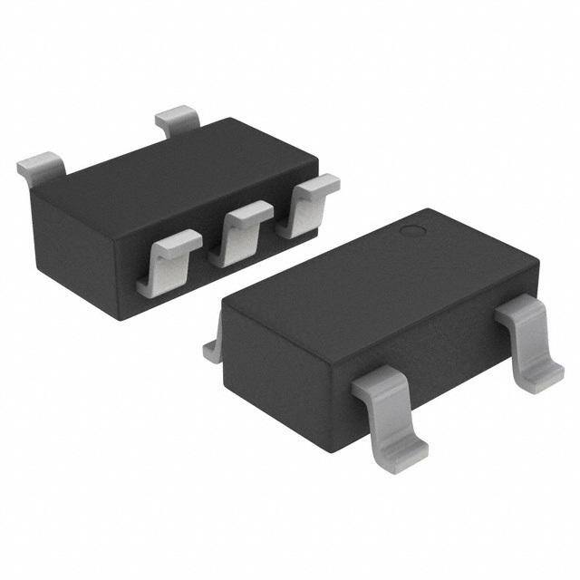
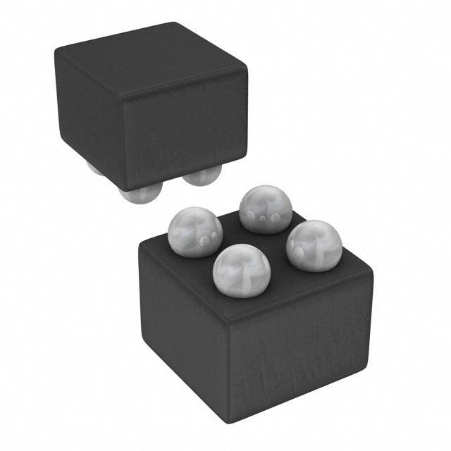
ICGOO电子元器件商城为您提供NCV8570BSN28T1G由ON Semiconductor设计生产,在icgoo商城现货销售,并且可以通过原厂、代理商等渠道进行代购。 NCV8570BSN28T1G价格参考。ON SemiconductorNCV8570BSN28T1G封装/规格:PMIC - 稳压器 - 线性, Linear Voltage Regulator IC 正,固定式 1 Output 200mA 5-TSOP。您可以下载NCV8570BSN28T1G参考资料、Datasheet数据手册功能说明书,资料中有NCV8570BSN28T1G 详细功能的应用电路图电压和使用方法及教程。
ON Semiconductor(安森美)的NCV8570BSN28T1G是一款专为汽车应用设计的低压差线性稳压器(LDO),属于PMIC - 稳压器 - 线性产品类别。该器件可提供稳定的2.8V输出电压,额定输出电流可达150mA,具备低静态电流和高电源抑制比(PSRR),适用于对电源噪声敏感的系统。

NCV8570BSN28T1G主要应用于汽车电子系统,如车身控制模块、仪表盘、信息娱乐系统、远程信息处理单元和高级驾驶辅助系统(ADAS)等。其宽输入电压范围(可达45V)和内置过压、过热及短路保护功能,使其能够在恶劣的汽车电气环境中稳定运行。此外,该器件符合AEC-Q100汽车级认证标准,确保在高温、振动和电压波动等严苛条件下的可靠性。

由于采用小型SOT-23封装,NCV8570BSN28T1G节省电路板空间,适合空间受限的车载应用。其低功耗特性也支持汽车在待机或熄火模式下降低整体能耗,满足节能与环保需求。

综上,NCV8570BSN28T1G广泛用于需要高可靠性、小尺寸和低噪声电源的汽车电子模块,是汽车行业中理想的线性稳压解决方案之一。
| 参数 | 数值 |
| 产品目录 | 集成电路 (IC)半导体 |
| 描述 | IC REG LDO 2.8V 0.2A 5TSOP低压差稳压器 200MA ULN RF LDO REG2.8V |
| 产品分类 | |
| 品牌 | ON Semiconductor |
| 产品手册 | |
| 产品图片 |
|
| rohs | 符合RoHS无铅 / 符合限制有害物质指令(RoHS)规范要求 |
| 产品系列 | 电源管理 IC,低压差稳压器,ON Semiconductor NCV8570BSN28T1G- |
| 数据手册 | |
| 产品型号 | NCV8570BSN28T1G |
| 产品种类 | 低压差稳压器 |
| 供应商器件封装 | 5-TSOP |
| 其它名称 | NCV8570BSN28T1GOSCT |
| 包装 | 剪切带 (CT) |
| 商标 | ON Semiconductor |
| 回动电压—最大值 | 90 mV |
| 安装类型 | 表面贴装 |
| 安装风格 | SMD/SMT |
| 封装 | Reel |
| 封装/外壳 | 6-TSOP(0.059",1.50mm 宽)5 引线 |
| 封装/箱体 | TSOP-5 |
| 工作温度 | -40°C ~ 125°C |
| 工厂包装数量 | 3000 |
| 最大工作温度 | + 85 C |
| 最大输入电压 | 6 V |
| 标准包装 | 1 |
| 电压-跌落(典型值) | 0.12V @ 200mA |
| 电压-输入 | 最高 5.5V |
| 电压-输出 | 2.8V |
| 电流-输出 | 200mA |
| 电流-限制(最小值) | 200mA |
| 稳压器拓扑 | 正,固定式 |
| 稳压器数 | 1 |
| 系列 | NCV8570B |
| 负载调节 | 0.2 mV |
| 输出电压 | 2.8 V |
| 输出电流 | 150 mA |


- 商务部:美国ITC正式对集成电路等产品启动337调查
- 曝三星4nm工艺存在良率问题 高通将骁龙8 Gen1或转产台积电
- 太阳诱电将投资9.5亿元在常州建新厂生产MLCC 预计2023年完工
- 英特尔发布欧洲新工厂建设计划 深化IDM 2.0 战略
- 台积电先进制程称霸业界 有大客户加持明年业绩稳了
- 达到5530亿美元!SIA预计今年全球半导体销售额将创下新高
- 英特尔拟将自动驾驶子公司Mobileye上市 估值或超500亿美元
- 三星加码芯片和SET,合并消费电子和移动部门,撤换高东真等 CEO
- 三星电子宣布重大人事变动 还合并消费电子和移动部门
- 海关总署:前11个月进口集成电路产品价值2.52万亿元 增长14.8%


PDF Datasheet 数据手册内容提取
NCV8570B Linear Voltage Regulator - LDO, Ultra Low Noise, High PSRR 200 mA The NCV8570B is a 200 mA Low Dropout, Linear Voltage http://onsemi.com Regulator with ultra low noise characteristics. It’s low noise combined with high Power Supply Rejection Ratio (PSRR) make it especially suited for use in RF, audio or imaging applications. The device is manufactured in an advanced BiCMOS process to provide a powerful combination of low noise and excellent dynamic performance but with DFN6 TSOP−5 MN SUFFIX SN SUFFIX very low ground current consumption at full loads. CASE 506BA CASE 483 The NCV8570B is stable with small, low value capacitors allowing designers to minimise the total PCB space occupied by the solution. PIN CONNECTIONS The device is packaged in a small 2x2.2mm DFN6 package as well as in a TSOP-5 package. EN 1 6 BYP Features • Ultra Low Noise (typ. 10 (cid:2)Vrms @ V = 1.8 V) GND 2 5 GND OUT • Very High PSRR (typ. 82 dB @ 1 kHz) IN 3 4 OUT • Excellent Line and Load Regulation DFN6 • Stable with Ceramic Output Capacitors as low as 1 (cid:2)F (Top View) • Very Low Ground Current (typ. 75 (cid:2)A @ IOUT = 200 mA) 1 5 • Low Sleep Mode Current (max. 1 (cid:2)A) IN OUT • Active Discharge Circuit GND • Current Limit and Thermal Shutdown Protection EN BYP • Output Voltage Options: TSOP−5 ♦ 1.8 V, 2.5 V, 2.8 V, 3.0 V, 3.3 V (Top View) ♦ Contact Factory for Other Voltage Options • MARKING DIAGRAMS NCV Prefix for Automotive and Other Applications Requiring Unique Site and Control Change Requirements; AEC−Q100 1 Qualified and PPAP Capable XX M(cid:2) • (cid:2) These are Pb−Free Devices Applications XX = Specific Device Code • Satellite and HD Radio M = Date Code • Portable/Built−in DVD Entertainment Systems (cid:2) = Pb−Free Package* • (*Note: Microdot may be in either location) Noise Sensitive Applications (RF, Video, Audio) • GPS Systems 5 • Camera for Lane Change Detection and Reverse View XXXAYW(cid:2) (cid:2) DFN6 2x2.2 1 VIN 3 4 VOUT XXX= Specific Device Code IN OUT A = Assembly Location NCV8570B 1 6 Y = Year EN BYP 1C (cid:2)IFN OFF ON GND2, 5, EPAD C10n onisFe C1 O(cid:2)FUT W(cid:2) == PWbo−rFk rWeee ePkackage* (*Note: Microdot may be in either location) ORDERING INFORMATION Figure 1. NCV8570B Typical Application Schematic See detailed ordering, marking and shipping information in the package dimensions section on page 18 of this data sheet. © Semiconductor Components Industries, LLC, 2013 1 Publication Order Number: October, 2019 − Rev. 3 NCV8570B/D
NCV8570B RDIS RPD Figure 2. Simplified Block Diagram PIN FUNCTION DESCRIPTION Pin No. Pin No. DFN6 TSOP−5 Pin Name Description 1 3 EN Enable pin: This pin allows on/off control of the regulator. To disable the device, connect to GND. If this function is not in use, connect to Vin. Internal 5 M(cid:3) Pull Down resistor is connected between EN and GND. 2, 5, EPAD 2 GND Power Supply Ground (Pins are fused for the DFN6 package). Pins 2, 5 and EPAD are connected together through the lead frame in the DFN6 package. 3 1 IN Power Supply Input Voltage 4 5 OUT Regulated Output Voltage 6 4 BYP Noise reduction pin. (Connect 10 nF or 100 nF capacitor to GND) MAXIMUM RATINGS Rating Symbol Value Unit Input Voltage (Note 2) IN −0.3 V to 6 V V Chip Enable Voltage EN −0.3 V to VIN +0.3 V Noise Reduction Voltage BYP −0.3 V to VIN +0.3 V V Output Voltage OUT −0.3 V to VIN +0.3 V V Output Short−Circuit Duration Infinity Maximum Junction Temperature TJ(max) 125 °C Storage Temperature Range TSTG −55 to 150 °C Stresses exceeding Maximum Ratings may damage the device. Maximum Ratings are stress ratings only. Functional operation above the Recommended Operating Conditions is not implied. Extended exposure to stresses above the Recommended Operating Conditions may affect device reliability. 1. This device series contains ESD protection and exceeds the following tests: Human Body Model 2000 V tested per MIL−STD−883, Method 3015 Machine Model Method 200 V This device meets or exceeds AEC−Q100 standard. THERMAL CHARACTERISTICS Rating Symbol Value Unit Package Thermal Resistance, DFN6: (Notes 2, 3) °C/W Junction−to−Case (Pin 2) (cid:4)JL2 38 Junction−to−Ambient R(cid:5)JA 110 Package Thermal Resistance, TSOP−5: (Notes 2, 3) °C/W Junction−to−Case (Pin 2) (cid:4)JL2 92 Junction−to−Ambient R(cid:5)JA 204 2. Refer to APPLICATION INFORMATION for Safe Operating Area 3. Single component mounted on 1 oz, FR4 PCB with 645mm2 Cu area. http://onsemi.com 2
NCV8570B ELECTRICAL CHARACTERISTICS (VIN = VOUT + 0.5 V or 2.5 V (whichever is greater), VEN = 1.2 V, CIN = COUT = 1 (cid:2)F, Cnoise = 10 nF, IOUT = 1 mA, TJ = −40°C to 125°C, unless otherwise specified) (Note 4) Parameter Test Conditions Symbol Min Typ Max Unit REGULATOR OUTPUT Input Voltage Range VIN 2.5 − 5.5 V Output Voltage 1.8 V VIN = (VOUT + 0.5 V) to 5.5 V VOUT 1.755 − 1.845 V 2.5 V IOUT = 1 mA to 200 mA 2.4375 − 2.5625 2.8 V 2.730 − 2.870 3.0 V 2.925 − 3.075 3.3 V 3.2175 − 3.3825 (−2.5%) (+2.5%) Power Supply Ripple Rejection VIN = VOUT +1.0 V, f = 120 Hz PSRR − 80 − dB IOUT = 1 mA to 150 mA f = 1 kHz − 82 − f = 10 kHz − 63 − Line Regulation VIN = (VOUT +0.5 V) to 5.5 V, IOUT = 1 mA (cid:6)VOUT / (cid:6)VIN −0.1 − 0.1 %/V Load Regulation IOUT = 1 mA to 200 mA (cid:6)VOUT / (cid:6)IOUT − 0.2 5.0 mV Output Noise Voltage VOUT = 1.8 V, Cnoise = 100 nF VN − 10 − (cid:2)VRMS f = 10 Hz to 100 kHz, Cnoise = 10 nF − 15 − IOUT = 1 mA to 150 mA Output Current Limit VOUT = VOUT(NOM) – 0.1 V ILIM 200 310 470 mA Output Short Circuit Current VOUT = 0V ISC 205 320 490 mA Dropout Voltage (Note 5) IOUT= 150 mA VOUT(NOM) = 2.5 V VDO − 100 180 mV VOUT(NOM) = 2.8 V − 90 165 VOUT(NOM) = 3.0 V − 85 150 VOUT(NOM) = 3.3 V − 80 145 Dropout Voltage (Note 5) IOUT= 200 mA VOUT(NOM) = 2.5 V VDO − 140 230 mV VOUT(NOM) = 2.8 V − 120 205 VOUT(NOM) = 3.0 V − 115 190 VOUT(NOM) = 3.3 V − 110 185 GENERAL Ground Current IOUT = 1 mA IGND − 70 110 (cid:2)A IOUT = 200 mA − 75 130 Disable Current VEN = 0 V IDIS − 0.1 1.0 (cid:2)A Thermal Shutdown Shutdown, Temperature Increasing TSDU − 150 − °C Reset, Temperature Decreasing TSDD − 135 − °C OUTPUT ENABLE Enable Threshold Low Vth(EN) − − 0.4 V High 1.2 − − Internal Pull−Down Resistance RPD(EN) 2.5 5.0 10 M(cid:3) (Note 6) TIMING Turn−On Time IOUT = 10 mA, VOUT = Cnoise = 10 nF tON − 0.4 − ms 0.975 VOUT(NOM) Cnoise = 100 nF − 4.0 − Turn−Off Time Cnoise = 10nF/100nF, IOUT = 1 mA tOFF − 2.0 − ms VOUT = 0.1 VOUT(NOM) IOUT = 10 mA − 0.6 − 4. Performance guaranteed over the indicated operating temperature range by design and/or characterization tested at TJ = TA = 25°C. Low duty cycle pulse techniques are used during testing to maintain the junction temperature as close to ambient as possible. 5. Measured when the output voltage falls 100 mV below the nominal output voltage (nominal output voltage is the voltage at the output meas- ured under the condition VIN = VOUT + 0.5 V). In the case of devices having the nominal output voltage VOUT = 1.8 V the minimum input to output voltage differential is given by the VIN(MIN) = 2.5 V. 6. Expected to disable the device when EN pin is floating. http://onsemi.com 3
NCV8570B TYPICAL CHARACTERISTICS 1.836 V) 1.824 E ( G A 1.812 T L O T V 1.800 U P T U 1.788 O , ut VIN = 2.5 V, Vo 1.776 CIN = COUT = 1 (cid:2)F, Cnoise = 10 nF 1.764 −40 −20 0 20 40 60 80 100 120 TJ, JUNCTION TEMPERATURE (°C) Figure 3. Output Voltage vs. Junction Temperature, V = 1.8 V OUT 2.8560 V) 2.8373 E ( G A 2.8187 T L O T V 2.8000 U P T U 2.7813 O , ut Vo 2.7627 VIN = 3.3 V, CIN = COUT = 1 (cid:2)F, 2.7440 Cnoise = 10 nF −40 −20 0 20 40 60 80 100 120 TJ, JUNCTION TEMPERATURE (°C) Figure 4. Output Voltage vs. Junction Temperature, V = 2.8 V OUT 3.06 V) 3.04 E ( G A 3.02 T L O T V 3.00 U P T U 2.98 O , ut Vo 2.96 VIN = 3.5 V, CIN = COUT = 1 (cid:2)F, 2.94 Cnoise = 10 nF −40 −20 0 20 40 60 80 100 120 TJ, JUNCTION TEMPERATURE (°C) Figure 5. Output Voltage vs. Junction Temperature, V = 3.0 V OUT http://onsemi.com 4
NCV8570B TYPICAL CHARACTERISTICS 3.3660 180 CIN = COUT = 1 (cid:2)F, V) 3.3440 mV) 150 Cnoise = 10 nF AGE ( 3.3220 AGE ( 120 TJ = 25°C T T L L O O T V 3.3000 T V 90 TJ = 125°C U U P O T P U 3.2780 O 60 V, Oout 3.2560 VCCIInNNo i==se 3C =.O8 1 UV0T, n=F 1 (cid:2)F, V, DRDO 30 TJ = −40°C 3.2340 0 −40 −20 0 20 40 60 80 100 120 0 40 80 120 160 200 TJ, JUNCTION TEMPERATURE (°C) IOUT, OUTPUT CURRENT (mA) Figure 6. Output Voltage vs. Junction Figure 7. Dropout Voltage vs. Output Current, Temperature, V = 3.3 V V = 2.8 V OUT OUT 180 180 CIN = COUT = 1 (cid:2)F, CIN = COUT = 1 (cid:2)F, V) Cnoise = 10 nF V) Cnoise = 10 nF m 150 m 150 E ( E ( G G A 120 A 120 OLT TJ = 25°C OLT TJ = 25°C V V T 90 T 90 OU TJ = 125°C OU TJ = 125°C P P O 60 O 60 R R , DO 30 TJ = −40°C , DO 30 TJ = −40°C D D V V 0 0 0 40 80 120 160 200 0 40 80 120 160 200 IOUT, OUTPUT CURRENT (mA) IOUT, OUTPUT CURRENT (mA) Figure 8. Dropout Voltage vs. Output Current, Figure 9. Dropout Voltage vs. Output Current, V = 3.0 V V = 3.3 V OUT OUT http://onsemi.com 5
NCV8570B TYPICAL CHARACTERISTICS 100 110 90 IOUT = 10 mA 100 IOUT = 10 mA 80 90 80 70 IOUT = 150 mA 70 IOUT = 150 mA B) 60 B) d d 60 RR ( 50 IOUT = 200 mA RR ( 50 IOUT = 200 mA S 40 S P 30 TA = 25°C, P 40 TA = 25°C, 20 CCnOoUisTe == 11 0(cid:2) Fn,F, 2300 CCnOoUisTe == 11 0(cid:2)0F, nF, 100 VVOINU =T 3=. 01 .V8 DVC, ± 50 mVAC 100 VVOINU =T 3=. 01 .V8 DVC, ± 50 mVAC 10 100 1k 10k 100k 1M 10 100 1k 10k 100k 1M FREQUENCY (Hz) FREQUENCY (Hz) Figure 10. PSRR vs. Frequency, 1.8 V Output Figure 11. PSRR vs. Frequency, 1.8 V Output Voltage Option, C = 1 (cid:2)F, C = 10 nF Voltage Option, C = 1(cid:2)F, C = 100nF OUT noise OUT noise 100 120 90 IOUT = 10 mA 110 IOUT = 10 mA 100 80 90 70 80 B) 60 IOUT = 150 mA B) 70 IOUT = 150 mA R (d 50 IOUT = 200 mA R (d 60 SR 40 SR 50 IOUT = 200 mA P 30 TA = 25°C, P 40 TA = 25°C, 20 CCnOoUisTe == 41.07 n(cid:2)FF,, 2300 CCnOoUisTe == 41.070 (cid:2) nF,F, 100 VVOINU =T 3=. 01 .V8 DVC, ± 50 mVAC 100 VVOINU =T 3=. 01 .V8 DVC, ± 50 mVAC 10 100 1k 10k 100k 1M 10 100 1k 10k 100k 1M FREQUENCY (Hz) FREQUENCY (Hz) Figure 12. PSRR vs. Frequency, 1.8 V Output Figure 13. PSRR vs. Frequency, 1.8V Output Voltage Option, C = 4.7 (cid:2)F, C = 10 nF Voltage Option, C = 4.7(cid:2)F, C = 100nF OUT noise OUT noise 110 110 100 100 IOUT = 10 mA IOUT = 10 mA 90 90 IOUT = 150 mA 80 IOUT = 150 mA 80 70 70 dB) 60 dB) 60 IOUT = 200 mA RR ( 50 IOUT = 200 mA RR ( 50 S S P 40 TA = 25°C, P 40 TA = 25°C, 30 Cnoise = 10 nF, 30 Cnoise = 100 nF, 20 COUT = 1 (cid:2)F, 20 COUT = 1 (cid:2)F, 10 VVOINU =T 3=. 32 .V8 DVC, ± 50 mVAC 10 VVOINU =T 3=. 32 .V8 DVC, ± 50 mVAC 0 0 10 100 1k 10k 100k 1M 10 100 1k 10k 100k 1M FREQUENCY (Hz) FREQUENCY (Hz) Figure 14. PSRR vs. Frequency, 2.8 V Output Figure 15. PSRR vs. Frequency, 2.8 V Output Voltage Option, C = 1 (cid:2)F, C = 10 nF Voltage Option, C = 1 (cid:2)F, C = 100 nF OUT noise OUT noise http://onsemi.com 6
NCV8570B TYPICAL CHARACTERISTICS 110 110 100 100 IOUT = 10 mA IOUT = 10 mA 90 90 80 80 70 IOUT = 150 mA 70 IOUT = 150 mA B) B) d 60 d 60 RR ( 50 IOUT = 200 mA RR ( 50 IOUT = 200 mA S S P 40 TA = 25°C, P 40 TA = 25°C, 30 Cnoise = 10 nF, 30 Cnoise = 100 nF, 20 COUT = 4.7 (cid:2)F, 20 COUT = 4.7 (cid:2)F, 10 VOUT = 2.8 V, 10 VOUT = 2.8 V, VIN = 3.3 VDC ± 50 mVAC VIN = 3.3 VDC ± 50 mVAC 0 0 10 100 1k 10k 100k 1M 10 100 1k 10k 100k 1M FREQUENCY (Hz) FREQUENCY (Hz) Figure 16. PSRR vs. Frequency, 2.8 V Output Figure 17. PSRR vs. Frequency, 2.8 V Output Voltage Option, C = 4.7 (cid:2)F, C = 10 nF Voltage Option, C = 4.7 (cid:2)F, C = 100 nF OUT noise OUT noise 10 10 HZ) 10 HzV −O 1U0T0 = k 3H.z3 IVntegral HZ) 10 HzV −O 1U0T0 = k 3H.z3 IVntegral ICOOUUTT = = 5 10 (cid:2)mFA,, √V/ Noise: Vn = 25.3 (cid:2)Vrms √V/ Noise: Vn = 11.9 (cid:2)Vrms Cnoise = 100 nF (cid:2)SE ( 1.0 10 HzV −O 1U0T0 = k 2H.z8 IVntegral (cid:2)SE ( 1.0 2V.I5N V=, VwOhUicTh =e v+e0r. 5is Vh iogrher NOI Noise: Vn = 22.6 (cid:2)Vrms NOI VOUT = 2.8 V E E 10 Hz − 100 kHz Integral TAG 10 HzV −O 1U0T0 = k 1H.z8 IVntegral TAG Noise: Vn = 11.7 (cid:2)Vrms OL 0.10 IOUT = 50 mA, Noise: Vn = 14.9 (cid:2)Vrms OL 0.10 T V COUT = 1 (cid:2)F, T V PU Cnoise = 10 nF PU VOUT = 1.8 V UT VIN = VOUT = +0.5 V or UT 10 Hz − 100 kHz Integral O 2.5 V, whichever is higher O Noise: Vn = 9.4 (cid:2)Vrms 0.01 0.01 10 100 1k 10k 100k 1M 10 100 1k 10k 100k 1M FREQUENCY (Hz) FREQUENCY (Hz) Figure 18. Output Noise vs. Frequency, C = Figure 19. Output Noise vs. Frequency, C = OUT OUT 1 (cid:2)F, C = 10 nF, I = 50 mA 1 (cid:2)F, C = 100 nF, I = 50 mA noise OUT noise OUT 10 10 √V/HZ) 1N0o HiszeV :− OV 1Un0 T=0 = 2k 23H..z83 5 IVn (cid:2)teVgrmrasl √V/HZ) 10N HozisV e−O: 1UV0Tn0 == k 3H1.2z3 (cid:2)IVnVtermgsral ICCOOnUoUTisT e= = =2 101 00(cid:2) 0Fm, nAF, (cid:2)E ( VOUT = 2.8 V (cid:2)E ( VIN = VOUT = +0.5 V or S 1.0 10 Hz − 100 kHz Integral S 1.0 2.5 V, whichever is higher NOI Noise: Vn = 22.7 (cid:2)Vrms NOI E E VOUT = 2.8 V G VOUT = 1.8 V G 10 Hz − 100 kHz Integral VOLTA 0.10 IOUT = 200 mA, 10N Hozis e−: 1V0n0 = k H15z (cid:2)InVtermgsral VOLTA 0.10 Noise: Vn = 11.7 (cid:2)Vrms T COUT = 1 (cid:2)F, T U U P Cnoise = 10 nF P VOUT = 1.8 V UT VIN = VOUT = +0.5 V or UT 10 Hz − 100 kHz Integral O 0.01 2.5 V, whichever is higher O 0.01 Noise: Vn = 9.5 (cid:2)Vrms 10 100 1k 10k 100k 1M 10 100 1k 10k 100k 1M FREQUENCY (Hz) FREQUENCY (Hz) Figure 20. Output Noise vs. Frequency, C = Figure 21. Output Noise vs. Frequency, C = OUT OUT 1 (cid:2)F, C = 10 nF, I = 200 mA 1 (cid:2)F, C = 100 nF, I = 200 mA noise OUT noise OUT http://onsemi.com 7
NCV8570B TYPICAL CHARACTERISTICS 35 20 TA = 25°C, PUT 30 CVOOUUTT == 31. 3(cid:2) FV,, PUT 1168 T T U IOUT = 200 mA U S O)s25 VIN = 3.8 V S O)s14 M m M m12 RVr RVr Hz (cid:2)E ( 20 Hz (cid:2)E ( 10 kS kS HZ to 100 NOI 15 HZ to 100 NOI 468 TCVAOn oU=isT 2e = 5= °3 C1.30, 0V n,F, 10 10 10 2 IOUT = 200 mA VIN = 3.8 V 5 0 0 50 100 150 200 250 300 350 400 450 500 1 3 5 7 9 11 13 15 17 19 21 Cnoise, NOISE BYPASS CAPACITOR (nF) COUT, OUTPUT CAPACITOR ((cid:2)F) Figure 22. Output Noise vs. Noise Bypass Figure 23. Output Noise vs. Output Capacitance, C = 1 (cid:2)F, V = 3.3 V, I = Capacitance, C = 100 nF, V = 3.3 V, OUT OUT OUT noise OUT 200 mA I = 200 mA OUT 30 15 T 28 T 14 U U P 26 VOUT = 3.3 V P 13 T T RMS OUV)rms2224 VOUT = 2.8 V RMS OUV)rms1112 VVOOUUTT == 32..38 VV Hz (cid:2)E ( 20 Hz (cid:2)E ( 10 kS kS 00 OI 18 00 OI 9 VOUT = 1.8 V 1N 1N Z to 16 VOUT = 1.8 V Z to 8 H 14 H 7 0 TA = 25°C, Cnoise = 10 nF, COUT = 1 (cid:2)F, 0 TA = 25°C, Cnoise = 100 nF, COUT = 1 (cid:2)F, 1 12 VIN = VOUT + 0.5 V or 2.5 V, whichever is higher 1 6 VIN = VOUT + 0.5 V or 2.5 V, whichever is higher 10 5 0 25 50 75 100 125 150 175 200 0 25 50 75 100 125 150 175 200 IOUT, OUTPUT CURRENT (mA) IOUT, OUTPUT CURRENT (mA) Figure 24. Output Noise vs. Load Current, Figure 25. Output Noise vs. Load Current, C = 10 nF, C = 1 (cid:2)F C = 100 nF, C = 1 (cid:2)F noise OUT noise OUT 300 200 GE (V) 200 mA 1 mA 0100 NT (mA) TA E L R O R V U T 1.85 C U T P 1.80 U T P U T O 1.75 U V, OUT 1.70 COUT = 4.7 (cid:2)F, VIN = 2.5 V, Cnoise = 100 nF, , OOUT 1.65 dIOUT/dt = 200 mA / 1 (cid:2)s I 1.60 0 40 80 120 160 200 240 280 320 360 400 t, TIME ((cid:2)s) Figure 26. Load Transient Response, V = OUT 1.8 V, C = 4.7 (cid:2)F, C = 100 nF OUT noise http://onsemi.com 8
NCV8570B TYPICAL CHARACTERISTICS 300 200 TAGE (V) 200 mA 1 mA 0100 ENT (mA) L1.90 R O R V U T 1.85 C U T P1.80 U T P U T O1.75 U V, OUT1.70 COUT = 1 (cid:2)F, VIN = 2.5 V, Cnoise = 100 nF, , OOUT 1.65 dIOUT/dt = 200 mA / 1 (cid:2)s I 1.60 0 40 80 120 160 200 240 280 320 360 400 t, TIME ((cid:2)s) Figure 27. Load Transient Response, V = OUT 1.8 V, C = 1 (cid:2)F, C = 100 nF OUT noise 300 200 GE (V) 200 mA 1 mA 0100 NT (mA) TA E L3.40 R O R V U T 3.35 C U T P3.30 U T P U T O3.25 U V, OUT3.20 COUT = 4.7 (cid:2)F, VIN = 3.8 V, Cnoise = 100 nF, , OOUT 3.15 dIOUT/dt = 200 mA / 1 (cid:2)s I 3.10 0 40 80 120 160 200 240 280 320 360 400 t, TIME ((cid:2)s) Figure 28. Load Transient Response, V = OUT 3.3 V, C = 4.7 (cid:2)F, C = 100 nF OUT noise 300 200 GE (V) 200 mA 1 mA 0100 NT (mA) TA E L3.40 R O R V U T 3.35 C U T P3.30 U T P U T O3.25 U V, OUT3.20 COUT = 1 (cid:2)F, VIN = 3.8 V, Cnoise = 100 nF, , OOUT 3.15 dIOUT/dt = 200 mA / 1 (cid:2)s I 3.10 0 40 80 120 160 200 240 280 320 360 400 t, TIME ((cid:2)s) Figure 29. Load Transient Response, V = OUT 3.3 V, C = 1 (cid:2)F, C = 100 nF OUT noise http://onsemi.com 9
NCV8570B TYPICAL CHARACTERISTICS 4.0 3.5 AGE (V) VIN = 3.5 V VIN = 2.5 V 23..50 GE (V) OLT 1.810 TA L V O T 1.805 V U T UTP 1.800 NPU , OT 1.795 , IN OU 1.790 VI V 1.785 COUT = 1 (cid:2)F, VIN = 2.5 V, Cnoise = 100 nF, IOUT = 30 mA, dVIN/dt = 1 V / 1 (cid:2)s 1.780 0 20 40 60 80 100 120 140 160 180 200 t, TIME ((cid:2)s) Figure 30. Line Transient Response, V = 1.8 V, C = 1 (cid:2)F, I = 30 mA OUT OUT OUT 4.0 3.5 GE (V) VIN = 3.5 V VIN = 2.5 V 23..50 E (V) A G OLT 1.810 TA L V O T 1.805 V U T P 1.800 U , OUTOUT 11..779905 COUT = 1 (cid:2)F, VIN = 2.5 V, V, INPIN V Cnoise = 100 nF, IOUT = 200 mA, 1.785 dVIN/dt = 1 V / 1 (cid:2)s 1.780 0 20 40 60 80 100 120 140 160 180 200 t, TIME ((cid:2)s) Figure 31. Line Transient Response, V = 1.8 V, C = 1 (cid:2)F, I = 200 mA OUT OUT OUT 5.0 4.5 GE (V) VIN = 4.5 V VIN = 3.5 V 34..50 E (V) A G OLT 3.010 TA L V O T 3.005 V U T P 3.000 U , OUTOUT 22..999905 COUT = 1 (cid:2)F, VIN = 3.5 V, V, INPIN V 2.985 Cnoise = 100 nF, IOUT = 30 mA, dVIN/dt = 1 V / 1 (cid:2)s 2.980 0 20 40 60 80 100 120 140 160 180 200 t, TIME ((cid:2)s) Figure 32. Line Transient Response, V = 3.0 V, C = 1 (cid:2)F, I = 30 mA OUT OUT OUT http://onsemi.com 10
NCV8570B TYPICAL CHARACTERISTICS 5.0 4.5 GE (V) VIN = 4.5 V VIN = 3.5 V 34..50 E (V) A G OLT 3.010 TA L V O T 3.005 V U T P 3.000 U UT NP , OOUT22..999905 COUT = 1 (cid:2)F, VIN = 3.5 V, V, IIN V 2.985 Cnoise = 100 nF, IOUT = 200 mA, dVIN/dt = 1 V / 1 (cid:2)s 2.980 0 20 40 60 80 100 120 140 160 180 200 t, TIME ((cid:2)s) Figure 33. Line Transient Response, V = 3.0 V, C = 1 (cid:2)F, I = 200 mA OUT OUT OUT 5.7 3.8 GE (V) VEN = 3.8 V 01..09 GE (V) PUT VOLTA 34..00 VEN = 0C Vnoise = 10 nF BLE VOLTA T A OU 2.0 Cnoise = 220 nF EN V, OUT 01..00 Cnoise =C 4n7o isneF = 100 nCFOUT = 1 (cid:2)F, V, EN VIN = 3.8 V −1.0 0 2 4 6 8 10 12 14 16 t, TIME (ms) Figure 34. Turn−On Response V = 3.3 V, C = 1 (cid:2)F, I = 30 mA OUT OUT OUT 5.25 3.50 GE (V) VEN = 3.5 V 01..0705 GE (V) OLTA VEN = 0 V OLTA PUT V 34..00 Cnoise = 10 nF BLE V T A OU 2.0 Cnoise = 220 nF EN V, OUT 01..00 Cnoise = 100 nFCOUT = 1 (cid:2)F, V, EN Cnoise = 47 nF VIN = 3.5 V −1.0 0 2 4 6 8 10 12 14 16 t, TIME (ms) Figure 35. Turn−On Response V = 3 V, C = 1 (cid:2)F, I = 30 mA OUT OUT OUT http://onsemi.com 11
NCV8570B TYPICAL CHARACTERISTICS 3 VEN = 2.5 V 2 GE (V) 01 GE (V) PUT VOLTA 12..50 VEN = C0n Voise = 10 nF BLE VOLTA UT Cnoise = 220 nF NA O 1.0 E V, OUT 00..05 Cnoise = 100 nF COUT = 1 (cid:2)F, V, EN Cnoise = 47 nF VIN = 2.5 V −0.5 0 1 2 3 4 5 6 7 8 9 10 t, TIME (ms) Figure 36. Turn−On Response V = 1.8 V, C = 1 (cid:2)F, I = 30 mA OUT OUT OUT 5.7 VEN = 3.8 V Cnoise = 10 nF, 3.8 GE (V) VEN = 0 V TJ = 25°C 01..09 GE (V) OLTA OLTA PUT V 34..00 RRLOAD = 22 (cid:3) BLE V OUT 2.0 RRLOAD = 110 (cid:3) ENA V, OUT 1.0 RRLOAD = 3.3 k(cid:3) V, EN 0.0 −1.0 0 1 2 3 4 5 6 7 8 9 10 t, TIME (ms) Figure 37. Turn−Off Response V = 3.3 V, C = 1 (cid:2)F OUT OUT 5.25 VEN = 3.5 V Cnoise = 10 nF, GE (V) VEN = 0 V TJ = 25°C 013...075050 GE (V) OLTA OLTA PUT V 3.0 RRLOAD = 20 (cid:3) BLE V OUT 2.0 RRLOAD = 100 (cid:3) ENA V, OUT 1.0 RRLOAD = 3 k(cid:3) V, EN 0.0 −1.0 0 1 2 3 4 5 6 7 8 9 10 t, TIME (ms) Figure 38. Turn−Off Response V = 3 V, C = 1 (cid:2)F OUT OUT http://onsemi.com 12
NCV8570B TYPICAL CHARACTERISTICS 3.75 12 VEN = 2.5 V Cnoise = 10 nF, TJ = 25°C, OLTAGE (V) VEN = 0 V TJ = 25°C 012..255OLTAGE (V) TIME (ms)108 IOUT = 0 mA − 200V mOAUT = 3.3 V PUT V 12..50 RRLOAD = 12 (cid:3) BLE V N−ON 6 VOUT = 3 V OUT 1.0 RRLOAD = 60 (cid:3) ENA TUR 4 V, OUT0.5 RRLOAD = 1.8 k(cid:3) V, EN t, ON 2 VOUT = 1.8 V 0.0 −0.5 0 0 1 2 3 4 5 6 7 8 9 10 0 20 40 60 80 100 120 140 160180 200 220 240 t, TIME (ms) Cnoise, NOISE BYPASS CAPACITANCE (nF) Figure 39. Turn−Off Response Figure 40. Turn−On Time vs. Noise Bypass VOUT = 1.8 V, COUT = 1 (cid:2)F Capacitance, COUT = 1 (cid:2)F, IOUT = 0 mA − 200 mA 800 350 VOLTAGE (V) IOSUhTo r=t− 3C2i5rc muiAt ICOnUoTiIsO e=U =1T 1m=0 A10 mnFA 0246000000 URRENT (mA) T CURRENT (mA) 331373 VCCIInNNo i==se VC =OO 1UU0TT n+=F 01. 5(cid:2) FV,, VOUT = 3.3 V T 4 Normal C UI 300 PU 3 Operation UT RC VOUT = 1.8 V T P CI OU 2 VOUT = 3 V UT T− 283 V, OUT1 VOUT = 0 V , OOUTSHOR 267 0 I , C S −1 I 250 00..00 00..11 00..22 00..33 00..44 00..55 00..66 00..77 00..88 00..99 11..00 −40 −20 0 20 40 60 80 100 120 t, TIME (ms) TJ, JUNCTION TEMPERATURE (°C) Figure 41. Short−Circuit Protection, Figure 42. Short−Circuit Current vs. Junction V = 3 V, C = 1 (cid:2)F, C = 100 nF Temperature, V = 1.8 V, 3.3 V OUT OUT noise OUT 400 2.00 Thermal 300 LTAGE (V) Shutdown IOOUNpTo e=rr ma2t0aio0ln mA 0120000RENT (mA)LTAGE (V)111...257505 O RO T V4.0 CUT V1.00 TJ = 25°C PU3.0 VOUT = 3 V UT PU T PT0.75 U TU V, OOUT12..000 ICOnUoTis e= =2 0100 0m nAF I, OUOUTV, OOUT00..2550 TTJJ == −14205°°CC ICOnUoTis e= =1 01 0m0A nF −1.0 0.00 0.0 1.0 2.0 3.0 4.0 5.0 6.0 7.0 8.0 9.0 10.0 0 0.5 1 1.5 2 2.5 3 3.5 4 4.5 5 5.5 VIN, INPUT VOLTAGE (V) VIN, INPUT VOLTAGE (V) Figure 43. Thermal Shutdown Protection Figure 44. Output Voltage vs. Input Voltage, V = 3 V, C = 100 nF, C = 1 (cid:2)F V = 1.8 V, C = 1 (cid:2)F OUT noise OUT OUT OUT http://onsemi.com 13
NCV8570B TYPICAL CHARACTERISTICS 3.00 3.50 2.75 3.25 V) 2.50 V) 3.00 E ( 2.25 E ( 2.75 G G 2.50 A 2.00 A T T 2.25 L L O 1.75 O 2.00 V V T 1.50 T 1.75 U U P 1.25 P 1.50 , OUTUT 01..7050 TJ = 25°C TJ = −40°C , OUTUT 011...702505 TJ = 25°C TJ = −40°C VO 0.50 TJ = 125°C IOUT = 10 mA VO 0.50 TJ = 125°C IOUT = 10 mA 0.25 Cnoise = 100 nF 0.25 Cnoise = 100 nF 0 0 0 0.5 1 1.5 2 2.5 3 3.5 4 4.5 5 5.5 0 0.5 1 1.5 2 2.5 3 3.5 4 4.5 5 5.5 VIN, INPUT VOLTAGE (V) VIN, INPUT VOLTAGE (V) Figure 45. Output Voltage vs. Input Voltage, Figure 46. Output Voltage vs. Input Voltage, V = 2.8 V, C = 1 (cid:2)F V = 3.3 V, C = 1 (cid:2)F OUT OUT OUT OUT 1.8091 2.8038 1.8090 TJ = 25°C 2.8037 TJ = 25°C E (V)1.8089 CIOnUoTis e= =1 01 0m0A nF E (V)2.8036 CIOnUoTis e= =1 01 0m0A nF G1.8088 G2.8035 OLTA1.8087 OLTA2.8034 V V UT 1.8086 UT 2.8033 P1.8085 P2.8032 UT UT O1.8084 O2.8031 V, OUT1.8083 V, OUT2.8030 1.8082 2.8029 1.8081 2.8028 2.5 3 3.5 4 4.5 5 5.5 3 3.5 4 4.5 5 5.5 VIN, INPUT VOLTAGE (V) VIN, INPUT VOLTAGE (V) Figure 47. Output Voltage vs. Input Voltage, Figure 48. Output Voltage vs. Input Voltage, V = 1.8 V, C = 1 (cid:2)F V = 2.8 V, C = 1 (cid:2)F OUT OUT OUT OUT 3.3129 90 V)3.3128 TIOJU =T 2=5 1°C0 mA (cid:2)A) 80 TAGE (33..33112267 Cnoise = 100 nF RENT ( 6700 TJ = 125°C VOL3.3125 CUR 50 TJ = 25°C UT 3.3124 NT 40 OUTP33..33112223 ESCE 30 TJ = −40°C , OUT3.3121 QUI 20 VOUT = 2.8 V V3.3120 I, Q 10 COUT = 1 (cid:2)F 3.3119 0 3.5 4 4.5 5 5.5 0 0.5 1 1.5 2 2.5 3 3.5 4 4.5 5 5.5 VIN, INPUT VOLTAGE (V) VIN, INPUT VOLTAGE (V) Figure 49. Output Voltage vs. Input Voltage, Figure 50. Quiescent Current vs. Input V = 3.3 V, C = 1 (cid:2)F Voltage, V = 2.8 V, C = 1 (cid:2)F OUT OUT OUT OUT http://onsemi.com 14
NCV8570B TYPICAL CHARACTERISTICS 100 100 (cid:2)NT (A) 789000 TJ = 25°C (cid:2)NT (A) 8900 TTJJ == 12255°°CC E E URR 60 TJ = 125°C URR 70 TJ = −40°C T C 50 T C 60 N N E 40 E SC 30 TJ = −40°C SC 50 E E UI UI 40 Q 20 Q I, Q 10 VCOOUUTT == 31. 3(cid:2) FV I, Q 30 CCInNo i=se C =O 1U0T n=F 1 (cid:2)F, 0 20 0 0.5 1 1.5 2 2.5 3 3.5 4 4.5 5 5.5 0 20 40 60 80 100 120 140 160 180 200 VIN, INPUT VOLTAGE (V) IOUT, OUTPUT CURRENT (mA) Figure 51. Quiescent Current vs. Input Figure 52. Quiescent Current vs. Output Voltage, V = 3.3 V, C = 1 (cid:2)F Current, V = 3.3 V OUT OUT OUT 100 100 A) 90 TJ = 125°C A) 90 TJ = 125°C (cid:2) (cid:2) NT ( 80 TJ = 25°C NT ( 80 TJ = 25°C E E RR 70 TJ = −40°C RR 70 TJ = −40°C U U C C T 60 T 60 N N E E C 50 C 50 S S E E UI 40 UI 40 Q Q , Q 30 CIN = COUT = 1 (cid:2)F, , Q 30 CIN = COUT = 1 (cid:2)F, I I Cnoise = 10 nF Cnoise = 10 nF 20 20 0 20 40 60 80 100 120 140 160 180 200 0 20 40 60 80 100 120 140 160 180 200 IOUT, OUTPUT CURRENT (mA) IOUT, OUTPUT CURRENT (mA) Figure 53. Quiescent Current vs. Output Figure 54. Quiescent Current vs. Output Current, V = 3.0 V Current, V = 2.8 V OUT OUT 110 10 (cid:3)) (cid:2)A) 100 TJ = 125°C OR ( Unstable Operation RegionVOUT = 3.3 V RENT ( 8900 TJ = 25°C PACIT 1 R A CU 70 TJ = −40°C T C VOUT = 2.8 V NT 60 PU VOUT = 1.8 V E T C U Stable Operation Region S 50 O 0.1 QUIE 40 ESR, VOUT = 1.8 V, 2.8 V, 3.3 V, CIN = COUT = 1 (cid:2)F, I, Q 30 CCInNo i=se C =O 1U0T n=F 1 (cid:2)F, C OUT Cwhnoicishee =v e1r0 i sn Fh,i gVhIeNr .= VOUT + 0.5 V or 2.5 V 20 0.01 0 20 40 60 80 100 120 140 160 180 200 0 0.02 0.04 0.06 0.08 0.1 0.12 0.14 0.16 0.18 0.2 IOUT, OUTPUT CURRENT (mA) IOUT, OUTPUT CURRENT (A) Figure 55. Quiescent Current vs. Output Figure 56. Output Capacitor ESR vs. Output Current, V = 1.8 V Current OUT http://onsemi.com 15
NCV8570B APPLICATIONS INFORMATION General internal 5 M(cid:3) pull−down resistor (R ) assures that the PD The NCV8570B is a high performance 200 mA low device is turned off when EN pin is not connected. dropout linear regulator. This device delivers excellent noise The device can be used as a simple regulator without use and dynamic performance consuming only 75 (cid:2)A (typ) of the chip enable feature by tying the EN to the IN pin. quiescent current at full load, with the PSRR of (typ) 82 dB at 1 kHz. Excellent load transient performance and small Active Discharge package size makes the device ideal for portable Active discharge circuitry has been implemented to insure applications. a fast VOUT turn off time. When EN goes low, the active Logic EN input provides ON/OFF control of the output discharge transistor turns on creating a path to discharge the voltage. When the EN is low the device consumes as low as output capacitor COUT through 1 k(cid:3) (RDIS) resistor. typically 0.1 (cid:2)A. Turn−On Time Access to the major contributor of noise within the The Turn−On time of the regulator is defined as the time integrated circuit – Bandgap Reference is provided through needed to reach the output voltage which is 98% V after OUT the BYP pin. This allows bypassing the source of noise by assertion of the EN pin. This time is determined by the noise the noise reduction capacitor and reaching noise levels bypass capacitance C and nominal output voltage level below 10 (cid:2)V . noise RMS VOUT according the following formula: The device is fully protected in case of output short circuit V [V] condition and overheating assuring a very robust design. t [s](cid:2)C [F](cid:3) OUT (eq. 1) ON noise 68(cid:3)10−6[A] Input Capacitor Requirements (C ) IN It is recommended to connect a 1 (cid:2)F ceramic capacitor Example: between IN pin and GND pin of the device. This capacitor Using Cnoise = 100 nF, VOUT = 3 V, COUT = 1 (cid:2)F, will provide a low impedance path for unwanted AC signals 3 or noise present on the input voltage. The input capacitor t (cid:2)100(cid:3)10−9(cid:3) (cid:2)4.41ms ON 68(cid:3)10−6 will also limit the influence of input trace inductances and The Turn−On time is independent of the load current and Power Supply resistance during sudden load current output capacitor C . To avoid output voltage overshoot changes. Higher capacitances will improve the line transient OUT during Turn−On please select C ≥ 10 nF. response. noise Current Limit Output Capacitor Requirements (C ) OUT Output Current is internally limited within the IC to a The NCV8570B has been designed to work with low ESR typical 310 mA. The NCV8570B will source this amount of ceramic capacitors on the output. The device will also work current measured with a voltage 100 mV lower than the with other types of capacitors until the minimum value of typical operating output voltage. If the Output Voltage is capacitance is assured and the capacitor ESR is within the specified range. Generally it is recommended to use 1 (cid:2)F or directly shorted to ground (VOUT = 0 V), the short circuit protection will limit the output current to 320 mA (typ). The larger X5R or X7R ceramic capacitor on the output pin. current limit and short circuit protection will work properly Noise Bypass Capacitor Requirements (Cnoise) up to VIN = 5.5 V at TA = 25°C. There is no limitation for the The C capacitor is connected directly to the high short circuit duration. noise impedance node. Any loading on this pin like the connection Thermal Shutdown of oscilloscope probe, or the C capacitor leakage will noise When the die temperature exceeds the Thermal Shutdown cause a voltage drop in regulated output voltage. The threshold (T − 150°C typical), Thermal Shutdown event minimum recommended value of noise bypass capacitor is SDU is detected and the output (V ) is turned off. 10 nF. Values below 10 nF should be avoided due to possible OUT The IC will remain in this state until the die temperature Turn−On overshoot. Particular value should be chosen decreases below the Thermal Shutdown Reset threshold based on the output noise requirements (Figure 22). Larger (T − 135°C typical). Once the IC temperature falls below values of C will improve the output noise and PSRR but SDU noise the 135°C the LDO is turned−on again. will increase the regulator Turn−On time. The thermal shutdown feature provides the protection Enable Operation from a catastrophic device failure due to accidental The enable function is controlled by the logic pin EN. The overheating. This protection is not intended to be used as a voltage threshold of this pin is set between 0.4 V and 1.2 V. substitute for proper heat sinking. Voltage lower than 0.4 V guarantees the device is off. Reverse Current Voltage higher than 1.2 V guarantees the device is on. The The PMOS pass transistor has an inherent body diode NCV8570B enters a sleep mode when in the off state drawing less than typically 0.1 (cid:2)A of quiescent current. The which will conduct the current in case that the VOUT > VIN. http://onsemi.com 16
NCV8570B Such condition could exist in the case of pulling the V 100 nF from the BYP pin to ground. For more information IN voltage to ground. Then the output capacitor voltage will be please refer to Figures 22 through 24. partially discharged through the PMOS body diode. It have been verified that the device will not be damaged if the Minimum Load Current output capacitance is less than 22 (cid:2)F. If however larger NCV8570B does not require any minimum load current for stability. The minimum load current is assured by the output capacitors are used or extended reverse current internal circuitry. condition is anticipated the device may require additional external protection against the excessive reverse current. Power Dissipation For given ambient temperature T and thermal resistance Output Noise A If we neglect the noise coming from the (IN) input pin of R(cid:5)JA the maximum device power dissipation can be calculated by: the LDO, the main contributor of noise present on the output pin (OUT) is the internal bandgap reference. This is because T (cid:4)T J(MAX) A any noise which is generated at this node will be P (cid:2) (eq. 2) D(MAX) (cid:5) subsequently amplified through the error amplifier and the JA The actual power dissipation can be calculated by the PMOS pass device. Access to the bandgap reference node is formula: supplied through the BYP pin. For the 1.8 V output voltage (cid:5) (cid:6) option Noise can be reduced from a typical value of P (cid:2) V (cid:4)V I (cid:7)V I (eq. 3) 15 (cid:2)Vrms by using 10 nF to less than 10 (cid:2)Vrms by using a D IN OUT OUT INGND 310 0.60 240 1.20 PD(MAX), TA = 25°C, W) W) MBIENT°E (C/W)227900 2 oz Cu Thickness 00..5505PATION ( MBIENT°E (C/W)220200 P2 Do(zM CAXu) ,T ThAic =k n2e5s°sC, 11..0100PATION ( AC SI AC SI ON−TO−ESISTAN223500 P1 Do(zM CAXu) ,T ThAic =k n2e5s°sC, 00..4405WER DIS ON−TO−ESISTAN116800 PD(MAX), TA = 25°C, 00..8900WER DIS TIR210 0.35O TIR140 1 oz Cu Thickness 0.70O (cid:5), JUNCJATHERMAL 1115790000 100 200 300 (cid:5)(cid:5)J4JAA0,,0 21 oozz5 CC0u0u TThhi6cick0kn0neessss700000...223050, MAXIMUM PAX) (cid:5), JUNCJATHERMAL 118020000 (cid:5)JA, 120 o0z Cu2 0T0hickn3e0s0s (cid:5)4JA0,0 1 oz5 C00u Thi6c0k0ness700000...456000, MAXIMUM PAX) PCB COPPER AREA (mm2) M PCB COPPER AREA (mm2) M Figure 57. Thermal Resistance and Maximum PD( Figure 58. Thermal Resistance and Maximum PD( Power Dissipation vs. Copper Area (TSOP−5) Power Dissipation vs. Copper Area (DFN6) Load Regulation In the frequency range from 10 Hz up to about 10 kHz the The NCV8570B features very good load regulation of larger noise bypass capacitor C will help to improve the noise 5 mV Max. in 0 mA to 200 mA range. In order to achieve PSRR. At the frequencies above 10 kHz the addition of this very good load regulation a special attention to PCB higher C output capacitor will result in improved PSRR. OUT design is necessary. The trace resistance from the OUT pin PCB Layout Recommendations to the point of load can easily approach 100 m(cid:3) which will Connect the input (C ), output (C ) and noise bypass IN OUT cause 20 mV voltage drop at full load current, deteriorating capacitors (C ) as close as possible to the device pins. noise the excellent load regulation. The C capacitor is connected to high impedance BYP noise Line Regulation pin and thus the length of the trace between the capacitor and The NCV8570B features very good line regulation of the pin should be as small as possible to avoid noise pickup. 0.6mV/V (typ). Furthermore the detailed Output Voltage vs. In order to minimize the solution size use 0402 or 0603 Input Voltage characteristics (Figures 47 through 49) show capacitors. To obtain small transient variations and good that up to VIN = 5 V the Output Voltage deviation is typically regulation characteristics place CIN and COUT capacitors less than 250 (cid:2)V for 1.8 V output voltage option and less close to the device pins and make the PCB traces wide. than 150 (cid:2)V for higher output voltage options. Above the Larger copper area connected to the pins will also improve VIN = 5 V the output voltage falls rapidly which leads to the the device thermal resistance. typical 0.6 mV/V. Power Supply Rejection Ratio The NCV8570B features excellent Power Supply Rejection ratio. The PSRR can be tuned by selecting proper C and C capacitors. noise OUT http://onsemi.com 17
NCV8570B ORDERING INFORMATION Nominal Output Device* Voltage Marking Package Shipping† NCV8570BMN180R2G 1.8 V AK NCV8570BMN250R2G 2.5 V AP DFN6 NCV8570BMN280R2G 2.8 V AL 2 x 2.2 3000 / Tape & Reel (Pb−Free) NCV8570BMN300R2G 3.0 V AM NCV8570BMN330R2G 3.3 V AN NCV8570BSN18T1G 1.8 V ADK NCV8570BSN25T1G 2.5 V ADZ TSOP−5 NCV8570BSN28T1G 2.8 V ADM 3000 / Tape & Reel (Pb−Free) NCV8570BSN30T1G 3.0 V ADN NCV8570BSN33T1G 3.3 V ADP †For information on tape and reel specifications, including part orientation and tape sizes, please refer to our Tape and Reel Packaging Specifications Brochure, BRD8011/D. *NCV Prefix for Automotive and Other Applications Requiring Unique Site and Control Change Requirements; AEC−Q100 Qualified and PPAP Capable http://onsemi.com 18
NCV8570B PACKAGE DIMENSIONS DFN6 2x2.2, 0.65P CASE 506BA ISSUE A D A L L NOTES: 1. DIMENSIONING AND TOLERANCING PER B ASME Y14.5M, 1994. 2. CONTROLLING DIMENSION: MILLIMETERS. L1 3. DIMENSION b APPLIES TO PLATED TERMINAL AND IS MEASURED BETWEEN 0.15 AND 0.20 mm FROM TERMINAL. ÉÉÉ DETAIL A 4. COPLANARITY APPLIES TO THE EXPOSED E PAD AS WELL AS THE TERMINALS. PIN ONE ALTERNATE TERMINAL REFERENCE ÉÉÉ CONSTRUCTIONS MILLIMETERS DIM MIN MAX 2X ÉÉÉ A 0.80 1.00 0.10 C A3 A1 0.00 0.05 TOP VIEW EXPOSED CuÉÉMOLD CMPDÉÉÉ b 0.20 0.30 2X D 2.00 BSC 0.10 C ÉÉÉÉ ÉÇÉÇÉÇ D2 1.10 1.30 E 2.20 BSC A A1 Ee2 0.07.065 BS0.C90 0.10 C DETAIL B DETAIL B K 0.20 −−− ALTERNATE L 0.25 0.35 CONSTRUCTIONS L1 0.00 0.10 7X 0.08 C SIDE VIEW SOLDERING FOOTPRINT* A1 C SPELAATNIENG 6X 1.36 0.58 PACKAGE OUTLINE D2 DETAIL A e 6XL 6X L1 1 3 0.96 2.50 E2 1 K 6 4 6Xb 6X 0.65 BOTTOM VIEW 0.10 C A B 0.35 PITCH 0.05 C NOTE 3 DIMENSIONS: MILLIMETERS *For additional information on our Pb−Free strategy and soldering details, please download the ON Semiconductor Soldering and Mounting Techniques Reference Manual, SOLDERRM/D. http://onsemi.com 19
NCV8570B PACKAGE DIMENSIONS TSOP−5 CASE 483−02 ISSUE K NOTES: 1. DIMENSIONING AND TOLERANCING PER ASME NOTE 5 D5X Y14.5M, 1994. 2. CONTROLLING DIMENSION: MILLIMETERS. 0.20 C A B 3. MAXIMUM LEAD THICKNESS INCLUDES LEAD FINISH 2X 0.10 T THICKNESS. MINIMUM LEAD THICKNESS IS THE MINIMUM THICKNESS OF BASE MATERIAL. M 4. DIMENSIONS A AND B DO NOT INCLUDE MOLD 2X 0.20 T B 5 4 S FFLLAASSHH,, PPRROOTTRRUUSSIIOONNSS,, OORR GGAATTEE BBUURRRRSS. SMHOALLDL NOT 1 2 3 EXCEED 0.15 PER SIDE. DIMENSION A. K 5. OPTIONAL CONSTRUCTION: AN ADDITIONAL B G DETAIL Z TTRRIIMMMMEEDD LLEEAADD INSO ATL TLOO WEXETDE INND T HMIOS RLEO CTHATAINO N0..2 A A FROM BODY. MILLIMETERS TOP VIEW DIM MIN MAX A 3.00 BSC B 1.50 BSC DETAIL Z C 0.90 1.10 J D 0.25 0.50 C G 0.95 BSC H 0.01 0.10 0.05 J 0.10 0.26 H C SPELAATNIENG END VIEW MK 0.02 0(cid:3) 010.6 (cid:3) 0 SIDE VIEW S 2.50 3.00 SOLDERING FOOTPRINT* 1.9 0.074 0.95 0.037 2.4 0.094 1.0 0.039 0.7 (cid:5) (cid:6) 0.028 SCALE 10:1 mm inches *For additional information on our Pb−Free strategy and soldering details, please download the ON Semiconductor Soldering and Mounting Techniques Reference Manual, SOLDERRM/D. ON Semiconductor and are registered trademarks of Semiconductor Components Industries, LLC (SCILLC). SCILLC owns the rights to a number of patents, trademarks, copyrights, trade secrets, and other intellectual property. A listing of SCILLC’s product/patent coverage may be accessed at www.onsemi.com/site/pdf/Patent−Marking.pdf. SCILLC reserves the right to make changes without further notice to any products herein. SCILLC makes no warranty, representation or guarantee regarding the suitability of its products for any particular purpose, nor does SCILLC assume any liability arising out of the application or use of any product or circuit, and specifically disclaims any and all liability, including without limitation special, consequential or incidental damages. “Typical” parameters which may be provided in SCILLC data sheets and/or specifications can and do vary in different applications and actual performance may vary over time. All operating parameters, including “Typicals” must be validated for each customer application by customer’s technical experts. SCILLC does not convey any license under its patent rights nor the rights of others. SCILLC products are not designed, intended, or authorized for use as components in systems intended for surgical implant into the body, or other applications intended to support or sustain life, or for any other application in which the failure of the SCILLC product could create a situation where personal injury or death may occur. Should Buyer purchase or use SCILLC products for any such unintended or unauthorized application, Buyer shall indemnify and hold SCILLC and its officers, employees, subsidiaries, affiliates, and distributors harmless against all claims, costs, damages, and expenses, and reasonable attorney fees arising out of, directly or indirectly, any claim of personal injury or death associated with such unintended or unauthorized use, even if such claim alleges that SCILLC was negligent regarding the design or manufacture of the part. SCILLC is an Equal Opportunity/Affirmative Action Employer. This literature is subject to all applicable copyright laws and is not for resale in any manner. PUBLICATION ORDERING INFORMATION LITERATURE FULFILLMENT: N. American Technical Support: 800−282−9855 Toll Free ON Semiconductor Website: www.onsemi.com Literature Distribution Center for ON Semiconductor USA/Canada P.O. Box 5163, Denver, Colorado 80217 USA Europe, Middle East and Africa Technical Support: Order Literature: http://www.onsemi.com/orderlit Phone: 303−675−2175 or 800−344−3860 Toll Free USA/Canada Phone: 421 33 790 2910 Fax: 303−675−2176 or 800−344−3867 Toll Free USA/Canada Japan Customer Focus Center For additional information, please contact your local Email: orderlit@onsemi.com Phone: 81−3−5817−1050 Sales Representative http://onsemi.com NCV8570B/D 20
Mouser Electronics Authorized Distributor Click to View Pricing, Inventory, Delivery & Lifecycle Information: O N Semiconductor: NCV8570BMN180R2G NCV8570BMN280R2G NCV8570BMN300R2G NCV8570BMN330R2G NCV8570BSN18T1G NCV8570BSN28T1G NCV8570BSN30T1G NCV8570BSN33T1G