ICGOO在线商城 > 分立半导体产品 > 晶闸管 - DIAC,SIDAC > MKP3V240RLG
 Datasheet下载
- 型号: MKP3V240RLG
- 制造商: ON Semiconductor
- 库位|库存: xxxx|xxxx
- 要求:
| 数量阶梯 | 香港交货 | 国内含税 |
| +xxxx | $xxxx | ¥xxxx |
查看当月历史价格
查看今年历史价格
MKP3V240RLG产品简介:
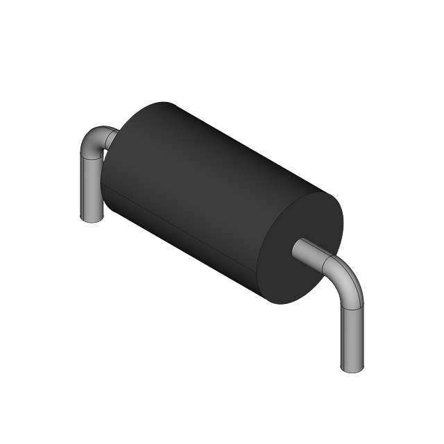
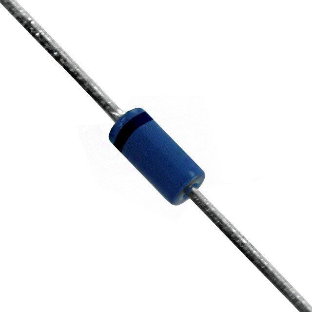
ICGOO电子元器件商城为您提供MKP3V240RLG由ON Semiconductor设计生产,在icgoo商城现货销售,并且可以通过原厂、代理商等渠道进行代购。 MKP3V240RLG价格参考。ON SemiconductorMKP3V240RLG封装/规格:晶闸管 - DIAC,SIDAC, Diac/Sidac Thyristor 220 ~ 250V 1A Axial。您可以下载MKP3V240RLG参考资料、Datasheet数据手册功能说明书,资料中有MKP3V240RLG 详细功能的应用电路图电压和使用方法及教程。
MKP3V240RLG 是安森美(ON Semiconductor)推出的 SIDAC(硅双向触发二极管),属于晶闸管类器件,额定转折电压(VBO)典型值为240 V(±10%),通态电流能力约1 A,具有低触发电流、快速响应和高重复性等特点。

其典型应用场景包括:
✅ 交流电源相位控制电路:用于调光器、电机调速器等,替代传统DIAC驱动TRIAC,实现更稳定的触发时序;
✅ 过压保护与浪涌抑制:在电源输入端作为电压敏感触发元件,配合MOV或可控硅构成自恢复型过压保护电路;
✅ 固态继电器(SSR)及智能开关:作为高可靠性触发单元,提升开关动作的一致性和寿命;
✅ 电子镇流器与LED驱动电源:在启动电路中提供精确的双向触发信号,确保灯管/LED模块可靠启辉;
✅ 家用电器控制板:如微波炉、洗衣机、空调等需AC线路检测与可控通断的场合,用于零交叉检测辅助或简易过压告警。

该器件采用TO-92封装,体积小、成本低、无需外部偏置,适用于对可靠性、温度稳定性及长期一致性要求较高的中低功率AC控制应用。注意:实际设计中需配合限流电阻,并考虑工作环境温度与电压波动裕量,以确保稳定触发与长期可靠性。
| 参数 | 数值 |
| 产品目录 | |
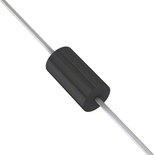
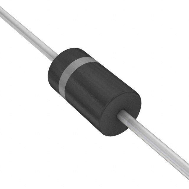
| 描述 | SIDAC 220-250V 1A AXIAL硅对称二端开关元件 240V 0.9A Trigger |
| 产品分类 | 二端交流开关元件,硅对称二端开关元件分离式半导体 |
| 品牌 | ON Semiconductor |
| 产品手册 | |
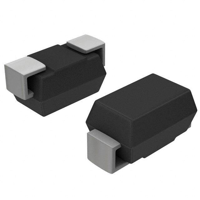
| 产品图片 |
|
| rohs | 符合RoHS无铅 / 符合限制有害物质指令(RoHS)规范要求 |
| 产品系列 | 晶体闸流管,硅对称二端开关元件,ON Semiconductor MKP3V240RLG- |
| 数据手册 | |
| 产品型号 | MKP3V240RLG |
| 不重复通态电流 | 20 A |
| 产品种类 | 硅对称二端开关元件 |
| 供应商器件封装 | 轴向 |
| 保持电流Ih最大值 | 100 mA |
| 关闭状态漏泄电流(在VDRMIDRM下) | 0.01 mA |
| 其它名称 | MKP3V240RLGOSCT |
| 包装 | 剪切带 (CT) |
| 商标 | ON Semiconductor |
| 安装风格 | Through Hole |
| 封装 | Reel |
| 封装/外壳 | DO-201AD,轴向 |
| 封装/箱体 | DO-204AD |
| 工作结温 | - 40 C to + 125 C |
| 工厂包装数量 | 1500 |
| 开启状态电压 | 1.5 V |
| 最大工作温度 | + 125 C |
| 最小工作温度 | - 40 C |
| 标准包装 | 1 |
| 电压-导通 | 220 ~ 250V |
| 电流-保持(Ih)(最大值) | 100mA |
| 电流-击穿 | 200µA |
| 电流-峰值输出 | 1A |
| 系列 | MKP3V |
| 额定重复关闭状态电压VDRM | 180 V |





- 商务部:美国ITC正式对集成电路等产品启动337调查
- 曝三星4nm工艺存在良率问题 高通将骁龙8 Gen1或转产台积电
- 太阳诱电将投资9.5亿元在常州建新厂生产MLCC 预计2023年完工
- 英特尔发布欧洲新工厂建设计划 深化IDM 2.0 战略
- 台积电先进制程称霸业界 有大客户加持明年业绩稳了
- 达到5530亿美元!SIA预计今年全球半导体销售额将创下新高
- 英特尔拟将自动驾驶子公司Mobileye上市 估值或超500亿美元
- 三星加码芯片和SET,合并消费电子和移动部门,撤换高东真等 CEO
- 三星电子宣布重大人事变动 还合并消费电子和移动部门
- 海关总署:前11个月进口集成电路产品价值2.52万亿元 增长14.8%

PDF Datasheet 数据手册内容提取
Thyristors Surface Mount – 120V - 240V > MKP3V120, MKP3V240 MKP3V120, MKP3V240 Pb Description Bidirectional devices designed for direct interface with the ac power line. Upon reaching the breakover voltage in each direction, the device switches from a blocking state to a low voltage on−state. Conduction will continue like a Triac until the main terminal current drops below the holding current. The plastic axial lead package provides high pulse current capability at low cost. Glass passivation insures reliable operation. Features • High Pressure Sodium Vapor Lighting • Strobes and Flashers • Ignitors • High Voltage Regulators • Pulse Generators Axial Lead • Used to Trigger Gates of SCR’s and Triac • Indicates UL Registered − File #E128662 AXIAL LEAD • These are Pb−Free Devices CASE 59 STYLE 2 Functional Diagram Additional Information Datasheet Resources Samples © 2017 Littelfuse, Inc. Specifications are subject to change without notice. Revised: 08/30/17
Thyristors Surface Mount – 120V - 240V > MKP3V120, MKP3V240 Maximum Ratings (T = 25°C unless otherwise noted) J Rating Symbol Value Unit Peak Repetitive Off−State Voltage (Note 1) V , (− 40 to 125°C, Sine Wave, 50 to 60 Hz, Gate Open) DRM V MKP3V120 VRRM ±90 MKP3V240 ±180 On-State RMS Current (All Conduction Angles; T = 80°C, L I ±1.0 A Lead Length = 3/8") T (RMS) Peak Non-Repetitive Surge Current I ±20 A (60 Hz One Cycle, Sine Wave, T = 125°C) TSM J Operating Junction Temperature Range T -40 to +125 °C J Storage Temperature Range T -40 to +150 °C stg Stresses exceeding Maximum Ratings may damage the device. Maximum Ratings are stress ratings only. Functional operation above the Recommended Operating Conditions is not implied. Extended exposure to stresses above the Recommended Operating Conditions may affect device reliability. Thermal Characteristics Rating Symbol Value Unit °C/W Thermal Resistance, Junction−to−Lead (Lead Length = 3/8") R 15 8JL Lead Solder Temperature (Lead Length ≥ 1/16" from Case, 10 s Max) T 260 °C L © 2017 Littelfuse, Inc. Specifications are subject to change without notice. Revised: 08/30/17
Thyristors Surface Mount – 120V - 240V > MKP3V120, MKP3V240 Electrical Characteristics - OFF (T = 25°C unless otherwise noted; Electricals apply in both directions) J Characteristic Symbol Min Typ Max Unit Repetitive Peak Off−State Current (50 to 60 Hz Sine Wave) V = 90V, MKP3V120 I - - 10 µA DRM DRM V = 180V, MKP3V240 DRM Electrical Characteristics - ON (T = 25°C unless otherwise noted; Electricals apply in both directions) J Characteristic Symbol Min Typ Max Unit MKP3V120 110 _ 130 I =200 µA BO Breakover Voltage V V BO MKP3V240 220 _ 250 I =200 µA BO Peak On−State Voltage V – 1.1 1.5 V (I = 1 A Peak, Pulse Width ≤ 300 µs, Duty Cycle ≤ 2%) TM TM Dynamic Holding Current (Sine Wave, 60 Hz, RL = 100 Ω) I _ _ 100 mA H Switching Resistance (Sine Wave, 50 to 60 Hz) R 0.1 _ _ kΩ S Dynamic Characteristics Characteristic Symbol Min Typ Max Unit Critical Rate−of−Rise of On−State Current, Critical Damped Waveform Circuit dv/dt _ 120 − V/µs (I = 130 Ω, Pulse Width = 10 µsec) PK © 2017 Littelfuse, Inc. Specifications are subject to change without notice. Revised: 08/30/17
Thyristors Surface Mount – 120V - 240V > MKP3V120, MKP3V240 Voltage Current Characteristic of SCR Symbol Parameter V Peak Repetitive Forward Off State Voltage I DRM S I I Peak Forward Blocking Current DRM IS V Peak Repetitive Reverse Off State Voltage I S RRM I I Peak Reverse Blocking Current RRM V Maximum On State Voltage ) TM S S (I ) S I Holding Current H Figure 1. Maximum Case Temperature Figure 2. Maximum Ambient Temperature Figure 3. Typical Forward Voltage Figure 4. Typical Power Dissipation © 2017 Littelfuse, Inc. Specifications are subject to change without notice. Revised: 08/30/17
Thyristors Surface Mount – 120V - 240V > MKP3V120, MKP3V240 Thermal Characterstics Figure 5. Thermal Response Typical Characterstics F igure 6. Typical Breakover Current Figure 7. Typical Holding Current © 2017 Littelfuse, Inc. Specifications are subject to change without notice. Revised: 08/30/17
Thyristors Surface Mount – 120V - 240V > MKP3V120, MKP3V240 Dimensions Part Marking System AXIAL LEAD K A D (No Polarity) 1 2 CASE 267 STYLE 2 A B MKP K 3Vxx0 YYWW A= Assembly Location xx = 12 or 24 YY, Y= Year Inches Millimeters WW = Work Week Dim Min Max Min Max (Note: Microdot may be in either location) A 0.287 0.374 7.30 9.50 B 0.189 0.209 4.80 5.30 D 0.047 0.051 1.20 1.30 Ordering Information K 1.000 --- 25.40 --- Device Package Shipping 1. DIMENSIONING AND TOLERANCING PER ANSI Y14.5M, 500 1982. MKP3V120G Units / Box 2. CONTROLLING DIMENSION: INCH. 3. ALL RULES AND NOTES ASSOCIATED WITH JEDEC DO−41 MKP3V120RLG 1500 / 267-04 OBSOLETE, NEW STANDARD 267-05. Tape & Reel Axial Lead 500 MKP3V240G STYLE 2: NO POLARITY Units / Box 1500 / MKP3V240RLG Tape & Reel Disclaimer Notice - Information furnished is believed to be accurate and reliable. However, users should independently evaluate the suitability of and test each product selected for their own applications. Littelfuse products are not designed for, and may not be used in, all applications. Read complete Disclaimer Notice at: www.littelfuse.com/disclaimer-electronics © 2017 Littelfuse, Inc. Specifications are subject to change without notice. Revised: 08/30/17