
 Datasheet下载
- 型号: MKP1848530704K2
- 制造商: Vishay
- 库位|库存: xxxx|xxxx
- 要求:
| 数量阶梯 | 香港交货 | 国内含税 |
| +xxxx | $xxxx | ¥xxxx |
查看当月历史价格
查看今年历史价格
MKP1848530704K2产品简介:
ICGOO电子元器件商城为您提供MKP1848530704K2由Vishay设计生产,在icgoo商城现货销售,并且可以通过原厂、代理商等渠道进行代购。 MKP1848530704K2价格参考。VishayMKP1848530704K2封装/规格:薄膜电容器, 3µF 薄膜电容器 700V 聚丙烯(PP),金属化 径向。您可以下载MKP1848530704K2参考资料、Datasheet数据手册功能说明书,资料中有MKP1848530704K2 详细功能的应用电路图电压和使用方法及教程。
Vishay BC Components 是知名的电子元器件制造商,其 MKP1848530704K2 是一款薄膜电容器,属于金属化聚丙烯(MKP)类型。这类电容器具有低损耗、高稳定性和良好的自愈性能,适用于对可靠性要求较高的场景。

MKP1848530704K2 的典型应用场景包括:

1. 电源滤波:用于开关电源、DC-AC逆变器、UPS系统中,作为EMI/RFI滤波器,抑制高频噪声,提高系统稳定性。

2. 电机控制电路:在变频器、电机驱动器中用于吸收电压尖峰、平滑电流波动,保护功率器件。

3. 照明系统:如LED驱动电源中,用于输入或输出滤波,提升电源效率与稳定性。

4. 工业自动化设备:用于PLC、伺服驱动器等设备的电源管理模块中,提供稳定的滤波支持。

5. 新能源领域:如太阳能逆变器、风力发电变流器中,用于直流链路(DC-link)滤波,承受较高脉动电流。

该电容器具有较高的耐压和耐温性能,适用于中高功率的交流或直流电路中,尤其适合需要长寿命和高可靠性的工业和电力电子应用。
| 参数 | 数值 |
| 产品目录 | |
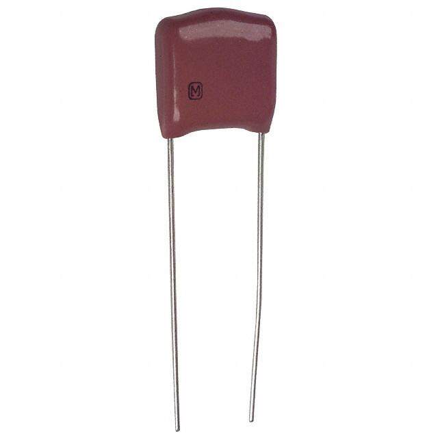
| 描述 | CAP FILM 3UF 700VDC RADIAL薄膜电容器 3uF 700volt 5% 2pin 27.5mm LS |
| ESR | 31.5 mOhms |
| ESR(等效串联电阻) | 31.5 毫欧 |
| 产品分类 | |
| 品牌 | Vishay BC ComponentsVishay / Roederstein |
| 产品手册 | http://www.vishay.com/doc?28164 |
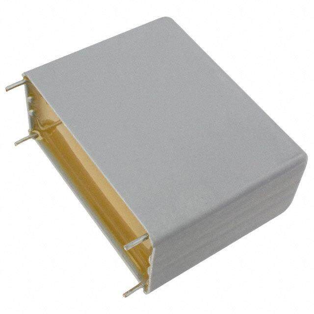
| 产品图片 |
|
| rohs | 符合RoHS无铅 / 符合限制有害物质指令(RoHS)规范要求 |
| 产品系列 | 薄膜电容器,Vishay / Roederstein MKP1848530704K21848 直流链路 |
| 数据手册 | |
| 产品型号 | MKP1848530704K2MKP1848530704K2 |
| 产品 | DC Link Film Capacitors |
| 产品培训模块 | http://www.digikey.cn/PTM/IndividualPTM.page?site=cn&lang=zhs&ptm=24930 |
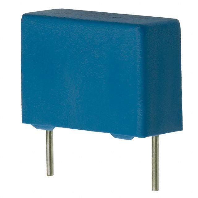
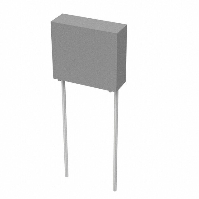
| 产品目录绘图 |
|
| 产品目录页面 | |
| 产品种类 | |
| 介电材料 | 聚丙烯(PP), 金属化 |
| 其它名称 | BC2638 |
| 包装 | 散装 |
| 商标 | Vishay / Roederstein |
| 外壳宽度 | 11 mm |
| 外壳长度 | 32 mm |
| 外壳高度 | 21 mm |
| 大小/尺寸 | 1.260" 长 x 0.433" 宽(32.00mm x 11.00mm) |
| 安装类型 | 通孔 |
| 容差 | 5 %±5% |
| 封装 | Bulk |
| 封装/外壳 | 径向 |
| 工作温度 | -40°C ~ 105°C |
| 应用 | DC 链路,DC 滤波 |
| 引线间距 | 1.083"(27.50mm) |
| 引线间隔 | 27.5 mm |
| 最大工作温度 | + 85 C |
| 最小工作温度 | - 40 C |
| 标准包装 | 130 |
| 特性 | - |
| 电介质 | Polypropylene (PP) |
| 电压额定值DC | 700 V |
| 电容 | 3 uF3.0µF |
| 端接 | PC 引脚 |
| 端接类型 | Radial |
| 系列 | MKP1848 |
| 额定电压-AC | - |
| 额定电压-DC | 700V |
| 高度-安装(最大值) | 0.827"(21.00mm) |


- 商务部:美国ITC正式对集成电路等产品启动337调查
- 曝三星4nm工艺存在良率问题 高通将骁龙8 Gen1或转产台积电
- 太阳诱电将投资9.5亿元在常州建新厂生产MLCC 预计2023年完工
- 英特尔发布欧洲新工厂建设计划 深化IDM 2.0 战略
- 台积电先进制程称霸业界 有大客户加持明年业绩稳了
- 达到5530亿美元!SIA预计今年全球半导体销售额将创下新高
- 英特尔拟将自动驾驶子公司Mobileye上市 估值或超500亿美元
- 三星加码芯片和SET,合并消费电子和移动部门,撤换高东真等 CEO
- 三星电子宣布重大人事变动 还合并消费电子和移动部门
- 海关总署:前11个月进口集成电路产品价值2.52万亿元 增长14.8%
PDF Datasheet 数据手册内容提取
MKP1848 DC-Link www.vishay.com Vishay Roederstein Metallized Polypropylene Film Capacitors DC-Link Capacitor FEATURES • High performance DC filter • Low ESR • High peak current capabilities • High RMS current capabilities • AEC-Q200 qualified • Mounting: radial • Material categorization: for definitions of compliance please see www.vishay.com/doc?99912 APPLICATIONS • High performance DC filtering • HEV / EV: i.e. power train and OBC • Renewable energies inverters • Motor drives • Power supplies QUICK REFERENCE DATA Rated capacitance range 1 μF to 400 μF Capacitance tolerance 5 % Rated voltage range, U 450 V to 1200 V NDC Climatic testing class 40 / 105 / 56 Rated temperature 85 °C Maximum permissible case temperature 105 °C, observing voltage derating Maximum applicable peak to peak ripple voltage 0.2 x U NDC Reference standards IEC 61071, IEC 60068 Dielectric Polypropylene film Electrodes Metallized dielectric capacitor Construction Mono construction Encapsulation Plastic case, sealed with resin; flame retardant Terminals Tinned wires Self inductance (L ) < 1 nH per mm of lead spacing S Withstanding DC voltage between terminals (1) 1.5 UNDC for 10 s, cut off current 10 mA, rise time 1000 V/s RC between leads, after 1 min > 10 000 s Insulation resistance For UNDC 500 V measuring voltage 100 V For U > 500 V measuring voltage 500 V NDC Useful life time: > 100 000 h at U and 70 °C Life time expectancy NDC FIT: < 10 x 10-9/h (10 per 109 component h) at 0.5 x U , 40 °C NDC C-value; tolerance; rated voltage; code for dielectric material; Marking code for manufacturing origin; manufacturer’s type designation; manufacturer’s logo; year and week of manufacture Notes • For more detailed data and test requirements, contact dc-film@vishay.com • For general information like characteristics and definitions used for film capacitors follow the link: www.vishay.com/doc?28147 (1) See document “Voltage Proof Test for Metalized Film Capacitors” (www.vishay.com/doc?28169) DC VOLTAGE RATINGS U at 85 °C 450 V 700 V 800 V 900 V 1100 V 1200 V NDC U at 70 °C 500 V 800 V 900 V 1100 V 1350 V 1500 V OPDC U at 105 °C 300 V 500 V 570 V 650 V 800 V 850 V OPDC Revision: 25-Oct-17 1 Document Number: 28164 For technical questions, contact: dc-film@vishay.com THIS DOCUMENT IS SUBJECT TO CHANGE WITHOUT NOTICE. THE PRODUCTS DESCRIBED HEREIN AND THIS DOCUMENT ARE SUBJECT TO SPECIFIC DISCLAIMERS, SET FORTH AT www.vishay.com/doc?91000
MKP1848 DC-Link www.vishay.com Vishay Roederstein COMPOSITION OF CATALOG NUMBER MULTIPLIER CAPACITANCE (nF) (numerically) 10 4 Example: P1 PITCH 100 5 512 1200 nF 1.2 µF (mm) CODE 1000 6 612 12 000 nF 12 µF 27.5 K 10 000 7 712 120 000 nF 120 µF 37.5 P 52.5 Y MKP 1848 6 12 09 4 P 4 TYPE CONSTRUCTION SPECIAL CODE FOR TERMINAL METALLIZED POLYPROPYLENE VOLTAGE TOLERANCE 2 2 pins U = 45 = 450 V 4 ± 5 % 4 4 pins P2 = 10.2 mm N DC U = 70 = 700 V 5 4 pins P2 = 20.3 mm N DC U = 08 = 800 V (1) Customized N DC U = 09 = 900 V N DC U = 91 = 1100 V N DC UN = 92 = 1200 VDC Note (1) Tabs terminals or customized terminals are available on request DIMENSIONS in millimeters 2 PINS w I h P1 6 - 1 Ø dt P1 ± 0.4 - PCM 27.5 mm P1 ± 0.5 - PCM ≥ 37.5 mm 4 PINS I w Marking P2 P2 h P1 6 - 2 Ø dt P1 ± 0.5 P2 ± 0.5 Revision: 25-Oct-17 2 Document Number: 28164 For technical questions, contact: dc-film@vishay.com THIS DOCUMENT IS SUBJECT TO CHANGE WITHOUT NOTICE. THE PRODUCTS DESCRIBED HEREIN AND THIS DOCUMENT ARE SUBJECT TO SPECIFIC DISCLAIMERS, SET FORTH AT www.vishay.com/doc?91000
MKP1848 DC-Link www.vishay.com Vishay Roederstein DIMENSIONS in millimeters 6 PINS w I Marking P2 h P2 6 - 2 P1 P1 Ø dt P2 2 x P2 12 PINS I w Marking P1 h P2 6 - 2 P1 2 x P2 Ø dt 3 x P2 P2 2 x P2 4 x P2 3 x P2 5 x P2 4 x P2 5 x P2 Notes • Ø dt ± 10 % of standard diameter specified • For pitch 27.5 mm marking will be either on top or front side. For pitch 37.5 mm marking will be on front side only ELECTRICAL DATA AND ORDERING CODE tan UNDC DIMENSION (5) IRMS (2) ESR (3) 10 kHz AT CAP. (8) (mm) P1 P2 dV/dt IPEAK (A) (m) (< 10-4) (4) ORDERING CODE (1) 85 °C (μF) (mm) (mm) (V/μs) (A) (V) w h l 2 4 2 4 2 4 PINS PINS PINS PINS PINS PINS U AT 70 °C = 500 V, U AT 105 °C = 300 V OPDC OPDC 1 9.0 19.0 32.0 27.5 - 75 75 2.5 - 54 - 85 - MKP1848510454K2 2 9.0 19.0 32.0 27.5 - 75 150 3 - 34.5 - 85 - MKP1848520454K2 3 11.0 21.0 32.0 27.5 - 75 225 4 - 23.0 - 85 - MKP1848530454K2 4 11.0 21.0 32.0 27.5 - 75 300 4 - 20.5 - 85 - MKP1848540454K2 5 13.0 23.0 32.0 27.5 - 75 375 5 - 16.5 - 85 - MKP1848550454K2 6 15.0 25.0 32.0 27.5 - 75 450 6 - 13.5 - 85 - MKP1848560454K2 450 7 15.0 25.0 32.0 27.5 - 75 525 6.5 - 11.5 - 85 - MKP1848570454K2 8 18.0 28.0 32.0 27.5 - 75 600 8.5 - 8.5 - 85 - MKP1848580454K2 9 18.0 28.0 32.0 27.5 - 75 675 8.5 - 9.0 - 85 - MKP1848590454K2 10 18.0 28.0 32.0 27.5 - 75 750 9 - 8.0 - 85 - MKP1848610454K2 12 21.0 31.0 32.0 27.5 - 75 900 10 - 7.0 - 85 - MKP1848612454K2 15 20.0 35.0 32.0 27.5 - 75 1125 11.5 - 6.0 - 85 - MKP1848615454K2 10 18.5 35.5 43.0 37.5 10.2 40 400 7.5 8 13.5 12.0 160 140 MKP1848610454P* Revision: 25-Oct-17 3 Document Number: 28164 For technical questions, contact: dc-film@vishay.com THIS DOCUMENT IS SUBJECT TO CHANGE WITHOUT NOTICE. THE PRODUCTS DESCRIBED HEREIN AND THIS DOCUMENT ARE SUBJECT TO SPECIFIC DISCLAIMERS, SET FORTH AT www.vishay.com/doc?91000
MKP1848 DC-Link www.vishay.com Vishay Roederstein ELECTRICAL DATA AND ORDERING CODE tan UNDC DIMENSION (5) IRMS (2) ESR (3) 10 kHz AT CAP. (8) (mm) P1 P2 dV/dt IPEAK (A) (m) (< 10-4) (4) ORDERING CODE (1) 85 °C (μF) (mm) (mm) (V/μs) (A) (V) w h l 2 4 2 4 2 4 PINS PINS PINS PINS PINS PINS U AT 70 °C = 500 V, U AT 105 °C = 300 V OPDC OPDC 12 18.5 35.5 43.0 37.5 10.2 40 480 8 8.5 11.5 10.0 160 140 MKP1848612454P* 15 18.5 35.5 43.0 37.5 10.2 40 600 9 10 9.0 8.0 160 140 MKP1848615454P* 20 21.5 38.5 43.0 37.5 10.2 40 800 11 12 7.0 6.0 160 140 MKP1848620454P* 22 21.5 38.5 43.0 37.5 10.2 40 880 11 11.5 7.5 6.5 160 140 MKP1848622454P* 25 21.5 38.5 43.0 37.5 10.2 40 1000 11.5 12.5 6.5 5.5 160 140 MKP1848625454P* 30 24.0 44.0 42.0 37.5 10.2 40 1200 13.5 15 5.5 4.5 160 140 MKP1848630454P* 35 30.0 45.0 42.0 37.5 10.2 / 20.3 40 1400 17 18.5 4.0 3.5 160 140 MKP1848635454P* 40 30.0 45.0 42.0 37.5 10.2 / 20.3 40 1600 17 18.5 4.0 3.5 160 140 MKP1848640454P* 40 25.0 45.0 57.5 52.5 10.2 20 800 13 13.5 6.5 6.0 310 280 MKP1848640454Y* 45 25.0 45.0 57.5 52.5 10.2 20 900 12.5 13.5 7.0 6.0 310 280 MKP1848645454Y* 450 50 30.0 45.0 57.5 52.5 20.3 20 1000 15 15.5 5.5 5.0 310 280 MKP1848650454Y* 55 30.0 45.0 57.5 52.5 20.3 20 1100 15 15.5 5.5 5.0 310 280 MKP1848655454Y* 60 30.0 45.0 57.5 52.5 20.3 20 1200 15.5 16.5 5.0 4.5 310 280 MKP1848660454Y* 65 35.0 50.0 57.5 52.5 20.3 20 1300 19 20.5 4.0 3.5 310 280 MKP1848665454Y* 70 35.0 50.0 57.5 52.5 20.3 20 1400 18 19 4.5 4.0 310 280 MKP1848670454Y* 75 35.0 50.0 57.5 52.5 20.3 20 1500 19 20.5 4.0 3.5 310 280 MKP1848675454Y* 80 35.0 50.0 57.5 52.5 20.3 20 1600 19 20.5 4.0 3.5 310 280 MKP1848680454Y* 90 45.0 45.0 57.5 52.5 20.3 20 1800 - 21.5 - 3.0 - 280 MKP1848690454Y5 95 45.0 45.0 57.5 52.5 20.3 20 1900 - 21.5 - 3.0 - 280 MKP1848695454Y5 100 45.0 45.0 57.5 52.5 20.3 20 2000 - 23.5 - 2.5 - 280 MKP1848710454Y5 200 70.0 65.0 57.5 52.5 20.3 20 2000 - 30.5 - 2.0 - 310 MKP1848720454Y5 (6) 400 130 65.0 57.5 52.5 20.3 10 4000 - 50.5 - 1.5 - 380 MKP1848740454Y5 (7) U AT 70 °C = 800 V, U AT 105 °C = 500 V OPDC OPDC 1 9 19 32 27.5 - 75 75 2.5 - 54 - 68 - MKP1848510704K2 2 9 19 32 27.5 - 75 150 3 - 34.5 - 68 - MKP1848520704K2 3 11 21 32 27.5 - 75 225 4 - 23 - 68 - MKP1848530704K2 4 13 23 32 27.5 - 75 300 5 - 17 - 68 - MKP1848540704K2 5 15 25 32 27.5 - 75 375 6 - 14 - 68 - MKP1848550704K2 6 18 28 32 27.5 - 75 450 7.5 - 11.5 - 68 - MKP1848560704K2 7 18 28 32 27.5 - 75 525 8 - 10 - 68 - MKP1848570704K2 8 18 28 32 27.5 - 75 600 8.5 - 8.5 - 68 - MKP1848580704K2 700 9 21 31 32 27.5 - 75 675 10 - 7.5 - 68 - MKP1848590704K2 10 21 31 32 27.5 - 75 750 10 - 7 - 68 - MKP1848610704K2 12 20 35 32 27.5 - 75 900 11.5 - 6 - 68 - MKP1848612704K2 10 18.5 35.5 43 37.5 10.2 40 400 7.5 8 13.5 12 135 120 MKP1848610704P* 12 18.5 35.5 43 37.5 10.2 40 480 8 8.5 11.5 10 135 120 MKP1848612704P* 15 18.5 35.5 43 37.5 10.2 40 600 9 10 9 8 135 120 MKP1848615704P* 20 21.5 38.5 43 37.5 10.2 40 800 11 12 7 6 135 120 MKP1848620704P* 22 24 44 42 37.5 10.2 40 880 13 13.5 6 5.5 135 120 MKP1848622704P* 25 24 44 42 37.5 10.2 40 1000 13.5 14.5 5.5 5 135 120 MKP1848625704P* 30 30 45 42 37.5 10.2 / 20.3 40 1200 16 17 4.5 4 135 120 MKP1848630704P* Revision: 25-Oct-17 4 Document Number: 28164 For technical questions, contact: dc-film@vishay.com THIS DOCUMENT IS SUBJECT TO CHANGE WITHOUT NOTICE. THE PRODUCTS DESCRIBED HEREIN AND THIS DOCUMENT ARE SUBJECT TO SPECIFIC DISCLAIMERS, SET FORTH AT www.vishay.com/doc?91000
MKP1848 DC-Link www.vishay.com Vishay Roederstein ELECTRICAL DATA AND ORDERING CODE tan UNDC DIMENSION (5) IRMS (2) ESR (3) 10 kHz AT CAP. (8) (mm) P1 P2 dV/dt IPEAK (A) (m) (< 10-4) (4) ORDERING CODE (1) 85 °C (μF) (mm) (mm) (V/μs) (A) (V) w h l 2 4 2 4 2 4 PINS PINS PINS PINS PINS PINS U AT 70 °C = 800 V, U AT 105 °C = 500 V OPDC OPDC 35 30 45 42 37.5 10.2 / 20.3 40 1400 17 18.5 4 3.5 135 120 MKP1848635704P* 30 25 45 57.5 52.5 10.2 20 600 11 12 9 8 270 240 MKP1848630704Y* 35 25 45 57.5 52.5 10.2 20 700 12 12.5 7.5 7 270 240 MKP1848635704Y* 40 25 45 57.5 52.5 10.2 20 800 13 13.5 6.5 6 270 240 MKP1848640704Y* 45 30 45 57.5 52.5 20.3 20 900 14.5 15 6 5.5 270 240 MKP1848645704Y* 50 30 45 57.5 52.5 20.3 20 1000 15 15.5 5.5 5 270 240 MKP1848650704Y* 700 55 35 50 57.5 52.5 20.3 20 1100 17 18 5 4.5 270 240 MKP1848655704Y* 60 35 50 57.5 52.5 20.3 20 1200 18 19 4.5 4 270 240 MKP1848660704Y* 65 35 50 57.5 52.5 20.3 20 1300 19 20.5 4 3.5 270 240 MKP1848665704Y* 70 45 45 57.5 52.5 20.3 20 1400 - 20 - 3.5 - 240 MKP1848670704Y5 75 45 45 57.5 52.5 20.3 20 1500 - 21.5 - 3 - 240 MKP1848675704Y5 80 45 45 57.5 52.5 20.3 20 1600 - 21.5 - 3 - 240 MKP1848680704Y5 160 70 65 57.5 52.5 20.3 20 3200 - 30.5 - 2.5 - 280 MKP1848716704Y5 (6) 320 130 65 57.5 52.5 20.3 20 6400 - 54 - 1.3 - 280 MKP1848732704Y5 (7) U AT 70 °C = 900 V, U AT 105 °C = 570 V OPDC OPDC 1 9 19 32 27.5 - 75 75 2 - 62.5 - 60 - MKP1848510084K2 2 11 21 32 27.5 - 75 150 3.5 - 31 - 60 - MKP1848520084K2 3 13 23 32 27.5 - 75 225 4.5 - 21 - 60 - MKP1848530084K2 4 15 25 32 27.5 - 75 300 5.5 - 15.5 - 60 - MKP1848540084K2 5 18 28 32 27.5 - 75 375 7 - 12.5 - 60 - MKP1848550084K2 6 18 28 32 27.5 - 75 450 7.5 - 10.5 - 60 - MKP1848560084K2 7 21 31 32 27.5 - 75 525 9 - 9 - 60 - MKP1848570084K2 8 21 31 32 27.5 - 75 600 9.5 - 8 - 60 - MKP1848580084K2 9 20 35 32 27.5 - 75 675 10 - 8 - 60 - MKP1848590084K2 10 18.5 35.5 43 37.5 10.2 40 400 8 8.5 12.5 11 122 110 MKP1848610084P* 12 18.5 35.5 43 37.5 10.2 40 480 8.5 9 10.5 9 122 110 MKP1848612084P* 800 15 21.5 38.5 43 37.5 10.2 40 600 10 11 8.5 7.5 122 110 MKP1848615084P* 20 24 44 42 37.5 10.2 40 800 13 13.5 6 5.5 122 110 MKP1848620084P* 22 30 45 42 37.5 10.2 / 20.3 40 880 14.5 15.5 5.5 5 122 110 MKP1848622084P* 25 30 45 42 37.5 10.2 / 20.3 40 1000 15.5 16 5 4.5 122 110 MKP1848625084P* 30 25 45 57.5 52.5 10.2 10 300 12 12 8 7.5 240 215 MKP1848630084Y* 35 30 45 57.5 52.5 20.3 10 350 13 14.5 7 6 240 215 MKP1848635084Y* 40 30 45 57.5 52.5 20.3 10 400 14.5 15 6 5.5 240 215 MKP1848640084Y* 45 35 50 57.5 52.5 20.3 10 450 16 17 5.5 5 240 215 MKP1848645084Y* 50 35 50 57.5 52.5 20.3 10 500 17 18 5 4.5 240 215 MKP1848650084Y* 55 45 45 57.5 52.5 20.3 10 550 - 18.5 - 4 - 215 MKP1848655084Y5 60 45 45 57.5 52.5 20.3 10 600 - 20 - 3.5 - 215 MKP1848660084Y5 120 70 65 57.5 52.5 20.3 10 1600 - 27 - 3.2 - 215 MKP1848712084Y5 (6) 240 130 65 57.5 52.5 20.3 10 3200 - 48.5 - 1.6 - 215 MKP1848724084Y5 (7) Revision: 25-Oct-17 5 Document Number: 28164 For technical questions, contact: dc-film@vishay.com THIS DOCUMENT IS SUBJECT TO CHANGE WITHOUT NOTICE. THE PRODUCTS DESCRIBED HEREIN AND THIS DOCUMENT ARE SUBJECT TO SPECIFIC DISCLAIMERS, SET FORTH AT www.vishay.com/doc?91000
MKP1848 DC-Link www.vishay.com Vishay Roederstein ELECTRICAL DATA AND ORDERING CODE tan UNDC DIMENSION (5) IRMS (2) ESR (3) 10 kHz AT CAP. (8) (mm) P1 P2 dV/dt IPEAK (A) (m) (< 10-4) (4) ORDERING CODE (1) 85 °C (μF) (mm) (mm) (V/μs) (A) (V) w h l 2 4 2 4 2 4 PINS PINS PINS PINS PINS PINS U AT 70 °C = 1100 V, U AT 105 °C = 650 V OPDC OPDC 1 9 19 32 27.5 - 40 40 2 - 63 - 50 - MKP1848510094K2 2 13 23 32 27.5 - 80 160 3.5 - 32 - 50 - MKP1848520094K2 3 15 25 32 27.5 - 80 240 5 - 21 - 50 - MKP1848530094K2 4 18 28 32 27.5 - 80 320 6 - 16 - 50 - MKP1848540094K2 5 21 31 32 27.5 - 80 400 7.5 - 13 - 50 - MKP1848550094K2 6 21 31 32 27.5 - 80 480 8.5 - 10 - 50 - MKP1848560094K2 7 20 35 32 27.5 - 80 560 9 - 9 - 50 - MKP1848570094K2 5 18.5 35.5 43 37.5 10.2 20 100 6 6.5 21 19 100 90 MKP1848550094P* 6 18.5 35.5 43 37.5 10.2 40 240 6.5 7 18 16 100 90 MKP1848560094P* 7 18.5 35.5 43 37.5 10.2 40 280 6.5 7 18 16 100 90 MKP1848570094P* 8 18.5 35.5 43 37.5 10.2 40 320 7 7.5 16 14 100 90 MKP1848580094P* 9 18.5 35.5 43 37.5 10.2 40 360 7.5 8 14 12 100 90 MKP1848590094P* 10 21.5 38.5 43 37.5 10.2 40 400 8.5 9 12 11 100 90 MKP1848610094P* 900 12 21.5 38.5 43 37.5 10.2 40 480 9.5 10 10 9 100 90 MKP1848612094P* 15 24 44 42 37.5 10.2 40 600 11 12 8 7 100 90 MKP1848615094P* 16 24 44 42 37.5 10.2 40 640 11 12 8 7 100 90 MKP1848616094P* 20 30 45 42 37.5 10.2 / 20.3 40 800 14 15.5 6 5 100 90 MKP1848620094P* 15 25 45 57.5 52.5 10.2 20 300 9 9.5 14 12 200 185 MKP1848615094Y* 20 25 45 57.5 52.5 10.2 20 400 9.5 10 12 11 200 185 MKP1848620094Y* 22 25 45 57.5 52.5 10.2 20 440 10 10.5 11 10 200 185 MKP1848622094Y* 25 30 45 57.5 52.5 20.3 20 500 11 11.5 10 9 200 185 MKP1848625094Y* 30 30 45 57.5 52.5 20.3 20 600 12.5 13 8 7 200 185 MKP1848630094Y* 35 35 50 57.5 52.5 20.3 20 700 14.5 15.5 7 6 200 185 MKP1848635094Y* 40 35 50 57.5 52.5 20.3 20 800 15.5 17 6 5 200 185 MKP1848640094Y* 45 45 45 57.5 52.5 20.3 20 900 - 16.5 - 5 - 185 MKP1848645094Y5 50 45 45 57.5 52.5 20.3 20 1000 - 18.5 - 4 - 185 MKP1848650094Y5 100 70 65 57.5 52.5 20.3 20 2000 - 26.5 - 3.3 - 205 MKP1848710094Y5 (6) 200 130 65 57.5 52.5 20.3 20 4000 - 48.5 - 1.6 - 205 MKP1848720094Y5 (7) U AT 70 °C = 1350 V, U AT 105 °C = 800 V OPDC OPDC 1 11 21 32 27.5 - 95 95 3 - 45.5 - 45 - MKP1848510914K2 2 15 25 32 27.5 - 95 190 4.5 - 23 - 45 - MKP1848520914K2 3 18 28 32 27.5 - 95 285 6 - 15.5 - 45 - MKP1848530914K2 4 21 31 32 27.5 - 95 380 8 - 11.5 - 45 - MKP1848540914K2 5 20 35 32 27.5 - 95 475 9 - 9.5 - 45 - MKP1848550914K2 1100 5 18.5 35.5 43 37.5 10.2 45 225 6.5 7 18 16 90 80 MKP1848550914P* 6 18.5 35.5 43 37.5 10.2 45 270 7 7.5 15 13.5 90 80 MKP1848560914P* 7 21.5 38.5 43 37.5 10.2 45 315 8 8.5 13 11.5 90 80 MKP1848570914P* 8 21.5 38.5 43 37.5 10.2 45 360 9 9.5 11 10 90 80 MKP1848580914P* 9 24 44 42 37.5 10.2 45 405 10 10.5 10 9 90 80 MKP1848590914P* 10 24 44 42 37.5 10.2 45 450 10.5 11 9 8 90 80 MKP1848610914P* 12 30 45 42 37.5 10.2 / 20.3 45 540 12.5 13.5 7.5 6.5 90 80 MKP1848612914P* Revision: 25-Oct-17 6 Document Number: 28164 For technical questions, contact: dc-film@vishay.com THIS DOCUMENT IS SUBJECT TO CHANGE WITHOUT NOTICE. THE PRODUCTS DESCRIBED HEREIN AND THIS DOCUMENT ARE SUBJECT TO SPECIFIC DISCLAIMERS, SET FORTH AT www.vishay.com/doc?91000
MKP1848 DC-Link www.vishay.com Vishay Roederstein ELECTRICAL DATA AND ORDERING CODE tan UNDC DIMENSION (5) IRMS (2) ESR (3) 10 kHz AT CAP. (8) (mm) P1 P2 dV/dt IPEAK (A) (m) (< 10-4) (4) ORDERING CODE (1) 85 °C (μF) (mm) (mm) (V/μs) (A) (V) w h l 2 4 2 4 2 4 PINS PINS PINS PINS PINS PINS U AT 70 °C = 1350 V, U AT 105 °C = 800 V OPDC OPDC 10 25 45 57.5 52.5 10.2 23 230 8 8.5 18 16 175 155 MKP1848610914Y* 12 25 45 57.5 52.5 10.2 23 276 8.5 9 15 13 175 155 MKP1848612914Y* 15 25 45 57.5 52.5 10.2 23 345 9.5 10.5 12 10.5 175 155 MKP1848615914Y* 20 30 45 57.5 52.5 20.3 23 460 11.5 12.5 9 8 175 155 MKP1848620914Y* 22 35 50 57.5 52.5 20.3 23 506 13.5 14.5 8 7 175 155 MKP1848622914Y* 1100 25 35 50 57.5 52.5 20.3 23 575 14.5 15 7 6.5 175 155 MKP1848625914Y* 30 45 45 57.5 52.5 20.3 23 690 - 16.5 - 5 - 155 MKP1848630914Y5 60 70 65 57.5 52.5 20.3 23 1380 - 40 - 2.5 - 180 MKP1848660914Y5 (6) 70 70 65 57.5 52.5 20.3 23 1610 - 34.5 - 2 - 180 MKP1848670914Y5 (6) 120 130 65 57.5 52.5 20.3 23 2760 - 39.5 - 2.4 - 180 MKP1848712914Y5 (7) 140 130 65 57.5 52.5 20.3 23 3220 - 43.5 - 2 - 180 MKP1848714914Y5 (7) U AT 70 °C = 1500 V, U AT 105 °C = 850 V OPDC OPDC 1 11 21 32 27.5 - 100 100 3 - 43 - 40 - MKP1848510924K2 2 15 25 32 27.5 - 100 200 5 - 21.5 - 40 - MKP1848520924K2 3 18 28 32 27.5 - 100 300 6.5 - 14.5 - 40 - MKP1848530924K2 4 21 31 32 27.5 - 100 400 8 - 11 - 40 - MKP1848540924K2 5 18.5 35.5 43 37.5 10.2 48 240 6.5 7 17 15 80 70 MKP1848550924P* 6 18.5 35.5 43 37.5 10.2 48 288 7.5 8 14 12.5 80 70 MKP1848560924P* 7 21.5 38.5 43 37.5 10.2 48 336 8.5 9 12 11 80 70 MKP1848570924P* 8 21.5 38.5 43 37.5 10.2 48 384 9 9.5 10.5 9.5 80 70 MKP1848580924P* 9 24 44 42 37.5 10.2 48 432 10.5 11 9.5 8.5 80 70 MKP1848590924P* 1200 10 24 44 42 37.5 10.2 48 480 11 11.5 8.5 7.5 80 70 MKP1848610924P* 12 30 45 42 37.5 10.2 / 20.3 48 576 13 13.5 7 6.5 80 70 MKP1848612924P* 10 25 45 57.5 52.5 10.2 24 240 8 8.5 17 15 165 150 MKP1848610924Y* 12 25 45 57.5 52.5 10.2 24 288 9 9.5 14 12.5 165 150 MKP1848612924Y* 15 25 45 57.5 52.5 10.2 24 360 10 10.5 11 10 165 150 MKP1848615924Y* 20 35 50 57.5 52.5 20.3 24 480 13 14 8.5 7.5 165 150 MKP1848620924Y* 22 35 50 57.5 52.5 20.3 24 528 14 14.5 7.5 7 165 150 MKP1848622924Y* 25 35 50 57.5 52.5 20.3 24 600 15 15.5 6.5 6 165 150 MKP1848625924Y* 30 45 45 57.5 52.5 20.3 24 720 - 16.5 - 5 - 150 MKP1848630924Y5 60 70 65 57.5 52.5 20.3 24 1440 - 23 - 4.5 - 170 MKP1848660924Y5 (6) 120 130 65 57.5 52.5 20.3 24 2280 - 40.5 - 2.3 - 170 MKP1848712924Y5 (7) Notes (1) Change the * symbol with special code for the terminals (2) Maximum RMS current at 10 kHz, +85 °C, t = +15 °C, capacitance tolerance ± 5 % (3) Equivalent series resistance typical values at f = 10 kHz to 100 kHz for P = 27.5 mm, at f = 10 kHz to 70 kHz for P = 37.5 mm, at f = 10 kHz to 50 kHz for P = 52.5 mm (4) Maximum tan values (5) Standard dimension (6) 6 pins (7) 12 pins (8) Intermediate capacitance values available on request Revision: 25-Oct-17 7 Document Number: 28164 For technical questions, contact: dc-film@vishay.com THIS DOCUMENT IS SUBJECT TO CHANGE WITHOUT NOTICE. THE PRODUCTS DESCRIBED HEREIN AND THIS DOCUMENT ARE SUBJECT TO SPECIFIC DISCLAIMERS, SET FORTH AT www.vishay.com/doc?91000
MKP1848 DC-Link www.vishay.com Vishay Roederstein PACKAGING INFORMATION U NDC HEIGHT CAP. (5) MASS SPQ (2) AT 85 °C Ø dt ORDERING CODE (1) (mm) (μF) (g) (pcs) (V) U AT 70 °C = 500 V, U AT 105 °C = 300 V OPDC OPDC 19 1 0.8 MKP1848510454K2 6 160 19 2 0.8 MKP1848520454K2 5.5 160 21 3 0.8 MKP1848530454K2 8.5 130 21 4 0.8 MKP1848540454K2 8.5 130 23 5 0.8 MKP1848550454K2 10.5 115 25 6 0.8 MKP1848560454K2 12.5 100 25 7 0.8 MKP1848570454K2 11.5 100 28 8 0.8 MKP1848580454K2 15 80 28 9 0.8 MKP1848590454K2 16 80 28 10 0.8 MKP1848610454K2 15 80 31 12 0.8 MKP1848612454K2 21.5 65 35 15 0.8 MKP1848615454K2 20 70 35.5 10 1.0 MKP1848610454P* 34 105 35.5 12 1.0 MKP1848612454P* 32 105 35.5 15 1.0 MKP1848615454P* 30 105 38.5 20 1.0 MKP1848620454P* 36 91 38.5 22 1.0 MKP1848622454P* 38 91 450 38.5 25 1.0 MKP1848625454P* 36 91 44 30 1.0 MKP1848630454P* 48 77 45 35 1.0 MKP1848635454P* 57 63 45 40 1.0 MKP1848640454P* 60 63 45 40 1.2 MKP1848640454Y* 66 55 45 45 1.2 MKP1848645454Y* 70 55 45 50 1.2 MKP1848650454Y* 88 45 45 55 1.2 MKP1848655454Y* 96 45 45 60 1.2 MKP1848660454Y* 91 45 50 65 1.2 MKP1848665454Y* 100 40 50 70 1.2 MKP1848670454Y* 112 40 50 75 1.2 MKP1848675454Y* 108 40 50 80 1.2 MKP1848680454Y* 102 40 45 90 1.2 MKP1848690454Y5 127 30 45 95 1.2 MKP1848695454Y5 124 30 45 100 1.2 MKP1848710454Y5 120 30 65 200 1.2 MKP1848720454Y5 (3) 266 20 65 400 1.2 MKP1848740454Y5 (4) 490 10 U AT 70 °C = 800 V, U AT 105 °C = 500 V OPDC OPDC 19 1 0.8 MKP1848510704K2 6 160 19 2 0.8 MKP1848520704K2 5.5 160 21 3 0.8 MKP1848530704K2 8.5 130 23 4 0.8 MKP1848540704K2 10.5 115 25 5 0.8 MKP1848550704K2 12 100 28 6 0.8 MKP1848560704K2 17 80 28 7 0.8 MKP1848570704K2 16 80 700 28 8 0.8 MKP1848580704K2 15 80 31 9 0.8 MKP1848590704K2 22 65 31 10 0.8 MKP1848610704K2 21 65 35 12 0.8 MKP1848612704K2 20 70 35.5 10 1.0 MKP1848610704P* 34 105 35.5 12 1.0 MKP1848612704P* 32 105 35.5 15 1.0 MKP1848615704P* 30 105 38.5 20 1.0 MKP1848620704P* 36 91 Revision: 25-Oct-17 8 Document Number: 28164 For technical questions, contact: dc-film@vishay.com THIS DOCUMENT IS SUBJECT TO CHANGE WITHOUT NOTICE. THE PRODUCTS DESCRIBED HEREIN AND THIS DOCUMENT ARE SUBJECT TO SPECIFIC DISCLAIMERS, SET FORTH AT www.vishay.com/doc?91000
MKP1848 DC-Link www.vishay.com Vishay Roederstein PACKAGING INFORMATION U NDC HEIGHT CAP. (5) MASS SPQ (2) AT 85 °C Ø dt ORDERING CODE (1) (mm) (μF) (g) (pcs) (V) U AT 70 °C = 800 V, U AT 105 °C = 500 V OPDC OPDC 44 22 1.0 MKP1848622704P* 49 77 44 25 1.0 MKP1848625704P* 47 77 45 30 1.0 MKP1848630704P* 62 63 45 35 1.0 MKP1848635704P* 55 63 45 30 1.2 MKP1848630704Y* 76 55 45 35 1.2 MKP1848635704Y* 71 55 45 40 1.2 MKP1848640704Y* 66 55 45 45 1.2 MKP1848645704Y* 95 45 700 45 50 1.2 MKP1848650704Y* 88 45 50 55 1.2 MKP1848655704Y* 112 40 50 60 1.2 MKP1848660704Y* 107 40 50 65 1.2 MKP1848665704Y* 100 40 45 70 1.2 MKP1848670704Y5 128 30 45 75 1.2 MKP1848675704Y5 123 30 45 80 1.2 MKP1848680704Y5 119 30 65 160 1.2 MKP1848716704Y5 (3) 264 20 65 320 1.2 MKP1848732704Y5 (4) 359 10 U AT 70 °C = 900 V, U AT 105 °C = 570 V OPDC OPDC 19 1 0.8 MKP1848510084K2 6.5 160 21 2 0.8 MKP1848520084K2 9 130 23 3 0.8 MKP1848530084K2 11 115 25 4 0.8 MKP1848540084K2 12 100 28 5 0.8 MKP1848550084K2 17 80 28 6 0.8 MKP1848560084K2 16 80 31 7 0.8 MKP1848570084K2 23 65 31 8 0.8 MKP1848580084K2 21 65 35 9 0.8 MKP1848590084K2 21 70 35.5 10 1.0 MKP1848610084P* 32 105 35.5 12 1.0 MKP1848612084P* 30 105 38.5 15 1.0 MKP1848615084P* 37 91 44 20 1.0 MKP1848620084P* 47 77 45 22 1.0 MKP1848622084P* 65 63 45 25 1.0 MKP1848625084P* 61 63 45 30 1.2 MKP1848630084Y* 69 55 800 45 35 1.2 MKP1848635084Y* 97 45 45 40 1.2 MKP1848640084Y* 91 45 50 45 1.2 MKP1848645084Y* 112 40 50 50 1.2 MKP1848650084Y* 104 40 45 55 1.2 MKP1848655084Y5 131 30 45 60 1.2 MKP1848660084Y5 125 30 65 120 1.2 MKP1848712084Y5 (3) 276 20 65 240 1.2 MKP1848724084Y5 (4) 393 10 19 1 0.8 MKP1848510094K2 6 160 23 2 0.8 MKP1848520094K2 11 115 25 3 0.8 MKP1848530094K2 12 100 28 4 0.8 MKP1848540094K2 16.5 80 31 5 0.8 MKP1848550094K2 22.5 65 31 6 0.8 MKP1848560094K2 21 65 35 7 0.8 MKP1848570094K2 21 70 35.5 5 1.0 MKP1848550094P* 32 105 35.5 6 1.0 MKP1848560094P* 30 105 Revision: 25-Oct-17 9 Document Number: 28164 For technical questions, contact: dc-film@vishay.com THIS DOCUMENT IS SUBJECT TO CHANGE WITHOUT NOTICE. THE PRODUCTS DESCRIBED HEREIN AND THIS DOCUMENT ARE SUBJECT TO SPECIFIC DISCLAIMERS, SET FORTH AT www.vishay.com/doc?91000
MKP1848 DC-Link www.vishay.com Vishay Roederstein PACKAGING INFORMATION U NDC HEIGHT CAP. (5) MASS SPQ (2) AT 85 °C Ø dt ORDERING CODE (1) (mm) (μF) (g) (pcs) (V) U AT 70 °C = 1100 V, U AT 105 °C = 650 V OPDC OPDC 35.5 7 1.0 MKP1848570094P* 33 105 35.5 8 1.0 MKP1848580094P* 31 105 35.5 9 1.0 MKP1848590094P* 30 105 38.5 10 1.0 MKP1848610094P* 39 91 38.5 12 1.0 MKP1848612094P* 36 91 44 15 1.0 MKP1848615094P* 47 77 44 16 1.0 MKP1848616094P* 45 77 45 20 1.0 MKP1848620094P* 57 63 45 15 1.2 MKP1848615094Y* 70 55 900 45 20 1.2 MKP1848620094Y* 73 55 45 22 1.2 MKP1848622094Y* 70 55 45 25 1.2 MKP1848625094Y* 98 45 45 30 1.2 MKP1848630094Y* 89 45 50 35 1.2 MKP1848635094Y* 109 40 50 40 1.2 MKP1848640094Y* 99 40 45 45 1.2 MKP1848645094Y5 124 30 45 50 1.2 MKP1848650094Y5 117 30 65 100 1.2 MKP1848710094Y5 (3) 259 20 65 200 1.2 MKP1848720094Y5 (4) 608 10 U AT 70 °C = 1350 V, U AT 105 °C = 800 V OPDC OPDC 21 1 0.8 MKP1848510914K2 9 130 25 2 0.8 MKP1848520914K2 12 100 28 3 0.8 MKP1848530914K2 16 80 31 4 0.8 MKP1848540914K2 21.5 65 35 5 0.8 MKP1848550914K2 21.5 70 35.5 5 1.0 MKP1848550914P* 33 105 35.5 6 1.0 MKP1848560914P* 30 105 38.5 7 1.0 MKP1848570914P* 39 91 38.5 8 1.0 MKP1848580914P* 37 91 44 9 1.0 MKP1848590914P* 50 77 44 10 1.0 MKP1848610914P* 48 77 1100 45 12 1.0 MKP1848612914P* 63 63 45 10 1.2 MKP1848610914Y* 81 55 45 12 1.2 MKP1848612914Y* 77 55 45 15 1.2 MKP1848615914Y* 70 55 45 20 1.2 MKP1848620914Y* 91 45 50 22 1.2 MKP1848622914Y* 115 40 50 25 1.2 MKP1848625914Y* 108 40 45 30 1.2 MKP1848630914Y5 126 30 65 60 1.2 MKP1848660914Y5 (3) 256 20 65 70 1.2 MKP1848670914Y5 (3) 257 20 65 120 1.2 MKP1848712914Y5 (4) 606 10 65 140 1.2 MKP1848714914Y5 (4) 608 10 U AT 70 °C = 1500 V, U AT 105 °C = 850 V OPDC OPDC 21 1 0.8 MKP1848510924K2 9 130 25 2 0.8 MKP1848520924K2 11.5 100 28 3 0.8 MKP1848530924K2 15 80 1200 31 4 0.8 MKP1848540924K2 20 65 35.5 5 1.0 MKP1848550924P* 31 105 35.5 6 1.0 MKP1848560924P* 29 105 38.5 7 1.0 MKP1848570924P* 37 91 Revision: 25-Oct-17 10 Document Number: 28164 For technical questions, contact: dc-film@vishay.com THIS DOCUMENT IS SUBJECT TO CHANGE WITHOUT NOTICE. THE PRODUCTS DESCRIBED HEREIN AND THIS DOCUMENT ARE SUBJECT TO SPECIFIC DISCLAIMERS, SET FORTH AT www.vishay.com/doc?91000
MKP1848 DC-Link www.vishay.com Vishay Roederstein PACKAGING INFORMATION U NDC HEIGHT CAP. (5) MASS SPQ (2) AT 85 °C Ø dt ORDERING CODE (1) (mm) (μF) (g) (pcs) (V) U AT 70 °C = 1500 V, U AT 105 °C = 850 V OPDC OPDC 38.5 8 1.0 MKP1848580924P* 35 91 44 9 1.0 MKP1848590924P* 48 77 44 10 1.0 MKP1848610924P* 45 77 45 12 1.0 MKP1848612924P* 60 63 45 10 1.2 MKP1848610924Y* 79 55 45 12 1.2 MKP1848612924Y* 74 55 1200 45 15 1.2 MKP1848615924Y* 67 55 50 20 1.2 MKP1848620924Y* 115 40 50 22 1.2 MKP1848622924Y* 109 40 50 25 1.2 MKP1848625924Y* 100 40 45 30 1.2 MKP1848630924Y5 119 30 65 60 1.2 MKP1848660924Y5 (3) 264 20 65 120 1.2 MKP1848712924Y5 (4) 612 10 Notes (1) Change the * symbol with special code for the terminals (2) SPQ = Standard Packing Quantity (3) 6 pins (4) 12 pins (5) Intermediate capacitance values available on request CONSTRUCTION DESCRIPTION Low inductive wound cell elements of metallized polypropylene film, potted with resin in a flame retardant case. SPECIFIC METHOD OF MOUNTING TO WITHSTAND VIBRATION AND SHOCK The capacitor unit is designed for mounting on a printed circuit board. In order to withstand vibration and shock tests, it must be insured that the stand-off pips are in good contact with the printed circuit board. The capacitors shall be mechanically fixed by the leads and the body clamped. SPACE REQUIREMENTS ON PRINTED-CIRCUIT BOARD The maximum length and width of film capacitors is shown in the figure. For product height with seating plane as given by “IEC 60717” as reference. For 2 pins: w = w + Δw max. Eccentricity Imax. = I + ΔI hmax. = h + Δh Seating plane For the maximum product dimensions and maximum space requirements for length (l ), width (w ), and height (h ) max. max. max. following tolerances must be taken in account in the envelopment of the components as shown in the drawings below: • For products with 15 mm < pitch 27.5 mm, w = l = 0.5 mm, and h = 0.1 mm • For products with pitch = 37.5 mm, w = l = 0.7 mm, and h = 0.5 mm • For products with pitch = 52.5 mm, w = l = 1.0 mm, and h = 0.5 mm Eccentricity defined as in drawing. The maximum eccentricity is smaller than or equal to the lead diameter of the product concerned. The maximum length and width of film capacitors is shown in the figure. Revision: 25-Oct-17 11 Document Number: 28164 For technical questions, contact: dc-film@vishay.com THIS DOCUMENT IS SUBJECT TO CHANGE WITHOUT NOTICE. THE PRODUCTS DESCRIBED HEREIN AND THIS DOCUMENT ARE SUBJECT TO SPECIFIC DISCLAIMERS, SET FORTH AT www.vishay.com/doc?91000
MKP1848 DC-Link www.vishay.com Vishay Roederstein For the minimum product dimensions for length (l ), width (w ), and height (h ) following tolerances of the components min. min. min. are valid: l = l - l, w = w - w, and h = h - h following min. min. min. • For products with 15 mm < pitch 22.5 mm, l = 1.0 mm, and w = h = 0.5 mm • For products with pitch = 27.5 mm, l = 1.5 mm, and w = h = 0.5 mm • For products with pitch = 37.5 mm, l = 1.5 mm, and w = h = 1.0 mm • For products with pitch = 52.5 mm, l = 1.5 mm, and w = h = 1.0 mm For 4 pins, 6 pins, and 12 pins: W max. P2 2 x P2 ± 0.5 mm 3 x P2 ± 0.5 mm 4 x P2 ± 0.5 mm P1 Lmax. 5 x P2 ± 0.5 mm Ø D P1 (mm) L (mm) W (mm) Ø D (mm) H (mm) max. max. 27.5 l + 1.6 w + 2.0 1.2 h + 0.2 37.5 l + 2.0 w + 3.0 1.5 h + 0.5 52.5 l + 2.4 w + 4.0 1.7 h + 0.5 SOLDERING CONDITIONS For general soldering conditions and wave soldering profile, we refer to the application note: “Soldering Guidelines for Film Capacitors”: www.vishay.com/doc?28171 Storage Temperature T = -25 °C to +35 °C with RH maximum 75 % without condensation. stg Ratings and Characteristics Reference Conditions Unless otherwise specified, all electrical values apply to an ambient temperature of 23 °C ± 1 °C, an atmospheric pressure of 86 kPa to 106 kPa and a relative humidity of 50 % ± 2 %. For reference testing, a conditioning period shall be applied over 96 h ± 4 h by heating the products in a circulating air oven at the rated temperature and a relative humidity not exceeding 20 %. Revision: 25-Oct-17 12 Document Number: 28164 For technical questions, contact: dc-film@vishay.com THIS DOCUMENT IS SUBJECT TO CHANGE WITHOUT NOTICE. THE PRODUCTS DESCRIBED HEREIN AND THIS DOCUMENT ARE SUBJECT TO SPECIFIC DISCLAIMERS, SET FORTH AT www.vishay.com/doc?91000
MKP1848 DC-Link www.vishay.com Vishay Roederstein CHARACTERISTICS 4 105 3 2 1 %) 0 C ( s) C/- 1 C (104 Δ R - 2 - 3 - 4 - 5 - 6 103 - 60 - 40 - 20 0 20 40 60 80 100 120 0 20 40 60 80 100 Tamb (°C) Tamb (°C) Capacitance Insulation resistance (typical curve) (typical curve) 1.3 100 Pitch 27.5 mm 1.2 70 °C 10 1.1 1 µF (V)C 1.0 85 °C 1 12 µF D UN Ω) /PDC0.9 Z (0.1 O U 0.8 0.7 105 °C 0.01 0.6 0.5 0.001 103 104 105 106 104 105 106 107 Lifetime expectancy (h) f (Hz) Lifetime expectancy Impedance vs. frequency (typical curve) (typical curve) 10.0 10.0 Pitch 37.5 mm Pitch 52.5 mm 1.0 1.0 10 µF 40 µF Ω)0.1 Ω)0.1 Z ( 40 µF Z ( 80 µF 0.01 0.01 0.001 0.001 104 105 106 107 104 105 106 107 f (Hz) f (Hz) Impedance vs. frequency Impedance vs. frequency (typical curve) (typical curve) Revision: 25-Oct-17 13 Document Number: 28164 For technical questions, contact: dc-film@vishay.com THIS DOCUMENT IS SUBJECT TO CHANGE WITHOUT NOTICE. THE PRODUCTS DESCRIBED HEREIN AND THIS DOCUMENT ARE SUBJECT TO SPECIFIC DISCLAIMERS, SET FORTH AT www.vishay.com/doc?91000
MKP1848 DC-Link www.vishay.com Vishay Roederstein 1.6 1.4 x. 1.2 a m MS1.0 R nal/I 0.8 o ati er 0.6 p o S M0.4 R I 0.2 0 50 60 70 80 90 100 110 Maximum ambient temperature (°C) Maximum I current in function of the ambient temperature RMS HEAT CONDUCTIVITY DIMENSIONS (mm) HEAT CONDUCTIVITY (mW/°C) w h l 9.0 19.0 32.0 24 11.0 21.0 32.0 28 13.0 23.0 32.0 32 15.0 25.0 32.0 36 18.0 28.0 32.0 44 21.0 31.0 32.0 51 21.0 35.0 32.0 56 18.5 35.5 43.0 54 21.5 38.5 43.0 61 24.0 44.0 42.0 70 30.0 45.0 42.0 81 25.0 45.0 57.5 77 30.0 45.0 57.5 85 35.0 50.0 57.5 100 45.0 45.0 57.5 94 70.0 65.0 57.5 152 130.0 65.0 57.5 243 POWER DISSIPATION AND MAXIMUM COMPONENT TEMPERATURE RISE The power dissipation must be limited in order not to exceed the maximum allowed component temperature rise as a function of the free air ambient temperature. The component temperature rise (T) can be measured or calculated by T = P/G: • T = T - T = case temperature rise (°C) with a maximum of 15 °C at rated temperature. C amb • P = I 2 x ESR = power dissipation of the component (mW) RMS • G = heat conductivity of the component (mW/°C) Revision: 25-Oct-17 14 Document Number: 28164 For technical questions, contact: dc-film@vishay.com THIS DOCUMENT IS SUBJECT TO CHANGE WITHOUT NOTICE. THE PRODUCTS DESCRIBED HEREIN AND THIS DOCUMENT ARE SUBJECT TO SPECIFIC DISCLAIMERS, SET FORTH AT www.vishay.com/doc?91000
MKP1848 DC-Link www.vishay.com Vishay Roederstein MEASURING THE COMPONENT TEMPERATURE Thermocouple The case temperature is measured in unloaded (T ) and maximum loaded condition (T ). amb C To avoid thermal radiation or convection, the capacitor must be tested in a closed area from air circulation. APPLICATION NOTE AND LIMITING CONDITIONS These capacitors are not suitable for mains applications as across-the-line capacitors without additional protection. These mains applications are strictly regulated in safety standards and therefore electromagnetic interference suppression capacitors conforming the standards must be used. To select the capacitor for a certain application, the following conditions must be checked: • The continuous peak voltage (U ) shall not exceed the rated DC voltage rating (U ) P+ NDC • The peak-to-peak ripple voltage (U ) shall not be greater than 0.2 x (U ) PP NDC Non reversing recurrent waveform V) e ( Up+ UNDC g a Volt Up- t • For capacitors connected in parallel, normally the proof voltage and possibly the rated voltage must be reduced. For information depending of the capacitance value and the number of parallel connections contact: dc-film@vishay.com • The voltage peak slope (dU/dt) shall not exceed the pulse slope at the DC voltage rating. If the pulse voltage is lower than the rated DC voltage, the rated voltage pulse slope may be multiplied by U and divided NDC by the applied voltage. For all other pulses following equation must be fulfilled: T 2 x d----U---2 x dtU x d----U--- dt NDC dtrated 0 T is the pulse duration Maximum Repetitive Peak Voltages The capacitor unit may be subjected to the following surge without any significant reduction of lifetime expectancy REPETITIVE SURGE VOLTAGE MAXIMUM DURATION PER DAY 1.1 x U 30 % on load duration NDC 1.15 x U 30 min NDC 1.2 x U 5 min NDC 1.3 x U 1 min NDC 1.5 x U 110 ms NDC Revision: 25-Oct-17 15 Document Number: 28164 For technical questions, contact: dc-film@vishay.com THIS DOCUMENT IS SUBJECT TO CHANGE WITHOUT NOTICE. THE PRODUCTS DESCRIBED HEREIN AND THIS DOCUMENT ARE SUBJECT TO SPECIFIC DISCLAIMERS, SET FORTH AT www.vishay.com/doc?91000
MKP1848 DC-Link www.vishay.com Vishay Roederstein INSPECTION REQUIREMENTS General Notes Sub-clause numbers of tests and performance requirements refer to the “Sectional Specification, Publication IEC 61071”. SUB-CLAUSE NUMBER AND TEST CONDITIONS PERFORMANCE REQUIREMENTS ROUTINE TEST-FINAL INSPECTION 5.14.2.1 External inspection, Legible marking as specified visual examination 5.14.2.2 Dimensions See specification drawing 5.3.1 Capacitance 1 kHz at room temperature See specific reference data 5.3.2 tan 1 kHz at room temperature See specific reference data 10 kHz at room temperature 5.5.1.2 Voltage test between terminal 1.5 x UNDC at Tamb No visible damage or puncture Duration 10 s No flashover 5.7 Insulation resistance UNDC 500 V measuring voltage 100 V See specific reference data at room temperature UNDC > 500 V measuring voltage 500 V at room temperature Duration 1 min TYPE TESTS 5.14.2 External inspection Check for finish, marking and overall Legible marking and finish as specified dimensions Dimensions: see specific drawing 5.14.0 Initial measurements Capacitance at 1 kHz tan at 10 kHz 5.14.1.1.4 Robustness of terminations Tensile Ua1 IEC 60068-2-21 Wire diameter section load 0.8 mm 0.5 mm2 10 N 1.25 mm 1.2 mm2 20 N Duration 10 s ± 1 s Bending Ub method 1 Wire diameter section load 0.8 mm 0.05 mm3 10 N 1.25 mm 0.019 mm3 20 N 4 x 90 °, Duration 2 s to 3 s/bend 5.14.1.6 Resistance to soldering heat No predrying, method 1A IEC 60068-2-20 Solder bath: 260 °C Duration 10 s ± 1 s 5.14.4 Final measurements Capacitance |C/C| 0.5 % tan Increase of tan 0.0050 Compared to values measured in 5.14.0 5.14.0 Initial measurements Capacitance at 1 kHz tan at 10 kHz Revision: 25-Oct-17 16 Document Number: 28164 For technical questions, contact: dc-film@vishay.com THIS DOCUMENT IS SUBJECT TO CHANGE WITHOUT NOTICE. THE PRODUCTS DESCRIBED HEREIN AND THIS DOCUMENT ARE SUBJECT TO SPECIFIC DISCLAIMERS, SET FORTH AT www.vishay.com/doc?91000
MKP1848 DC-Link www.vishay.com Vishay Roederstein SUB-CLAUSE NUMBER AND TEST CONDITIONS PERFORMANCE REQUIREMENTS TYPE TESTS 5.14.3.1 Vibration 10 Hz to 55 Hz: amplitude ± 0.35 mm or IEC 60068-2-6 acceleration 98 m/s2 Test duration: 10 frequency cycles, 3 axes offset from each other by 90° 1 octave/min Visual examination No visible damages 5.14.3.2 Shock or impact Pulse shape: half sine IEC 60068-2-6 Acceleration: 490 m/s2 Duration t of pulse: 11 ms Visual examination No visible damage 5.14.4 Final measurements Capacitance |C/C| 0.5 % tan Increase of tan 0.0050 Compared to values measured in 5.14.0 5.5.3.1 Initial measurements Capacitance at 1 kHz tan at 10 kHz R insulation 5.5.3.2 Voltage test between terminal 1.5 x UNDC at Tamb Duration 60 s 5.5.3.3 Final measurements Capacitance |C/C| 0.5 % tan Increase of tan 1.2 initial tan + 0.0001 R insulation R insulation 50 % of specified values 5.9.1 Initial measurements Capacitance at 1 kHz tan at 10 kHz 5.9.2 Surge discharge test 1.1 x UNDC Number of discharges: 5 Time lapse: every 2 min (10 min total) 5.9.3 Voltage test between terminal Within 5 min after the surge discharge test Duration 60 s 1.5 x UNDC at Tamb 5.9.3 Final measurements Capacitance |C/C| 1.0 % tan at 10 kHz tan 1.2 initial tan + 0.0001 Compared to values measured in 5.9.1 5.11.1 Initial measurements Capacitance at 1 kHz tan at 10 kHz 5.11.2 Self healing test 1.5 x UNDC Duration 10 s Number of clearings 5 Clearing = voltage drop of 5 % increase the voltage at 100 V/s till 5 clearings occur with a max. of 2.5 x UNDC for a duration of 10 s 5.11.3 Final measurements Capacitance |C/C| 0.5 % tan tan 1.2 x initial tan + 0.0001 Compared to values measured in 5.11.1 Revision: 25-Oct-17 17 Document Number: 28164 For technical questions, contact: dc-film@vishay.com THIS DOCUMENT IS SUBJECT TO CHANGE WITHOUT NOTICE. THE PRODUCTS DESCRIBED HEREIN AND THIS DOCUMENT ARE SUBJECT TO SPECIFIC DISCLAIMERS, SET FORTH AT www.vishay.com/doc?91000
MKP1848 DC-Link www.vishay.com Vishay Roederstein SUB-CLAUSE NUMBER AND TEST CONDITIONS PERFORMANCE REQUIREMENTS TYPE TESTS 5.13.0 Initial measurements Capacitance at 1 kHz tan at 10 kHz 5.13.1 Change of temperature Test Nb acc. to IEC 60068-2-14 Tmax. = 85 °C Tmin. = -40 °C Transition time: 1 h, equivalent to 1 °C/min 5.13.2 Damp heat steady state Test Ca acc. to IEC 60068-2-78 Tmax. = 40 °C ± 2 °C RH = 93 % ± 3 % Duration 56 days 5.5.3.2 Voltage test between terminal 1.5 x UNDC at ambient temperature Duration 60 s 5.13.3 Final measurements Visual examination No puncturing or flashover Self healing punctures are permitted Capacitance |C/C| 2.0 % tan at 1 URMS 10 kHz Increase of tan 0.0150 Compared to values measured in 5.13.0 5.10.0 Initial measurements Capacitance at 1 kHz tan at 10 kHz 5.10.1 Thermal stability test under Natural cooling Tamb ± 5 °C overload conditions 1.21 x Pmax. = (U2/2) x W2 x C x tan = 121 x (I2max./W2 x c) x tan 2 with W2 = 2 x p x f2 for Imax. (see specific reference data) f2 = 10 kHz Duration 48 h 5.10.2 Final measurements Measure the temperature every 1.5 h during Temperature rise < 1 °C the last 6 h |C/C| 2 % Capacitance Increase of tan 1.2 x initial + 0.0150 tan at 10 kHz 5.12 Resonance frequency measurement Impedance analyzer at T > 0.9 times the value as specified in typical amb curve “Resonant frequency” of this specification 5.10.0 Initial measurements Capacitance at 1 kHz tan at 10 kHz 5.15.1 Endurance test between terminals Sequence 1.4 x UNDC at Tmax. = 85 °C 1.4 x UOPDC at 105 °C Duration 250 h 1000 x discharge at 1.4 x I (maximum repetitive peak current in continuous operation) 1.4 x UNDC at Tmax. = 85 °C 1.4 x UOPDC at 105 °C Duration 250 h 5.15.2 Final measurements Capacitance |C/C| 3 % tan Increase of tan 0.0150 Compared to values measured in 5.15.0 Revision: 25-Oct-17 18 Document Number: 28164 For technical questions, contact: dc-film@vishay.com THIS DOCUMENT IS SUBJECT TO CHANGE WITHOUT NOTICE. THE PRODUCTS DESCRIBED HEREIN AND THIS DOCUMENT ARE SUBJECT TO SPECIFIC DISCLAIMERS, SET FORTH AT www.vishay.com/doc?91000
MKP1848 DC-Link www.vishay.com Vishay Roederstein SUB-CLAUSE NUMBER AND TEST CONDITIONS PERFORMANCE REQUIREMENTS TYPE TESTS 5.16.3.0 Initial measurements Capacitance at 1 kHz at Tmax. = 85 °C 5.16.3.1 Destruction test sequence Product enveloped with cheese cloth Audible healings or check healings with High DC voltage test 3 x UNDC or DC voltage oscilloscope Until repetitive product healings occur Duration = 15 min High AC voltage test ACRMS voltage = UNDC/2 2 with minimum of 250 VAC Duration = 5 min Repeat destruction sequence 3 x 5.16.3.2 Final measurements Visual examination No puncturing or flashover Self healing punctures are permitted Revision: 25-Oct-17 19 Document Number: 28164 For technical questions, contact: dc-film@vishay.com THIS DOCUMENT IS SUBJECT TO CHANGE WITHOUT NOTICE. THE PRODUCTS DESCRIBED HEREIN AND THIS DOCUMENT ARE SUBJECT TO SPECIFIC DISCLAIMERS, SET FORTH AT www.vishay.com/doc?91000
Legal Disclaimer Notice www.vishay.com Vishay Disclaimer ALL PRODUCT, PRODUCT SPECIFICATIONS AND DATA ARE SUBJECT TO CHANGE WITHOUT NOTICE TO IMPROV E RELIABILITY, FUNCTION OR DESIGN OR OTHERWISE. Vishay Intertechnology, Inc., its affiliates, agents, and employees, and all persons acting on its or their behalf (collectively, “Vishay”), disclaim any and all liability for any errors, inaccuracies or incompleteness contained in any datasheet or in any other disclosure relating to any product. Vishay makes no warranty, representation or guarantee regarding the suitability of the products for any particular purpose o r the continuing production of any product. To the maximum extent permitted by applicable law, Vishay disclaims (i) any and all liability arising out of the application or use of any product, (ii) any and all liability, including without limitation special, consequential or incidental damages, and (iii) any and all implied warranties, including warranties of fitness for particular purpose, non-infringement and merchantability. Statements regarding the suitability of products for certain types of applications are based on Vishay’s knowledge of typical requirements that are often placed on Vishay products in generic applications. Such statements are not binding statements about the suitability of products for a particular application. It is the customer’s responsibility to validate that a particular product with the properties described in the product specification is suitable for use in a particular application. Parameters provided in datasheets and / or specifications may vary in different applications and performance may vary over time. All operating parameters, including typical parameters, must be validated for each customer application by the customer’s technical experts. Product specifications do not expand or otherwise modify Vishay’s terms and conditions of purchase, including but not limited to the warranty expressed therein. Except as expressly indicated in writing, Vishay products are not designed for use in medical, life-saving, or life-sustainin g applications or for any other application in which the failure of the Vishay product could result in personal injury or death. Customers using or selling Vishay products not expressly indicated for use in such applications do so at their own risk . Please contact authorized Vishay personnel to obtain written terms and conditions regarding products designed for such applications. No license, express or implied, by estoppel or otherwise, to any intellectual property rights is granted by this documen t or by any conduct of Vishay. Product names and markings noted herein may be trademarks of their respective owners. © 2019 VISHAY INTERTECHNOLOGY, INC. ALL RIGHTS RESERVED Revision: 01-Jan-2019 1 Document Number: 91000
Mouser Electronics Authorized Distributor Click to View Pricing, Inventory, Delivery & Lifecycle Information: V ishay: MKP1848510094K2 MKP1848510454K2 MKP1848510704K2 MKP1848510914K2 MKP1848510924K2 MKP1848520094K2 MKP1848520454K2 MKP1848520704K2 MKP1848520914K2 MKP1848520924K2 MKP1848530094K2 MKP1848530454K2 MKP1848530704K2 MKP1848530914K2 MKP1848530924K2 MKP1848540094K2 MKP1848540454K2 MKP1848540704K2 MKP1848540914K2 MKP1848540924K2 MKP1848550094K2 MKP1848550454K2 MKP1848550704K2 MKP1848560094K2 MKP1848560454K2 MKP1848560704K2 MKP1848570454K2 MKP1848570704K2 MKP1848580454K2 MKP1848580704K2 MKP1848590454K2 MKP1848590704K2 MKP1848610454K2 MKP1848610704K2 MKP1848612454K2 MKP1848550094P2 MKP1848550914P2 MKP1848550924P2 MKP1848560094P2 MKP1848560914P2 MKP1848560924P2 MKP1848570094P2 MKP1848570914P2 MKP1848570924P2 MKP1848580094P2 MKP1848580914P2 MKP1848580924P2 MKP1848590094P2 MKP1848590914P2 MKP1848590924P2 MKP1848610094P2 MKP1848610454P2 MKP1848610704P2 MKP1848610914P2 MKP1848610924P2 MKP1848612094P2 MKP1848612454P2 MKP1848612704P2 MKP1848612914P2 MKP1848612924P2 MKP1848615094P2 MKP1848615454P2 MKP1848615704P2 MKP1848616094P2 MKP1848620094P2 MKP1848620454P2 MKP1848620704P2 MKP1848622454P2 MKP1848622704P2 MKP1848625454P2 MKP1848625704P2 MKP1848630454P2 MKP1848630704P2 MKP1848635454P2 MKP1848635704P2 MKP1848640454P2 MKP1848550094P4 MKP1848550914P4 MKP1848550924P4 MKP1848560094P4 MKP1848560914P4 MKP1848560924P4 MKP1848570094P4 MKP1848570914P4 MKP1848570924P4 MKP1848580094P4 MKP1848580914P4 MKP1848580924P4 MKP1848590094P4 MKP1848590914P4 MKP1848590924P4 MKP1848610094P4 MKP1848610454P4 MKP1848610704P4 MKP1848610914P4 MKP1848610924P4 MKP1848612094P4 MKP1848612454P4 MKP1848612704P4 MKP1848612914P4