ICGOO在线商城 > MIKROE-392
 Datasheet下载
- 型号: MIKROE-392
- 制造商: mikroElektronika
- 库位|库存: xxxx|xxxx
- 要求:
| 数量阶梯 | 香港交货 | 国内含税 |
| +xxxx | $xxxx | ¥xxxx |
查看当月历史价格
查看今年历史价格
MIKROE-392产品简介:
ICGOO电子元器件商城为您提供MIKROE-392由mikroElektronika设计生产,在icgoo商城现货销售,并且可以通过原厂、代理商等渠道进行代购。 提供MIKROE-392价格参考以及mikroElektronikaMIKROE-392封装/规格参数等产品信息。 你可以下载MIKROE-392参考资料、Datasheet数据手册功能说明书, 资料中有MIKROE-392详细功能的应用电路图电压和使用方法及教程。
| 参数 | 数值 |
| 产品目录 | 编程器,开发系统嵌入式解决方案 |
| 描述 | BOARD DISPL SER 7SEG 8DIGIT子卡和OEM板 SERIAL 7-SEG 8-DIGIT LED DISPLAY BOARD |
| 产品分类 | |
| 品牌 | MikroElektronika |
| 产品手册 | |
| 产品图片 |
|
| rohs | 符合RoHS不受无铅要求限制 / 不受限制有害物质指令(RoHS)规范要求限制 |
| 产品系列 | 嵌入式开发工具,嵌入式工具与配件,子卡和OEM板,mikroElektronika MIKROE-392- |
| 数据手册 | |
| 产品型号 | MIKROE-392 |
| 产品 | Serial 7-Seg 8-Digit LED Display Board |
| 产品种类 | 子卡和OEM板 |
| 其它名称 | 1471-1199 |
| 商标 | mikroElektronika |
| 工作电源电压 | 5 V |
| 接口类型 | SPI |
| 标准包装 | 1 |
| 用于 | MCU |
| 配件类型 | LED 板 |
| 配套使用产品/相关产品 | - |


- 商务部:美国ITC正式对集成电路等产品启动337调查
- 曝三星4nm工艺存在良率问题 高通将骁龙8 Gen1或转产台积电
- 太阳诱电将投资9.5亿元在常州建新厂生产MLCC 预计2023年完工
- 英特尔发布欧洲新工厂建设计划 深化IDM 2.0 战略
- 台积电先进制程称霸业界 有大客户加持明年业绩稳了
- 达到5530亿美元!SIA预计今年全球半导体销售额将创下新高
- 英特尔拟将自动驾驶子公司Mobileye上市 估值或超500亿美元
- 三星加码芯片和SET,合并消费电子和移动部门,撤换高东真等 CEO
- 三星电子宣布重大人事变动 还合并消费电子和移动部门
- 海关总署:前11个月进口集成电路产品价值2.52万亿元 增长14.8%


PDF Datasheet 数据手册内容提取
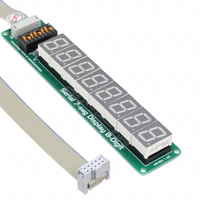
™ Serial 7-Seg Display 8-Digit Manual All Mikroelektronika’s development systems feature a large number of peripheral modules expanding microcontroller’s range of application and making the process of program testing easier. In addition to these modules, it is also possible to use numerous additional modules linked to the development system through the I/O port connectors. Some of these additional modules can operate d as stand-alone devices without being connected to the microcontroller. r a o B l a n o i t i d d A MikroElektronika
2 Serial 7-Seg Display 8-Digit Additional Board The Serial 7-Seg Display 8-Digit additional board features eight 7-segment displays used to display digits. Connection between the additional board and a development system is established via an IDC10 connector on the board and a 2x5 connector on one of the developmet system’s ports. Communication between the additional board and a microcontroller is performed via a Serial Peripheral Interface (SPI), whereas eight 7-segment displays on the additional board are used to display digits. When connecting the board to a development system, it is necessary to set the appropriate switches on the DIP switch SW1 to the ON position. In case EasyPIC, LV18F, EasyLV-18F, Easy24-33 and BigPIC development systems are used, the following switches on the DIP switch SW1 should be set to the ON position: Switch 1 - MOSI Switch 4 - SCK For EasyAVR and Easy8051 development systems, the following switches on the DIP switch SW1 should be set to the ON position: Switch 3 - MOSI Switch 6 - SCK For the EASYdsPIC development system, the following switches on the DIP switch SW1 should be set to the ON position: Switch 2 - MOSI Switch 5 - SCK Switches 7 and 8 on the DIP switch SW1 can also be used for connecting the CS pin (Chip Select) on the additional board to a development system. Depending on the development system in use, CS lines will be connected to different I/O port pins. Accordingly, it is necessary to define in the program, to be loaded into the microcontroller, which pins will be used as the CS pin (Chip Select). IDC10 connector used to connect a development system Figure 1: Serial 7-Seg Display 8-Digit additional board Displaying digits is enabled by the time-division multiplexing. All the operations related to multiplexing and displaying digits are performed by using the MAX7219 circuit provided on the additional board. The time-division multiplexing of a 7-segment display is based on fast turning the display segments on/off in such a manner that one gets impression that all eight digits are active at the same time. The MAX7219 circuit feeds digit segments with a signal via pins marked SEGxx, whereas pins marked DIGx are used to select one of eight displays to show the appropriate number. MikroElektronika
3 Figure 2: Serial 7-Seg Display 8-Digit additional board connection schematic Figure 3: Serial 7-Seg Display 8-Digit additional board connected to a development system MikroElektronika
4 Figure 4: Time-division multiplexing performed on the DIS7 display In Figure 4, signals provided by the MAX7219 circuit causes segments of the DIS7 display to show number 5. When this display turns off, the MAX7219 circuit sends a signal to the next display (DIS6), via the DIG6 pin, to show number 6. The same applies to digits DIS5, DIS4, DIS3, DIS2, DIS1 and DIS0. When one cycle is complete, another one automatically starts, which results in successive changing of display digits DIS7, DIS6, DIS5, DIS4 etc. Figure 5: Principle of time-multiplexing performed on the DIS6 display MikroElektronika
5 MikroElektronika
6 at et k c r ti u o y e m c a o e pl oe.c s r a k e mi pl @ n, e o c rmati at offi m nfo us co al i ct e. n a o o nt bsite at www.mikr or just need additi not hesitate to co our we oducts als, do sit pr os e vi our rop as of s p ple ny es oducts, s with a or busin pr m s ur ble ent o o m ut pr m bo me rt co e a soppo ns, or g u o arn m encinm/en/s questi want to le are experimikroe.co have any ou ou w. ou y yw y If If w If MikroElektronika