ICGOO在线商城 > 集成电路(IC) > PMIC - LED 驱动器 > MIC4802YME
/MIC4802YME.jpg)
 Datasheet下载
- 型号: MIC4802YME
- 制造商: Micrel
- 库位|库存: xxxx|xxxx
- 要求:
| 数量阶梯 | 香港交货 | 国内含税 |
| +xxxx | $xxxx | ¥xxxx |
查看当月历史价格
查看今年历史价格
MIC4802YME产品简介:
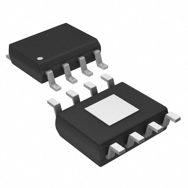
ICGOO电子元器件商城为您提供MIC4802YME由Micrel设计生产,在icgoo商城现货销售,并且可以通过原厂、代理商等渠道进行代购。 MIC4802YME价格参考。MicrelMIC4802YME封装/规格:PMIC - LED 驱动器, LED 驱动器 IC 1 输出 线性 PWM 调光 800mA 8-SOIC-EP。您可以下载MIC4802YME参考资料、Datasheet数据手册功能说明书,资料中有MIC4802YME 详细功能的应用电路图电压和使用方法及教程。
Microchip Technology的PMIC - LED驱动器型号MIC4802YME是一款专为驱动LED而设计的高性能、低功耗集成电路。其应用场景主要包括以下几个方面:

1. 背光显示:MIC4802YME常用于液晶显示屏(LCD)的背光驱动,适用于手机、平板电脑、笔记本电脑和工业显示器等设备。它能够提供稳定的电流输出,确保LED背光的亮度均匀且高效。

2. 汽车照明:该芯片适合应用于汽车内部和外部照明系统,如仪表盘背光、车内氛围灯、刹车灯、转向灯以及日间行车灯(DRL)。其高效率和可靠性使其能够在严苛的汽车环境中稳定工作。

3. 便携式电子设备:MIC4802YME可用于便携式设备(如数码相机、GPS导航仪、可穿戴设备等)中的LED指示灯或背光模块,支持小型化和低功耗设计。

4. 消费类电子产品:在电视、显示器和其他家用电器中,这款驱动器可以用来控制LED指示灯或装饰灯,提供多种调光模式以满足用户需求。

5. 工业与商业应用:例如信号标志、广告牌、状态指示灯等领域,MIC4802YME能够实现精确的电流调节,适应不同亮度要求。

6. 通用LED照明:虽然主要针对中小功率LED应用,但也可用于某些特定场合下的室内或室外照明解决方案。

总之,MIC4802YME凭借其小巧封装、高效能转换比及灵活配置选项,在需要精准电流控制和小型化设计的各种LED驱动场景中表现出色。
| 参数 | 数值 |
| 产品目录 | 集成电路 (IC)光电子产品 |
| 描述 | IC WHITE LED DVR 800MA 1CH 8SOICLED照明驱动器 800mA Single Channel WLED Driver w/ Ultrafast PWM Control |
| 产品分类 | |
| 品牌 | Micrel |
| 产品手册 | |
| 产品图片 |
|
| rohs | 符合RoHS无铅 / 符合限制有害物质指令(RoHS)规范要求 |
| 产品系列 | LED照明电子器件,LED照明驱动器,Micrel MIC4802YME- |
| 数据手册 | |
| 产品型号 | MIC4802YME |
| PCN组件/产地 | |
| 产品种类 | LED照明驱动器 |
| 供应商器件封装 | 8-SOIC-EP |
| 其它名称 | 576-3857-5 |
| 内部驱动器 | 是 |
| 包装 | 管件 |
| 商标 | Micrel |
| 安装类型 | 表面贴装 |
| 安装风格 | SMD/SMT |
| 封装 | Tube |
| 封装/外壳 | 8-SOIC(0.154",3.90mm 宽)裸焊盘 |
| 封装/箱体 | SOIC-8 |
| 工作温度 | -40°C ~ 125°C |
| 工厂包装数量 | 95 |
| 恒压 | - |
| 恒流 | 是 |
| 拓扑 | 线性(LDO),低端,PWM |
| 最大工作温度 | + 125 C |
| 最大电源电流 | 800 mA |
| 最小工作温度 | - 40 C |
| 标准包装 | 95 |
| 电压-电源 | 3 V ~ 5.5 V |
| 电压-输出 | - |
| 类型-初级 | 通用 |
| 类型-次级 | 白色 LED |
| 系列 | MIC4802 |
| 输入电压 | 3 V to 5.5 V |
| 输出数 | 1 |
| 频率 | - |


- 商务部:美国ITC正式对集成电路等产品启动337调查
- 曝三星4nm工艺存在良率问题 高通将骁龙8 Gen1或转产台积电
- 太阳诱电将投资9.5亿元在常州建新厂生产MLCC 预计2023年完工
- 英特尔发布欧洲新工厂建设计划 深化IDM 2.0 战略
- 台积电先进制程称霸业界 有大客户加持明年业绩稳了
- 达到5530亿美元!SIA预计今年全球半导体销售额将创下新高
- 英特尔拟将自动驾驶子公司Mobileye上市 估值或超500亿美元
- 三星加码芯片和SET,合并消费电子和移动部门,撤换高东真等 CEO
- 三星电子宣布重大人事变动 还合并消费电子和移动部门
- 海关总署:前11个月进口集成电路产品价值2.52万亿元 增长14.8%


PDF Datasheet 数据手册内容提取
MIC4802 High Efficiency 800mA Single Channel Linear WLED Driver with Ultra Fast PWM™ Control General Description Features The MIC4802 is a high efficiency White LED (WLED) • High Efficiency (no Voltage Boost losses) driver designed to drive a single LED up to 800mA. The • Ultra Fast PWM™ control (200Hz to 500kHz) MIC4802 constant current driver is designed to drive high • Input voltage range: 3.0V to 5.5V power LED’s in various lighting applications. The MIC4802 provides the highest possible efficiency as this architecture • Dropout of 280mV at 800mA has no switching losses present in traditional charge • Programmable LED current with external resistor pumps or inductive boost circuits. It features a typical • Current accuracy of ±1% typical dropout of 280mV at 800mA. This allows the LEDs to be driven directly from the voltage source eliminating Applications switching noise/losses present with the use of boost • Bill board displays circuitry. The high accuracy (±1% Typical) current regulated WLED channel ensures uniform display • Marquee displays illumination under all conditions. The brightness is • Instrument displays controlled through an Ultra Fast PWM™ Control interface • Architectural lighting operating down to less than 1% duty cycle. The MIC4802 is available in the 8-pin SOIC Epad package with a junction temperature range of -40°C to +125°C. Datasheets and support documentation can be found on Micrel’s web site at: www.micrel.com. ____________________________________________________________________________________________________________ Typical Application High Current Lighting Schematic Ultra Fast PWM is a trademark of Micrel, Inc. Micrel Inc. • 2180 Fortune Drive • San Jose, CA 95131 • USA • tel +1 (408) 944-0800 • fax + 1 (408) 474-1000 • http://www.micrel.com January 2011 M9999-013111-B
Micrel Inc. MIC4802 Ordering Information Part Number Temperature Range Package MIC4802YME –40°C to +125°C 8-Pin EPAD SOIC Pin Configuration 8-Pin Epad SOIC (ME) (Top View) Pin Description Pin Number Pin Name Pin Function 1 VIN Voltage Input. Connect at least 2.2µF ceramic capacitor between VIN and GND. 2 EN Enable LED drivers. This pin can be used as a PWM input for dimming of WLEDs. Do not leave floating. 3 RSET An internal 1.27V reference sets the nominal maximum WLED current. Example, apply a 6.19kΩ resistor between RSET and GND to set LED current to 830mA at 100% duty cycle. 4 GND Ground. 5 D1 LED1 driver input. Connect LED anode to VIN and cathode to this pin. All D1 pins must be connected to the LED. 6 D1 LED1 driver input. Connect LED anode to VIN and cathode to this pin. All D1 pins must be connected to the LED. 7 D1 LED1 driver input. Connect LED anode to VIN and cathode to this pin. All D1 pins must be connected to the LED. 8 D1 LED1 driver input. Connect LED anode to VIN and cathode to this pin. All D1 pins must be connected to the LED. EPAD HS PAD Heat sink pad. Not internally connected. Connect to ground. January 2011 2 M9999-013111-B
Micrel Inc. MIC4802 Absolute Maximum Ratings(1) Operating Ratings(2) Main Input Voltage (V )..................................–0.3V to +6V Supply Voltage (V ).....................................+3.0V to +5.5V IN IN Enable Input Voltage (V )..............................–0.3V to +6V Enable Input Voltage (V ) ....................................0V to V EN EN IN LED Driver Voltage (V ) ................................–0.3V to +6V LED Driver Voltage (V ) .......................................0V to V D1 D1 IN Power Dissipation.....................................Internally Limited Junction Temperature (T )........................–40°C to +125°C J Lead Temperature (soldering, 10sec.).......................260°C Junction Thermal Resistance Storage Temperature (T ).........................–65°C to +150°C EPAD SOIC-8L (θ )..........................................41°C/W s JA Electrical Characteristics V = V = 5V, R = 6.19kΩ; V = 1.2V; T = 25°C, bold values indicate –40°C ≤ T ≤ 125°C; unless noted. IN EN SET D1 J J Parameter Conditions Min Typ Max Units Current Accuracy(3) 747 830 913 mA Drop-out Where I = 90% of LED current seen at LED 280 500 mV V = 1.2V, 100% brightness level DROPNOM Ground/Supply Bias Current I = 830mA 4.1 5.7 mA OUT Shutdown Current V = 0V 0.01 1 µA EN PWM Dimming Enable Input Voltage (V ) Logic Low 0.2 V EN Logic High 1.2 V Enable Input Current V > 1.2V 0.01 1 µA IH Current Source Delay Shutdown to on 40 60 µs (50% levels) Standby to on 2 µs On to Standby 0.3 µs Current Source Transient Time T 1 µs RISE (10%-90%) T 0.3 µs FALL Stand-by to Shutdown Time V = 0V 10 20 40 ms EN Notes: 1. Exceeding the absolute maximum rating may damage the device. 2. The device is not guaranteed to function outside its operating rating. 3. As determined by average current based on R resistance. SET January 2011 3 M9999-013111-B
Micrel Inc. MIC4802 Typical Characteristics Dropout Voltage LED Battery Voltage LED Current vs. LED Current vs. LED Current vs. LED Anode Voltage 1.4 1 500 1.2 VIN = 5.5V 00..89 VIN = 5.5V mV) 440500 LED CURRENT (A) 000...4681 VVINI N= = 3 3.5.0VV LED CURRENT (A) 00000.....34567 VINV IN= 3=. 53V.0V POUT VOLTAGE ( 122335050500000 0.2 O R 100 0.2 0.1 D 50 VIN = 5V 0 0 5.5 5 4.5 4 3.5 3 2.5 5.5 5 4.5 4 3.5 3 2.5 0 0 200 400 600 800 100012001400 LED BATTERY VOLTAGE (V) LED ANODE VOLTAGE (V) LED CURRENT (mA) Supply Bias Current Peak LED Current LED Current vs. LED Anode Voltage vs. R vs. PWM Duty Cycle SET 8 10000 900 upply Bias Current (mA) 234567 VIN = 2.5V VIN = V3I.N5 V= 5.5V ILED (mA) 101001000 LED CURRENT (mA) 234567800000000000000 VINfP =W M5V = 5kHzfPWM =f P1WkMH z= 10kHz S 1 RSET = 4.64kΩ 100 0 1 0 5.5 5 4.5 4 3.5 3 2.5 1 10 100 1000 10000 0 20 40 60 80 100 LED BATTERY VOLTAGE (V) RSET (kΩ) DUTY CYCLE (%) LED Current RSET Voltage Typical I vs. V vs. PWM Duty Cycle vs. LED Current LED LED 900 1.4 2 VIN = 5.0V 1.8 800 fPWM = 20kHz 1.38 1.6 T (mA) 670000 fPWM = 100kHz GE (V) 11..3346 NT (A) 11..24 REN 500 LTA 1.32 RRE 1 UR 400 fPWM = 200kHz VO CU 0.8 LED C 230000 RSET 1.12.83 LED 00..46 100 fPWM = 500kHz 1.26 VIN = 5V 0.2 0 1.24 0 0 20 40 60 80 100 0 200 400 600 800 100012001400 2.4 2.6 2.8 3 3.2 3.4 3.6 DUTY CYCLE (%) LED CURRENT (mA) LED FORWARD VOLTAGE (V) January 2011 4 M9999-013111-B
Micrel Inc. MIC4802 Functional Characteristics January 2011 5 M9999-013111-B
Micrel Inc. MIC4802 Functional Diagram Figure 1. MIC4802 Functional Block Diagram Functional Description Block Diagram As shown in Figure 1, the MIC4802 consists of current The MIC4802 is a single channel linear LED driver with a mirrors set to copy a master current determined by R . maximum 800mA current capability. The LED driver is SET The linear LED drivers have a designated control block designed to maintain proper current regulation with LED for enabling and dimming of the LEDs. The MIC4802 current accuracy of ±10%. The dropout is 280mV at dimming is controlled by the Ultra Fast PWMTM control 800mA. The low dropout of the linear drivers allows the block that receives PWM signals for dimming. LEDs to be driven directly from the battery voltage and eliminates the need for boost or large and inefficient charge pumps. The maximum LED current for each channel is set via an external resistor. Dimming is controlled by applying a PWM signal to the EN pin. The MIC4802 accommodates a wide PWM frequency range as outlined in the application information section. January 2011 6 M9999-013111-B
Micrel Inc. MIC4802 VIN Peak LED Current The input supply (V ) provides power to the linear LED IN vs. R drivers and the control circuitry. The V operating range SET IN 1000 is 3V to 5.5V. A minimum bypass capacitor of 1µF should be placed close to the input (VIN) pin and the ground (GND) pin. Refer to the layout recommendations section for details on placing the input capacitor (C1). A) 100 m EN ED ( L I The EN pin is equivalent to the enable pin for the linear 10 drivers on the MIC4802. It can also be used for dimming applying a PWM signal. See the PWM Dimming Interface in the Application Information section for 1 details. Pulling the EN low for more than 40ms puts the 1 10 100 1000 10000 MIC4802 into a low IQ sleep mode. The EN pin cannot be RSET (kΩ) left floating; a floating enable pin may cause an indeterminate state on the outputs. The first pulse on the EN Figure 2. Peak LED Current vs. R SET pin must be equal or greater than 60µs to wake the part up in a known state. This equates to an 8.3kHz PWM signal at D1 equal or greater than 50% duty cycle. Higher PWM frequencies may be used but the first pulse must be equal or The D1 pins are the linear driver inputs for the LED. greater than 60µs. Connect the anode of the LED to VIN and the cathode to the D1 pins. All the D1 pins must be connected together. RSET The D1 voltage at dropout is the minimum voltage The R pin is used to set the peak current of the linear required by the linear driver in order for the LED to be SET driver by connecting a R resistor to ground. The fully biased. SET theoretical average LED current can be estimated by GND equation (1): The ground pin is the ground path for the linear driver. I (mA) = 4920 * D / R (kΩ) (1) LED SET The ground of the input capacitor should be routed with R (kΩ) = 4920 * D / I (mA) (2) SET LED low impedance traces to the GND pin and made as short as possible. Refer to the layout recommendations for D is the duty cycle of the LED current during PWM more details. dimming. When the device is fully ON the duty cycle equals 100% (D = 1). A plot of I versus R is shown LED SET in Figure 2. Due to DC losses across current paths internal and external to the package, the calculated R resistance SET equation is modified by a factor K, where K is calculated to be 0.280kΩ. R (kΩ) = 4920 * D / I (mA) + 0.280 (kΩ) (3) SET LED I (mA) = 4920 * D / ((R (kΩ) – 0.280 (kΩ)) (4) LED SET The modified LED current equation is more accurate in determining the actual LED current based on the RSET resistor value. January 2011 7 M9999-013111-B
Micrel Inc. MIC4802 Application Information LED Current vs. PWM Duty Cycle Ultra Fast PWM™ Dimming Interface 900 The MIC4802 supports a wide range of PWM control 800 signal frequencies from 200Hz to 500kHz. This fPWM = 20kHz 700 extremely wide range of control provides ultimate A) flexibility for handheld applications using high frequency T (m 600 fPWM = 100kHz PWM control signals. EN 500 R WLED dimming is achieved by applying a pulse width UR 400 fPWM= 200kHz C modulated (PWM) signal to the END pin. For PWM D 300 E frequencies between 200Hz – 10kHz the MIC4802 L 200 supports a duty cycle range from 1% to 100%, as shown in Figure 3. The MIC4802 incorporates an internal 100 fPWM = 500kHz 0 shutdown delay to ensure that the internal control 0 20 40 60 80 100 circuitry remains active during PWM dimming. This DUTY CYCLE (%) feature prevents the possibility of backlight flickering when using low frequency PWM control signals. The Figure 4. Channel Current Response to PWM Control MIC4802 also supports Ultra Fast PWM™ frequencies Signal Frequencies from 50kHz to 500kHz from 20kHz to 500kHz. Due to input signal propagation delay, PWM frequencies above 20kHz have a non-linear Minimum Duty Cycle relationship between the duty cycle and the average vs. Frequency LED current, as shown in Figure 4 and 5. Figures 6 35 through 9 show the WLED current response when a PWM signal is applied to the END pin (1). 30 (1) From the low IQ sleep mode higher PWM frequencies above 15kHz %) 25 require a logic high enable signal for 60μs to first enable the MIC4802 Y ( T prior to PWM dimming. U 20 D M MU 15 NI MI 10 LED Current 5 vs. PWM Duty Cycle 900 0 VIN = 5V 100 1000 10000 100000 1000000 800 fPWM = 1kHz FREQUENCY (Hz) A) 700 m T ( 600 Figure 5. Minimum Duty Cycle EN 500 fPWM = 5kHz for Varying PWM Frequency R R 400 U C D 300 E L 200 fPWM = 10kHz 100 0 0 20 40 60 80 100 DUTY CYCLE (%) Figure 3. Average Current per LED Dimming by Changing PWM Duty Cycle for PWM Frequencies up to 20kHz Figure 6. PWM Signal at 1% Duty Cycle (I = 8mA) avg January 2011 8 M9999-013111-B
Micrel Inc. MIC4802 Thermal Consideration The MIC4802 thermal considerations involve calculating the junction temperature based on the voltage drop across the package and the LED current. The voltage drop across the package is equal to the voltage at D1 with respect to ground times the LED current. P = I * V LOSS LED D1 The temperature rise (ΔT) is calculated: ΔT = P * θ LOSS JA Assuming the I is 800mA and VD1 is 500mV at 20°C LED room temperature, we can calculate the junction temperature: T = T + ΔT J A T = 20°C + 0.4W * 41°C/W Figure 7. PWM Signal at 20% Duty Cycle (I = 160mA) J avg T = 20°C + 16.4°C = 36.4°C J The junction temperature will be 36.4°C. Figure 8. PWM Signal at 50% Duty Cycle (I = 400mA) avg Figure 9. PWM Signal at 80% Duty Cycle (I = 640mA) avg January 2011 9 M9999-013111-B
Micrel Inc. MIC4802 MIC4802 Typical Application Circuit Bill of Materials Item Part Number Manufacturer Description Qty. C1608X5R0J225K TDK(1) 06036D225KAT2A AVX(2) C1 Ceramic Capacitor, 2.2µF, 6.3V, X5R, Size 0603 1 GRM188R60J225KE19D Murata(3) VJ0603G225KXYAT Vishay(4) LED R42180 Seoul Semiconductor(5) 3.8W High Power WLED 1 R CRCW06036K19FKEA Vishay(4) Resistor, 6.19kΩ, 1%, 1/16W, Size 0603 1 SET 800mA Single Channel Ultra Fast PWM™ U1 MIC4802YME Micrel, Inc.(6) 1 Linear WLED Driver Notes: 1. TDK: www.tdk.com 2. AVX: www.avx.com 3. Murata: www.murata.com 4. Vishay: www.vishay.com 5. Seoul Semi: http://www.acriche.com/en 6. Micrel, Inc.: www.micrel.com January 2011 10 M9999-013111-B
Micrel Inc. MIC4802 Layout Recommendations Top Layer Bottom Layer January 2011 11 M9999-013111-B
Micrel Inc. MIC4802 Package Information 8-Pin SOIC (ME) MICREL, INC. 2180 FORTUNE DRIVE SAN JOSE, CA 95131 USA TEL +1 (408) 944-0800 FAX +1 (408) 474-1000 WEB http://www.micrel.com Micrel makes no representations or warranties with respect to the accuracy or completeness of the information furnished in this data sheet. This information is not intended as a warranty and Micrel does not assume responsibility for its use. Micrel reserves the right to change circuitry, specifications and descriptions at any time without notice. No license, whether express, implied, arising by estoppel or otherwise, to any intellectual property rights is granted by this document. Except as provided in Micrel’s terms and conditions of sale for such products, Micrel assumes no liability whatsoever, and Micrel disclaims any express or implied warranty relating to the sale and/or use of Micrel products including liability or warranties relating to fitness for a particular purpose, merchantability, or infringement of any patent, copyright or other intellectual property right. Micrel Products are not designed or authorized for use as components in life support appliances, devices or systems where malfunction of a product can reasonably be expected to result in personal injury. Life support devices or systems are devices or systems that (a) are intended for surgical implant into the body or (b) support or sustain life, and whose failure to perform can be reasonably expected to result in a significant injury to the user. A Purchaser’s use or sale of Micrel Products for use in life support appliances, devices or systems is a Purchaser’s own risk and Purchaser agrees to fully indemnify Micrel for any damages resulting from such use or sale. © 2010 Micrel, Incorporated. January 2011 12 M9999-013111-B
Mouser Electronics Authorized Distributor Click to View Pricing, Inventory, Delivery & Lifecycle Information: M icrochip: MIC4802YME MIC4802YME-TR