ICGOO在线商城 > 集成电路(IC) > PMIC - 栅极驱动器 > MIC4420YM
/MIC4420YM.jpg)
 Datasheet下载
- 型号: MIC4420YM
- 制造商: Micrel
- 库位|库存: xxxx|xxxx
- 要求:
| 数量阶梯 | 香港交货 | 国内含税 |
| +xxxx | $xxxx | ¥xxxx |
查看当月历史价格
查看今年历史价格
MIC4420YM产品简介:
ICGOO电子元器件商城为您提供MIC4420YM由Micrel设计生产,在icgoo商城现货销售,并且可以通过原厂、代理商等渠道进行代购。 MIC4420YM价格参考¥8.99-¥8.99。MicrelMIC4420YM封装/规格:PMIC - 栅极驱动器, Low-Side Gate Driver IC Non-Inverting 8-SOIC。您可以下载MIC4420YM参考资料、Datasheet数据手册功能说明书,资料中有MIC4420YM 详细功能的应用电路图电压和使用方法及教程。
Microchip Technology的MIC4420YM是一款PMIC(电源管理集成电路)栅极驱动器,广泛应用于需要高效驱动功率MOSFET或IGBT的应用场景中。以下是该型号的一些主要应用场景:

1. 电机驱动:在工业自动化和消费电子领域,电机驱动系统需要高效率和快速响应的栅极驱动器。MIC4420YM可以为这些系统的功率级提供可靠的驱动信号,确保电机运行稳定、高效。

2. 电源转换:在开关电源(SMPS)、DC-DC转换器等电源管理系统中,MIC4420YM能够精确控制功率MOSFET或IGBT的开关状态,提高转换效率,减少能量损失。它适用于各种电压和电流等级的电源设计。

3. 太阳能逆变器:在可再生能源领域,如太阳能逆变器中,MIC4420YM可以用于驱动逆变器中的功率器件,实现高效的直流到交流转换,提升系统的整体性能和可靠性。

4. 电动汽车(EV)和混合动力汽车(HEV):在电动汽车和混合动力汽车的动力系统中,MIC4420YM可用于驱动车载充电器、逆变器和DC-DC转换器中的功率器件,确保车辆的电气系统高效运行。

5. 不间断电源(UPS):在UPS系统中,MIC4420YM可以用于驱动逆变器和电池充电电路中的功率器件,保证在市电中断时能够迅速切换到备用电源,并保持稳定的输出。

6. 家电产品:在一些高端家电产品中,如空调、洗衣机等,MIC4420YM可以用于驱动压缩机或其他大功率负载,提高产品的能效比,延长使用寿命。

7. 通信设备:在基站、路由器等通信设备中,MIC4420YM可以用于驱动电源模块中的功率器件,确保设备在高负荷下稳定运行,同时降低功耗。

总之,MIC4420YM凭借其高效、可靠的特点,在多个行业中都有广泛应用,尤其适合需要高精度和快速响应的功率控制应用。
| 参数 | 数值 |
| 产品目录 | 集成电路 (IC)半导体 |
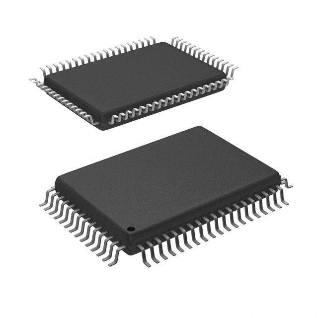
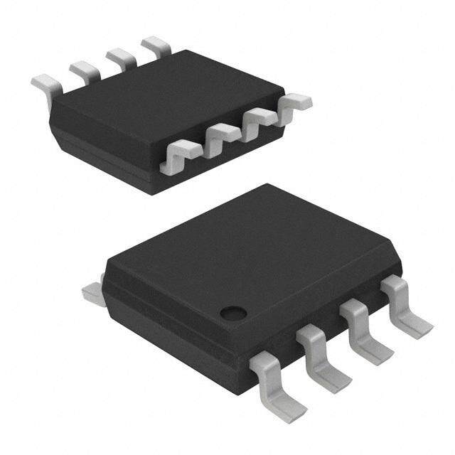
| 描述 | IC DRIVER MOSFET 6A LS 8-SOIC门驱动器 6A Hi-Speed, Hi-Current Single MOSFET Driver (Lead Free) |
| 产品分类 | PMIC - MOSFET,电桥驱动器 - 外部开关集成电路 - IC |
| 品牌 | Micrel |
| 产品手册 | |
| 产品图片 |
|
| rohs | 符合RoHS无铅 / 符合限制有害物质指令(RoHS)规范要求 |
| 产品系列 | 电源管理 IC,门驱动器,Micrel MIC4420YM- |
| 数据手册 | |
| 产品型号 | MIC4420YM |
| 上升时间 | 25 ns |
| 下降时间 | 25 ns |
| 产品 | MOSFET Gate Drivers |
| 产品目录页面 | |
| 产品种类 | 门驱动器 |
| 供应商器件封装 | 8-SOIC |
| 其它名称 | 576-3376-5 |
| 包装 | 管件 |
| 商标 | Micrel |
| 安装类型 | 表面贴装 |
| 安装风格 | SMD/SMT |
| 封装 | Tube |
| 封装/外壳 | 8-SOIC(0.154",3.90mm 宽) |
| 封装/箱体 | SOIC-8 |
| 工作温度 | -40°C ~ 85°C |
| 工厂包装数量 | 95 |
| 延迟时间 | 18ns |
| 最大关闭延迟时间 | 18 ns |
| 最大功率耗散 | 1040 mW |
| 最大工作温度 | + 85 C |
| 最大开启延迟时间 | 18 ns |
| 最小工作温度 | - 40 C |
| 标准包装 | 95 |
| 电压-电源 | 4.5 V ~ 18 V |
| 电流-峰值 | 6A |
| 电源电压-最大 | 18 V |
| 电源电压-最小 | 4.5 V |
| 电源电流 | 450 uA |
| 类型 | Low Side |
| 系列 | MIC4420 |
| 输入类型 | 非反相 |
| 输出数 | 1 |
| 输出电压 | 25 mV |
| 输出电流 | 6 A |
| 输出端数量 | 1 |
| 配置 | Non-Inverting |
| 配置数 | 1 |
| 高压侧电压-最大值(自举) | - |


- 商务部:美国ITC正式对集成电路等产品启动337调查
- 曝三星4nm工艺存在良率问题 高通将骁龙8 Gen1或转产台积电
- 太阳诱电将投资9.5亿元在常州建新厂生产MLCC 预计2023年完工
- 英特尔发布欧洲新工厂建设计划 深化IDM 2.0 战略
- 台积电先进制程称霸业界 有大客户加持明年业绩稳了
- 达到5530亿美元!SIA预计今年全球半导体销售额将创下新高
- 英特尔拟将自动驾驶子公司Mobileye上市 估值或超500亿美元
- 三星加码芯片和SET,合并消费电子和移动部门,撤换高东真等 CEO
- 三星电子宣布重大人事变动 还合并消费电子和移动部门
- 海关总署:前11个月进口集成电路产品价值2.52万亿元 增长14.8%


PDF Datasheet 数据手册内容提取
MIC4420/4429 Micrel, Inc. MIC4420/4429 6A-Peak Low-Side MOSFET Driver Bipolar/CMOS/DMOS Process General Description Features • CMOS Construction MIC4420, MIC4429 and MIC429 MOSFET drivers are • Latch-Up Protected: Will Withstand >500mA tough, efficient, and easy to use. The MIC4429 and MIC429 Reverse Output Current are inverting drivers, while the MIC4420 is a non-inverting • Logic Input Withstands Negative Swing of Up to 5V driver. • Matched Rise and Fall Times ................................25ns They are capable of 6A (peak) output and can drive the larg- • High Peak Output Current ...............................6A Peak est MOSFETs with an improved safe operating margin. The • Wide Operating Range ...............................4.5V to 18V MIC4420/4429/429 accepts any logic input from 2.4V to V • High Capacitive Load Drive ............................10,000pF S without external speed-up capacitors or resistor networks. • Low Delay Time ..............................................55ns Typ Proprietary circuits allow the input to swing negative by as • Logic High Input for Any Voltage From 2.4V to V S much as 5V without damaging the part. Additional circuits • Low Equivalent Input Capacitance (typ) ..................6pF protect against damage from electrostatic discharge. • Low Supply Current ...............450µA With Logic 1 Input • Low Output Impedance .........................................2.5Ω MIC4420/4429/429 drivers can replace three or more • Output Voltage Swing Within 25mV of Ground or V discrete components, reducing PCB area requirements, S simplifying product design, and reducing assembly cost. Applications Modern BiCMOS/DMOS construction guarantees freedom • Switch Mode Power Supplies from latch-up. The rail-to-rail swing capability insures ad- • Motor Controls equate gate voltage to the MOSFET during power up/down • Pulse Transformer Driver sequencing. • Class-D Switching Amplifiers Note: See MIC4120/4129 for high power and narrow pulse applications. Functional Diagram V S MIC4429 0.4mA INVERTING 0.1mA OUT IN 2kΩ MIC4420 NONINVERTING GND Micrel, Inc. • 2180 Fortune Drive • San Jose, CA 95131 • USA • tel + 1 (408) 944-0800 • fax + 1 (408) 474-1000 • http://www.micrel.com July 2005 1 M9999-072205
MIC4420/4429 Micrel, Inc. Ordering Information Part No. Temperature Standard Pb-Free Range Package Configuration MIC4420CN MIC4420ZN 0°C to +70°C 8-Pin PDIP Non-Inverting MIC4420BN MIC4420YN –40°C to +85°C 8-Pin PDIP Non-Inverting MIC4420CM MIC4420ZM 0°C to +70°C 8-Pin SOIC Non-Inverting MIC4420BM MIC4420YM –40°C to +85°C 8-Pin SOIC Non-Inverting MIC4420BMM MIC4420YMM –40°C to +85°C 8-Pin MSOP Non-Inverting MIC4420CT MIC4420ZT 0°C to +70°C 5-Pin TO-220 Non-Inverting MIC4429CN MIC4429ZN 0°C to +70°C 8-Pin PDIP Inverting MIC4429BN MIC4429YN –40°C to +85°C 8-Pin PDIP Inverting MIC4429CM MIC4429ZM 0°C to +70°C 8-Pin SOIC Inverting MIC4429BM MIC4429YM –40°C to +85°C 8-Pin SOIC Inverting MIC4429BMM MIC4429YMM –40°C to +85°C 8-Pin MSOP Inverting MIC4429CT MIC4429ZT 0°C to +70°C 5-Pin TO-220 Inverting Pin Configurations VS 1 8 VS IN 2 7 OUT NC 3 6 OUT GND 4 5 GND Plastic DIP (N) SOIC (M) MSOP (MM) 5 OUT 4 GND 3 VS 2 GND 1 IN TO-220-5 (T) Pin Description Pin Number Pin Number Pin Name Pin Function TO-220-5 DIP, SOIC, MSOP 1 2 IN Control Input 2, 4 4, 5 GND Ground: Duplicate pins must be externally connected together. 3, TAB 1, 8 V Supply Input: Duplicate pins must be externally connected together. S 5 6, 7 OUT Output: Duplicate pins must be externally connected together. 3 NC Not connected. M9999-072205 2 July 2005
MIC4420/4429 Micrel, Inc. Absolute Maximum Ratings (Notes 1, 2 and 3) Operating Ratings Supply Voltage ...........................................................20V Supply Voltage ..............................................4.5V to 18V Input Voltage ...............................V + 0.3V to GND – 5V Junction Temperature .............................................150°C S Input Current (V > V ) ..........................................50mA Ambient Temperature IN S Power Dissipation, T ≤ 25°C C Version .................................................0°C to +70°C A PDIP ....................................................................960W B Version .............................................–40°C to +85°C SOIC ...............................................................1040mW Package Thermal Resistance 5-Pin TO-220 ...........................................................2W 5-pin TO-220 (θ ) ............................................10°C/W JC Power Dissipation, T ≤ 25°C 8-pin MSOP (θ ) ...........................................250°C/W C JA 5-Pin TO-220 ......................................................12.5W Derating Factors (to Ambient) PDIP .............................................................7.7mW/°C SOIC .............................................................8.3mW/°C 5-Pin TO-220 .................................................17mW/°C Storage Temperature .............................–65°C to +150°C Lead Temperature (10 sec.) ...................................300°C Electrical Characteristics: (T = 25°C with 4.5V ≤ V ≤ 18V unless otherwise specified. Note 4.) A S Symbol Parameter Conditions Min Typ Max Units INPUT V Logic 1 Input Voltage 2.4 1.4 V IH V Logic 0 Input Voltage 1.1 0.8 V IL V Input Voltage Range –5 V + 0.3 V IN S I Input Current 0 V ≤ V ≤ V –10 10 µA IN IN S OUTPUT V High Output Voltage See Figure 1 V –0.025 V OH S V Low Output Voltage See Figure 1 0.025 V OL R Output Resistance, I = 10 mA, V = 18 V 1.7 2.8 Ω O OUT S Output Low R Output Resistance, I = 10 mA, V = 18 V 1.5 2.5 Ω O OUT S Output High I Peak Output Current V = 18 V (See Figure 6) 6 A PK S I Latch-Up Protection >500 mA R Withstand Reverse Current SWITCHING TIME (Note 3) t Rise Time Test Figure 1, C = 2500 pF 12 35 ns R L t Fall Time Test Figure 1, C = 2500 pF 13 35 ns F L t Delay Time Test Figure 1 18 75 ns D1 t Delay Time Test Figure 1 48 75 ns D2 POWER SUPPLY I Power Supply Current V = 3 V 0.45 1.5 mA S IN V = 0 V 90 150 µA IN V Operating Input Voltage 4.5 18 V S July 2005 3 M9999-072205
MIC4420/4429 Micrel, Inc. Electrical Characteristics: (T = –55°C to +125°C with 4.5V ≤ V ≤ 18V unless otherwise specified.) A S Symbol Parameter Conditions Min Typ Max Units INPUT V Logic 1 Input Voltage 2.4 V IH V Logic 0 Input Voltage 0.8 V IL V Input Voltage Range –5 V + 0.3 V IN S I Input Current 0V ≤ V ≤ V –10 10 µA IN IN S OUTPUT V High Output Voltage Figure 1 V –0.025 V OH S V Low Output Voltage Figure 1 0.025 V OL R Output Resistance, I = 10mA, V = 18V 3 5 Ω O OUT S Output Low R Output Resistance, I = 10mA, V = 18V 2.3 5 Ω O OUT S Output High SWITCHING TIME (Note 3) t Rise Time Figure 1, C = 2500pF 32 60 ns R L t Fall Time Figure 1, C = 2500pF 34 60 ns F L t Delay Time Figure 1 50 100 ns D1 t Delay Time Figure 1 65 100 ns D2 POWER SUPPLY I Power Supply Current V = 3V 0.45 3.0 mA S IN V = 0V 0.06 0.4 mA IN V Operating Input Voltage 4.5 18 V S Note 1: Functional operation above the absolute maximum stress ratings is not implied. Note 2: Static-sensitive device. Store only in conductive containers. Handling personnel and equipment should be grounded to prevent damage from static discharge. Note 3: Switching times guaranteed by design. Note 4: Specification for packaged product only. Test Circuits VS = 18V VS = 18V 0.1µF 0.1µF 1.0µF 0.1µF 0.1µF 1.0µF IN OUT IN OUT 2500pF 2500pF MIC4429 MIC4420 5V 5V 2.5V 2.5V 90% 90% INPUT 10% tPW≥ 0.5µs INPUT 10% tPW≥ 0.5µs 0V 0V tPW tPW VS tD1 tF tD2 tR VS tD1 tR tD2 tF 90% 90% OUTPUT OUTPUT 10% 10% 0V 0V Figure 1. Inverting Driver Switching Time Figure 2. Noninverting Driver Switching Time M9999-072205 4 July 2005
MIC4420/4429 Micrel, Inc. Typical Characteristic Curves RiseTime vs. SupplyVoltage FallTime vs. SupplyVoltage Rise and FallTimes vs.Temperature 60 50 25 C L = 2200 pF V = 18V 50 S 40 20 40 C L = 10,000 pF C L = 10,000 pF s) s) 30 s)15 E (n 30 E (n E (n tFALL TIM C L = 4700 pF TIM 20 C L = 4700 pF TIM10 tRISE 20 C L = 2200 pF C L = 2200 pF 10 5 10 0 0 0 5 7 9 11 13 15 5 7 9 11 13 15 –60 –20 20 60 100 140 VS (V) VS (V) TEMPERATURE (°C) RiseTime vs. Capacitive Load FallTime vs. Capacitive Load DelayTime vs. SupplyVoltage 50 50 60 40 40 50 30 30 tD2 E (ns) 20 VS = 5V E (ns)20 VS = 5V ME (ns)40 M M TI30 TI VS = 12V TI VS = 12V V = 18V AY V = 18V S L S E20 10 10 D tD1 10 5 5 0 1000 3000 10,000 1000 3000 10,000 4 6 8 10 12 14 16 18 CAPACITIVE LOAD (pF) CAPACITIVE LOAD (pF) SUPPLY VOLTAGE (V) Propagation Delay Time vs.Temperature Supply Current vs. Capacitive Load Supply Current vs. Frequency 60 84 1000 VS = 15V CL = 2200 pF 50 tD2 mA)70 A) 18V ns)40 RENT (56 ENT (m 100 150VV E ( UR RR M C42 U TI30 tD1 PPLY 28 500 kHz PLY C 10 U P S U 20 – 200 kHz S C L = 2200 pF I S14 V = 18V 20 kHz 10 S 0 0 –60 –20 20 60 100 140 0 100 1000 10,000 0 100 1000 10,000 TEMPERATURE (°C) CAPACITIVE LOAD (pF) FREQUENCY (kHz) July 2005 5 M9999-072205
MIC4420/4429 Micrel, Inc. Typical Characteristic Curves (Cont.) Quiescent Power Supply Quiescent Power Supply Voltage vs. Supply Current Current vs. Temperature 1000 900 LOGIC “1” INPUT V = 18V S A)800 A)800 T ( T ( N N RRE600 LOGIC “1” INPUT RRE700 U U C C Y 400 Y 600 L L P P P P U U S200 S500 LOGIC “0” INPUT 0 400 0 4 8 12 16 20 –60 –20 20 60 100 140 SUPPLY VOLTAGE (V) TEMPERATURE (°C) High-State Output Resistance Low-State Output Resistance 5 2.5 100 mA 4 2 R ( )WOUT 10 mA 50 mA R ( )WOUT 100 mA50 mA 3 1.5 10 mA 2 1 5 7 9 11 13 15 5 7 9 11 13 15 V (V) V (V) S S Effect of Input Amplitude on Propagation Delay Crossover Area vs. Supply Voltage 200 2.0 LOAD = 2200 pF PER TRANSITION 8 -0 160 1 x 1.5 s) Y (ns)120 INPUT 2.4V EA (A• A R1.0 L INPUT 3.0V A DE 80 ER INPUT 5.0V V O S0.5 40 INPUT 8V AND 10V OS R C 0 0 5 6 7 8 9 10 11 12 13 14 15 5 6 7 8 9 10 11 12 13 14 15 V (V) SUPPLY VOLTAGE V (V) S S M9999-072205 6 July 2005
MIC4420/4429 Micrel, Inc. Applications Information Grounding Supply Bypassing The high current capability of the MIC4420/4429 demands careful PC board layout for best performance Since the Charging and discharging large capacitive loads quickly MIC4429 is an inverting driver, any ground lead impedance requires large currents. For example, charging a 2500pF will appear as negative feedback which can degrade switch- load to 18V in 25ns requires a 1.8 A current from the device ing speed. Feedback is especially noticeable with slow-rise power supply. time inputs. The MIC4429 input structure includes 300mV of hysteresis to ensure clean transitions and freedom from The MIC4420/4429 has double bonding on the supply pins, oscillation, but attention to layout is still recommended. the ground pins and output pins This reduces parasitic lead inductance. Low inductance enables large currents to be Figure 3 shows the feedback effect in detail. As the MIC4429 switched rapidly. It also reduces internal ringing that can input begins to go positive, the output goes negative and cause voltage breakdown when the driver is operated at several amperes of current flow in the ground lead. As little or near the maximum rated voltage. as 0.05Ω of PC trace resistance can produce hundreds of millivolts at the MIC4429 ground pins. If the driving logic is Internal ringing can also cause output oscillation due to referenced to power ground, the effective logic input level feedback. This feedback is added to the input signal since is reduced and oscillation may result. it is referenced to the same ground. To insure optimum performance, separate ground traces To guarantee low supply impedance over a wide frequency should be provided for the logic and power connections. range, a parallel capacitor combination is recommended for Connecting the logic ground directly to the MIC4429 GND supply bypassing. Low inductance ceramic disk capacitors pins will ensure full logic drive to the input and ensure fast with short lead lengths (< 0.5 inch) should be used. A 1µF output switching. Both of the MIC4429 GND pins should, low ESR film capacitor in parallel with two 0.1 µF low ESR however, still be connected to power ground. ceramic capacitors, (such as AVX RAM GUARD®), provides adequate bypassing. Connect one ceramic capacitor di- rectly between pins 1 and 4. Connect the second ceramic capacitor directly between pins 8 and 5. +15 (x2) 1N4448 5.6kΩ 560Ω 0.1µF 50V + 1µF 50V BYV 10 (x 2) 1 MKS2 8 2 6,7 + MIC4429 0.1µF WIMA 5 220 µF 50V + MKS2 4 35 µF 50V UNITED CHEMCON SXE Figure 3. Self-Contained Voltage Doubler July 2005 7 M9999-072205
MIC4420/4429 Micrel, Inc. Input Stage attention should be given to power dissipation when driving low impedance loads and/or operating at high frequency. The input voltage level of the 4429 changes the quiescent supply current. The N channel MOSFET input stage tran- The supply current vs frequency and supply current vs sistor drives a 450µA current source load. With a logic “1” capacitive load characteristic curves aid in determining input, the maximum quiescent supply current is 450µA. power dissipation calculations. Table 1 lists the maximum Logic “0” input level signals reduce quiescent current to safe operating frequency for several power supply volt- 55µA maximum. ages when driving a 2500pF load. More accurate power dissipation figures can be obtained by summing the three The MIC4420/4429 input is designed to provide 300mV of dissipation sources. hysteresis. This provides clean transitions, reduces noise sensitivity, and minimizes output stage current spiking when Given the power dissipation in the device, and the thermal changing states. Input voltage threshold level is approxi- resistance of the package, junction operating temperature mately 1.5V, making the device TTL compatible over the for any ambient is easy to calculate. For example, the 4 .5V to 18V operating supply voltage range. Input current thermal resistance of the 8-pin MSOP package, from the is less than 10µA over this range. data sheet, is 250°C/W. In a 25°C ambient, then, using a maximum junction temperature of 150°C, this package will The MIC4429 can be directly driven by the TL494, dissipate 500mW. SG1526/1527, SG1524, TSC170, MIC38HC42 and similar switch mode power supply integrated circuits. By offloading Accurate power dissipation numbers can be obtained by the power-driving duties to the MIC4420/4429, the power summing the three sources of power dissipation in the supply controller can operate at lower dissipation. This can device: improve performance and reliability. • Load Power Dissipation (P ) L The input can be greater than the +V supply, however, • Quiescent power dissipation (P ) S Q current will flow into the input lead. The propagation delay • Transition power dissipation (P ) T for T will increase to as much as 400ns at room tem- D2 perature. The input currents can be as high as 30mA p-p Calculation of load power dissipation differs depending on (6.4mA ) with the input, 6 V greater than the supply whether the load is capacitive, resistive or inductive. RMS voltage. No damage will occur to MIC4420/4429 however, Resistive Load Power Dissipation and it will not latch. Dissipation caused by a resistive load can be calculated The input appears as a 7pF capacitance, and does not as: change even if the input is driven from an AC source. Care should be taken so that the input does not go more than 5 P = I2 R D L O volts below the negative rail. where: Power Dissipation I = the current drawn by the load CMOS circuits usually permit the user to ignore power dis- R = the output resistance of the driver when the output sipation. Logic families such as 4000 and 74C have outputs O is high, at the power supply voltage used. (See data which can only supply a few milliamperes of current, and sheet) even shorting outputs to ground will not force enough cur- D = fraction of time the load is conducting (duty cycle) rent to destroy the device. The MIC4420/4429 on the other hand, can source or sink several amperes and drive large capacitive loads at high frequency. The package power dissipation limit can easily be exceeded. Therefore, some +18V Table 1: MIC4429 Maximum Operating Frequency WIMA MKS-2 1 µF V Max Frequency S 5.0V 1 TEK CURRENT 18V 18V 500kHz 8 PROBE 6302 6,7 15V 700kHz MIC4429 0V 5 0V 10V 1.6MHz 0.1µF 4 0.1µF 2P,O50L0Y CpFARBONATE Conditions: 1. DIP Package (θJA = 130°C/W) 2. T = 25°C A LOGIC 3. C = 2500pF GROUND 6 AMPS L 300 mV PC TRACE RESISTANCE = 0.05Ω POWER GROUND Figure 4. Switching Time Degradation Due to Negative Feedback M9999-072205 8 July 2005
MIC4420/4429 Micrel, Inc. Capacitive Load Power Dissipation where: Dissipation caused by a capacitive load is simply the en- I = quiescent current with input high H ergy placed in, or removed from, the load capacitance by I = quiescent current with input low L the driver. The energy stored in a capacitor is described D = fraction of time input is high (duty cycle) by the equation: V = power supply voltage S E = 1/2 C V2 Transition Power Dissipation As this energy is lost in the driver each time the load is Transition power is dissipated in the driver each time its charged or discharged, for power dissipation calculations output changes state, because during the transition, for a the 1/2 is removed. This equation also shows that it is very brief interval, both the N- and P-channel MOSFETs in good practice not to place more voltage on the capacitor the output totem-pole are ON simultaneously, and a cur- than is necessary, as dissipation increases as the square rent is conducted through them from V+ to ground. The S of the voltage applied to the capacitor. For a driver with a transition power dissipation is approximately: capacitive load: P = 2 f V (A•s) T S P = f C (V )2 L S where (A•s) is a time-current factor derived from the typical where: characteristic curves. f = O perating Frequency Total power (P ) then, as previously described is: D C = Load Capacitance P = P + P +P V = Driver Supply Voltage D L Q T S Definitions Inductive Load Power Dissipation C = Load Capacitance in Farads. For inductive loads the situation is more complicated. For L the part of the cycle in which the driver is actively forcing D = Duty Cycle expressed as the fraction of time the current into the inductor, the situation is the same as it is input to the driver is high. in the resistive case: f = Operating Frequency of the driver in Hertz P = I2 R D L1 O I = Power supply current drawn by a driver when both However, in this instance the R required may be either H O inputs are high and neither output is loaded. the on resistance of the driver when its output is in the high state, or its on resistance when the driver is in the low state, I = Power supply current drawn by a driver when both L depending on how the inductor is connected, and this is inputs are low and neither output is loaded. still only half the story. For the part of the cycle when the I = Output current from a driver in Amps. inductor is forcing current through the driver, dissipation is D best described as P = Total power dissipated in a driver in Watts. D PL2 = I VD (1-D) PL = Power dissipated in the driver due to the driver’s load in Watts. where V is the forward drop of the clamp diode in the D driver (generally around 0.7V). The two parts of the load P = Power dissipated in a quiescent driver in Q dissipation must be summed in to produce PL Watts. PL = PL1 + PL2 PT = Power dissipated in a driver when the output changes states (“shoot-through current”) in Watts. Quiescent Power Dissipation NOTE: The “shoot-through” current from a dual Quiescent power dissipation (P , as described in the input transition (once up, once down) for both drivers Q section) depends on whether the input is high or low. A low is shown by the "Typical Characteristic Curve : input will result in a maximum current drain (per driver) of Crossover Area vs. Supply Voltage and is in am- ≤0.2mA; a logic high will result in a current drain of ≤2.0mA. pere-seconds. This figure must be multiplied by Quiescent power can therefore be found from: the number of repetitions per second (frequency) to find Watts. P = V [D I + (1-D) I ] Q S H L R = Output resistance of a driver in Ohms. O V = Power supply voltage to the IC in Volts. S July 2005 9 M9999-072205
MIC4420/4429 Micrel, Inc. +18 V WIMA MK22 1 µF 5.0V 18 V 1 TEK CURRENT 8 PROBE 6302 2 6,7 MIC4429 0 V 5 0 V 0.1µF 0.1µF 4 10,000 pF POLYCARBONATE Figure 5. Peak Output Current Test Circuit M9999-072205 10 July 2005
MIC4420/4429 Micrel, Inc. Package Information PIN 1 DIMENSIONS: INCH (MM) 0.380 (9.65) 0.255 (6.48) 0.370 (9.40) 0.135 (3.43) 0.245 (6.22) 0.125 (3.18) 0.300 (7.62) 0.013 (0.330) 0.010 (0.254) 0.018 (0.57) 0.130 (3.30) 0.380 (9.65) 0.320 (8.13) 0.100 (2.54) 0.0375 (0.952) 8-Pin Plastic DIP (N) 8-Pin SOIC (M) July 2005 11 M9999-072205
MIC4420/4429 Micrel, Inc. 0.112 (2.84) 0.187 (4.74) INCH (MM) 0.116 (2.95) 0.032 (0.81) 0.038 (0.97) 0.007 (0.18) 0.012 (0.30) R 0.005 (0.13) 0.012 (0.03) 5° 0.012 (0.03) R 0.004 (0.10) 0° MIN 0.0256 (0.65) TYP 0.035 (0.89) 0.021 (0.53) 8-Pin MSOP (MM) 0.150 D ±0.005 0.177 ±0.008 (3.81 D ±0.13) (4.50 ±0.20) 0.400 ±0.015 0.050 ±0.005 (10.16 ±0.38) (1.27 ±0.13) 0.108 ±0.005 (2.74 ±0.13) 0.241 ±0.017 (6.12 ±0.43) 0.578 ±0.018 (14.68 ±0.46) SEATING PLANE 7° Typ. 0.550 ±0.010 (13.97 ±0.25) 0.067 ±0.005 (1.70 ±0.127) 0.032 ±0.005 (0.81 ±0.13) 0.018 ±0.008 0.103 ±0.013 0.268 REF (0.46 ±0.20) (2.62±0.33) (6.81 REF) inch Dimensions: (mm) 5-Lead TO-220 (T) MICREL INC. 2180 FORTUNE DRIVE SAN JOSE, CA 95131 USA TEL + 1 (408) 944-0800 FAX + 1 (408) 474-1000 WEB http://www.micrel.com This information furnished by Micrel in this data sheet is believed to be accurate and reliable. However no responsibility is assumed by Micrel for its use. Micrel reserves the right to change circuitry and specifications at any time without notification to the customer. Micrel Products are not designed or authorized for use as components in life support appliances, devices or systems where malfunction of a product can reasonably be expected to result in personal injury. Life support devices or systems are devices or systems that (a) are intended for surgical implant into the body or (b) support or sustain life, and whose failure to perform can be reasonably expected to result in a significant injury to the user. A Purchaser’s use or sale of Micrel Products for use in life support appliances, devices or systems is a Purchaser’s own risk and Purchaser agrees to fully indemnify Micrel for any damages resulting from such use or sale. © 2001 Micrel, Inc. M9999-072205 12 July 2005
Mouser Electronics Authorized Distributor Click to View Pricing, Inventory, Delivery & Lifecycle Information: M icrel: MIC4429ZM TR MIC4420YMM TR MIC4420ZM TR MIC4420YM TR M icrochip: MIC4420YMM MIC4429YM MIC4420YN MIC4429ZT MIC4429ZM MIC4420ZT MIC4420YM MIC4429ZN MIC4429YN MIC4420ZN MIC4429YMM MIC4420ZM MIC4420YMM-TR MIC4420YM-TR MIC4429YM-TR MIC4429ZM-TR MIC4420ZM-TR MIC4429YMM-TR